MT-4E Analog and P25 Digital Radio Systems - Daniels Electronics
MT-4E Analog and P25 Digital Radio Systems - Daniels Electronics
MT-4E Analog and P25 Digital Radio Systems - Daniels Electronics

You also want an ePaper? Increase the reach of your titles
YUMPU automatically turns print PDFs into web optimized ePapers that Google loves.
Chapter 5: <strong>Daniels</strong> <strong>Radio</strong> System Testing 39<br />
RF Power:<br />
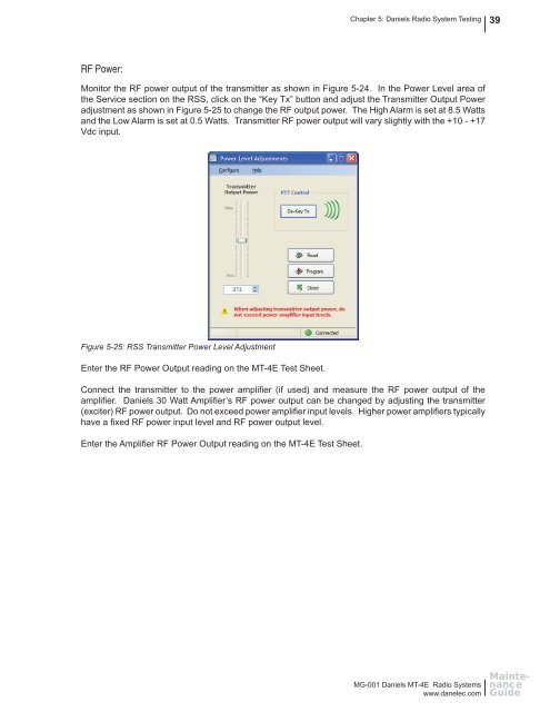
Monitor the RF power output of the transmitter as shown in Figure 5-24. In the Power Level area of<br />
the Service section on the RSS, click on the “Key Tx” button <strong>and</strong> adjust the Transmitter Output Power<br />
adjustment as shown in Figure 5-25 to change the RF output power. The High Alarm is set at 8.5 Watts<br />
<strong>and</strong> the Low Alarm is set at 0.5 Watts. Transmitter RF power output will vary slightly with the +10 - +17<br />
Vdc input.<br />
Figure 5-25: RSS Transmitter Power Level Adjustment<br />
Enter the RF Power Output reading on the <strong>MT</strong>-<strong>4E</strong> Test Sheet.<br />
Connect the transmitter to the power amplifi er (if used) <strong>and</strong> measure the RF power output of the<br />
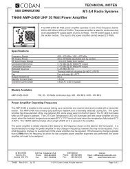
amplifi er. <strong>Daniels</strong> 30 Watt Amplifi er’s RF power output can be changed by adjusting the transmitter<br />
(exciter) RF power output. Do not exceed power amplifi er input levels. Higher power amplifi ers typically<br />
have a fi xed RF power input level <strong>and</strong> RF power output level.<br />
Enter the Amplifi er RF Power Output reading on the <strong>MT</strong>-<strong>4E</strong> Test Sheet.<br />
MG-001 <strong>Daniels</strong> <strong>MT</strong>-<strong>4E</strong> <strong>Radio</strong> <strong>Systems</strong><br />
www.danelec.com<br />
Maintenance<br />
Guide