MT-4E Analog and P25 Digital Radio Systems - Daniels Electronics
MT-4E Analog and P25 Digital Radio Systems - Daniels Electronics
MT-4E Analog and P25 Digital Radio Systems - Daniels Electronics

Create successful ePaper yourself
Turn your PDF publications into a flip-book with our unique Google optimized e-Paper software.
Chapter 5: <strong>Daniels</strong> <strong>Radio</strong> System Testing 41<br />
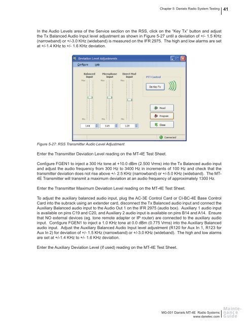
In the Audio Levels area of the Service section on the RSS, click on the “Key Tx” button <strong>and</strong> adjust<br />
the Tx Balanced Audio Input level adjustment as shown in Figure 5-27 until a deviation of +/- 1.5 KHz<br />
(narrowb<strong>and</strong>) or +/-3.0 KHz (wideb<strong>and</strong>) is measured on the IFR 2975. The high <strong>and</strong> low alarms are set<br />
at +/-1.4 KHz to +/- 1.6 KHz deviation.<br />
Figure 5-27: RSS Transmitter Audio Level Adjustment<br />
Enter the Transmitter Deviation Level reading on the <strong>MT</strong>-<strong>4E</strong> Test Sheet.<br />
Confi gure FGEN1 to inject a 300 Hz tone at +10.0 dBm (2.500 Vrms) into the Tx Balanced audio input<br />
<strong>and</strong> adjust the audio frequency from 300 Hz to 3400 Hz in increments of 100 Hz <strong>and</strong> check that the<br />
transmitter deviation does not rise above +/- 2.5 KHz (narrowb<strong>and</strong>) or +/-5.0 KHz (wideb<strong>and</strong>). The <strong>MT</strong>-<br />
<strong>4E</strong> Transmitter will transmit a maximum deviation at an audio frequency of approximately 1300 Hz.<br />
Enter the Transmitter Maximum Deviation Level reading on the <strong>MT</strong>-<strong>4E</strong> Test Sheet.<br />
To adjust the auxiliary balanced audio input, plug the AC-3E Control Card or CI-BC-<strong>4E</strong> Base Control<br />
Card into the subrack using an extender card, disconnect the Tx Balanced audio input <strong>and</strong> connect the<br />
Auxiliary Balanced audio input to the Audio Out 1 on the IFR 2975 (audio box). Auxiliary 1 audio input<br />
is available on pins C19 <strong>and</strong> C20, <strong>and</strong> Auxiliary 2 audio input is available on pins B14 <strong>and</strong> A14. Ensure<br />
that NO external devices (eg. tone remote adapter or IP router) are connected to the auxiliary audio<br />
input. Confi gure FGEN1 to inject a 1.0 KHz tone at 0.0 dBm (0.775 Vrms) into the Auxiliary Balanced<br />
audio input. Adjust the Auxiliary Balanced Audio Input level adjustment (R120 for Aux In 1, R123 for<br />
Aux In 2) for deviation of +/- 1.5 KHz (narrowb<strong>and</strong>) or +/-3.0 KHz (wideb<strong>and</strong>). The high <strong>and</strong> low alarms<br />
are set at +/-1.4 KHz to +/- 1.6 KHz deviation.<br />
Enter the Auxiliary Deviation Level (if used) reading on the <strong>MT</strong>-<strong>4E</strong> Test Sheet.<br />
MG-001 <strong>Daniels</strong> <strong>MT</strong>-<strong>4E</strong> <strong>Radio</strong> <strong>Systems</strong><br />
www.danelec.com<br />
Maintenance<br />
Guide