

WIRE HARNESS INSTALLATION INSTRUCTIONS - Painless Wiring
WIRE HARNESS INSTALLATION INSTRUCTIONS - Painless Wiring
WIRE HARNESS INSTALLATION INSTRUCTIONS - Painless Wiring

You also want an ePaper? Increase the reach of your titles
YUMPU automatically turns print PDFs into web optimized ePapers that Google loves.
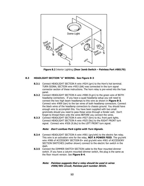
Figure 8.2 Interior Lighting (Door Jamb Switch – <strong>Painless</strong> Part #80170)<br />
8.3 HEADLIGHT SECTION "A" WIRING. See Figure 8-3<br />
8.3.1 Connect HEADLIGHT SECTION A wire #924 (grn) to the Horn's hot terminal.<br />
TURN SIGNAL SECTION wire #953 (blk) was connected in the turn signal<br />
connector section of these instructions. The horn relay is pre-wired into the fuse<br />
panel.<br />
8.3.2 Connect HEADLIGHT SECTION A wire #908 (lt.grn) to the green wire of BOTH<br />
headlamp connectors. If you have a quad headlamp setup you will need to<br />
connect the two high beam headlamps to this wire as shown in Figure 8-3.<br />
Connect wire #909 (tan) to the tan wires of both headlamp connectors. Connect<br />
the black wires of the headlamp connectors to chassis ground. You should have<br />
enough wire to accomplish this. You have been supplied with two small<br />
grommets should you need to pass these wires through a fender well. Don't<br />
forget to thread them onto the wires BEFORE you connect the wires.<br />
8.3.3 Connect HEADLIGHT SECTION A wire #927 (brn) to ALL front park lights.<br />
Connect HEADLIGHT SECTION A wire #925 (blu) to the RIGHT FRONT turn<br />
signal. Connect wire #926 (lt.blu) to the LEFT FRONT turn signal.<br />
Note: Don't confuse Park Lights with Turn Signals.<br />
8.3.4 Connect HEADLIGHT SECTION A wire #901 (gry/wht) to the electric fan relay.<br />
This wire is an activation wire for the relay, NOT A POWER FEED. The gry/wht<br />
wire #906 of ACCESSORY SECTION B+ and gry/wht wire #901 of ACCESSORY<br />
SECTION SWITCHES (neither shown) connect to the electric fan switch in the<br />
dash.<br />
8.3.5 Connect the DIMMER SWITCH SECTION cable to the floor mounted dimmer<br />
switch. If you have a column mounted dimmer switch, the plug is the same as<br />
the floor mount version. See Figure 8-4.<br />
Note: <strong>Painless</strong> suggests that a relay should be used in wires<br />
#906/901 circuit, <strong>Painless</strong> part number 30101.<br />
12


