

WIRE HARNESS INSTALLATION INSTRUCTIONS - Painless Wiring
WIRE HARNESS INSTALLATION INSTRUCTIONS - Painless Wiring
WIRE HARNESS INSTALLATION INSTRUCTIONS - Painless Wiring

Create successful ePaper yourself
Turn your PDF publications into a flip-book with our unique Google optimized e-Paper software.
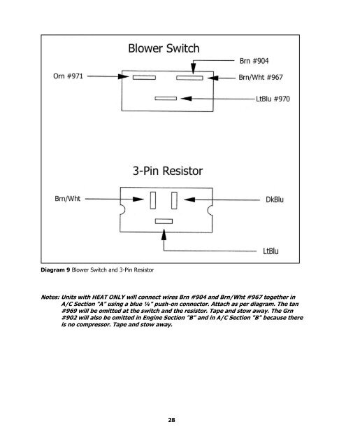
Diagram 9 Blower Switch and 3-Pin Resistor<br />
Notes: Units with HEAT ONLY will connect wires Brn #904 and Brn/Wht #967 together in<br />
A/C Section "A" using a blue ¼" push-on connector. Attach as per diagram. The tan<br />
#969 will be omitted at the switch and the resistor. Tape and stow away. The Grn<br />
#902 will also be omitted in Engine Section "B" and in A/C Section "B" because there<br />
is no compressor. Tape and stow away.<br />
28


