Week 2 Dynamic Characteristics of CANDU Reactors - Nuclear ...
Week 2 Dynamic Characteristics of CANDU Reactors - Nuclear ...
Week 2 Dynamic Characteristics of CANDU Reactors - Nuclear ...

Create successful ePaper yourself
Turn your PDF publications into a flip-book with our unique Google optimized e-Paper software.
<strong>Week</strong> 2 - <strong>Dynamic</strong> <strong>Characteristics</strong> <strong>of</strong> <strong>CANDU</strong> <strong>Reactors</strong> 1-10<br />
<strong>Dynamic</strong> <strong>Characteristics</strong> <strong>of</strong> <strong>CANDU</strong> <strong>Reactors</strong><br />
Prepared by<br />
Dr. Daniel A. Meneley, Senior Advisor, Atomic Energy <strong>of</strong> Canada Ltd. and<br />
Adjunct Pr<strong>of</strong>essor, Department <strong>of</strong> Engineering Physics<br />
McMaster University, Hamilton, Ontario, Canada<br />
Summary:<br />
Refinement <strong>of</strong> concepts important to today’s <strong>CANDU</strong> power plant. Approximations used for<br />
separating those variables important for accident analysis, normal operation, fuel management,<br />
and structural changes. Effects <strong>of</strong> heterogeneity -- Lattice cell effects and neutron cross-section<br />
averaging.<br />
Table <strong>of</strong> Contents<br />
More about this document<br />
<strong>Dynamic</strong> <strong>Characteristics</strong> <strong>of</strong> <strong>CANDU</strong> <strong>Reactors</strong>...............................................................................2<br />
1. Neutron Chain Reaction ......................................................................................................2<br />
2. Operating Domain (safe operating envelope) .....................................................................2<br />
3. Neutron migration area........................................................................................................4<br />
4. Reactor dynamics when the reactor is shut down ...............................................................5<br />
5. Spatial Heterogeneity ..........................................................................................................7<br />
6. Long-term effects ................................................................................................................9<br />
H:\Violeta 1 – Word\web\<strong>Dynamic</strong> <strong>Characteristics</strong> <strong>of</strong> <strong>CANDU</strong> <strong>Reactors</strong>
<strong>Week</strong> 2 - <strong>Dynamic</strong> <strong>Characteristics</strong> <strong>of</strong> <strong>CANDU</strong> <strong>Reactors</strong> 2-10<br />
<strong>Dynamic</strong> <strong>Characteristics</strong> <strong>of</strong> <strong>CANDU</strong> <strong>Reactors</strong><br />
1. Neutron Chain Reaction<br />
Figure 1 depicts the neutron cycle in a thermal reactor. (Fast reactors are somewhat different<br />
because fission occurs mostly at high energies, and neutrons either are absorbed or leak out<br />
before they slow down to<br />
• When Number <strong>of</strong> Slow Neutrons is<br />
Leaked Neutrons<br />
constant, the system is critical.<br />
thermal energy.)<br />
• Fast Neutrons slow down in<br />
In normal operation, a<br />
~ 1 millisecond.<br />
thermal reactor is very near<br />
Delayed Neutrons<br />
to a “critical” state, wherein<br />
from Fission<br />
Prompt<br />
Neutrons<br />
Neutrons<br />
the neutron population is<br />
Diffusing<br />
from<br />
Leaked Neutrons<br />
Fission<br />
independent <strong>of</strong> time (at least<br />
CONTROL THIS TO<br />
"ASHES"<br />
CONTROL HEAT<br />
on the time scale <strong>of</strong> seconds-<br />
(Fission<br />
PRODUCTION<br />
Products)<br />
to-hours.) The population <strong>of</strong><br />
U235<br />
Captured<br />
Fission<br />
Slow Neutrons<br />
Neutrons<br />
neutrons determines the<br />
(Some neutrons are<br />
HEAT<br />
captured in U238 and so<br />
fission rate and, therefore<br />
produce useful fuel - Pu239)<br />
the amount <strong>of</strong> power<br />
Figure 1 – The Neutron Cycle in a Thermal Reactor<br />
produced. To increase<br />
power, we temporarily<br />
reduce the number <strong>of</strong> neutrons captured in control materials – the neutron population increases<br />
exponentially with time. When the desired power level is reached the control materials capture<br />
rate is again increased to keep the total neutron population constant. (Q – approximately, what<br />
reactivity increase is required to change the power level at a rate <strong>of</strong> 0.1 percent per second?).<br />
2. Operating Domain (safe operating envelope)<br />
Automatic control systems are<br />
designed to control the reactor at<br />
constant power within a multi-<br />
Operating Trajectory<br />
parameter domain, as shown in<br />
Figure 2 for a typical <strong>CANDU</strong><br />
power reactor. Assume that the<br />
reactor has been designed to<br />
Design Center<br />
operate under “Design Center”<br />
conditions. During operation<br />
some state variables change and<br />
others are manipulated, causing<br />
Operating Limit<br />
the reactor’s state vector<br />
Trip Limit<br />
(operating trajectory) to “wander<br />
Safety Limit<br />
like a worm” in the n-<br />
dimensional space as time<br />
progresses. (The limitations <strong>of</strong> a<br />
two-dimensional sheet <strong>of</strong> paper are obvious in this Figure.)<br />
• Delayed Neutrons appear after<br />
Neutrons Slowing<br />
~ 10 seconds.<br />
Down<br />
Operating Domain<br />
Operating Margin<br />
Safety Margin<br />
Figure 2 – Safe Operating Domain <strong>of</strong> Control Systems<br />
H:\Violeta 1 – Word\web\<strong>Dynamic</strong> <strong>Characteristics</strong> <strong>of</strong> <strong>CANDU</strong> <strong>Reactors</strong>
<strong>Week</strong> 2 - <strong>Dynamic</strong> <strong>Characteristics</strong> <strong>of</strong> <strong>CANDU</strong> <strong>Reactors</strong> 3-10<br />
The control system always directs the state vector toward Design Center, as shown in Figure 2.<br />
Perturbations such as fuelling, power changes, temperature changes, and so on tend to move the<br />
state vector toward the “Operating Limit”. At this boundary, the normal control system acts<br />
immediately to return the state vector toward Design Center. If, for any reason, (e.g. a large<br />
perturbation) the normal control system cannot do this, the reactor state vector may continue<br />
moving toward the “Trip Limit” at which special safety systems respond automatically. These<br />
systems act quickly, and solely, to reduce reactor power and/or increase heat removal from the<br />
core. They are cocked or “poised” at all times for this purpose.<br />
[Note: Several complex events and decisions led up to the disastrous Chernobyl Unit 4 reactor<br />
accident in April 1986. However, in the end, the accident was initiated by a combination <strong>of</strong> poor<br />
design and poor operation. Poor design <strong>of</strong> safety shutdown rods allowed the operators to reach<br />
an operating state wherein the first movement <strong>of</strong> safety rods (intended, <strong>of</strong> course, to shut down<br />
the reactor) actually led to a reactivity increase and consequent power increase. Poor operation<br />
was indicated by the fact that the operators deliberately put the reactor into an unsafe state prior<br />
to the accident.]<br />
Startup, power level transients, steady-state operation, and shutdown transient states are included<br />
implicitly in the n-dimensional state space represented by the simple diagram in Figure 2. Add<br />
a few more state variables and we can describe subcritical and maintenance states. The concept<br />
is the same - the outer boundary <strong>of</strong> the Operating Domain in the Figure can be compared with<br />
(for example) an aircraft ‘stall’ warning. Protective actions are taken if the aircraft state reaches<br />
the boundary <strong>of</strong> the operating domain (or operating envelope) so as to prevent equipment<br />
damage. There is no comparison between aircraft and a reactor’s automatic safety systems – as<br />
such these would be equivalent to a system that automatically landed the plane in case <strong>of</strong> trouble.<br />
The task equivalent to “landing” is relatively simple in the case <strong>of</strong> a reactor – shut <strong>of</strong>f the chain<br />
reaction, close up the containment, and continue cooling the fuel. Aircraft do not have this<br />
ultimate protective barrier.<br />
Another dimension is added to the operating domain when considerations <strong>of</strong> fuel depletion are<br />
important. Referring to Figure 1, it is clear that action must be taken to maintain a constant<br />
neutron population as the concentration <strong>of</strong> uranium-235 slowly decreases, and as the<br />
concentration <strong>of</strong> neutron-capturing fission products increases. In the short term the reactor<br />
control system acts to keep the state vector (Figure 2) inside the operating envelope. However,<br />
the control system eventually will reach the limit <strong>of</strong> its range and new fuel must be added. In<br />
reactors such as <strong>CANDU</strong> this fuel changing is done daily at full power. This leads to an<br />
operating advantage for this type <strong>of</strong> reactor because the reactor neutronic parameters reach an<br />
approximate equilibrium after a year or so <strong>of</strong> operation and remain constant after that time.<br />
Another advantage <strong>of</strong> this scheme is that it becomes unnecessary to change fuel with the reactor<br />
shut down – when it is more difficult to measure the degree to which the core state is below a<br />
‘critical’ state.<br />
In reactors such as the pressurized water reactor, fuel changing requires reactor shutdown. A<br />
large fraction <strong>of</strong> the fuel is changed at one time and then the reactor is restarted. This major fuel<br />
change requires that a large amount <strong>of</strong> neutron-absorbing material be added to control reactivity.<br />
As a result core properties are changed significantly by refuelling. The Beginning <strong>of</strong> Cycle state<br />
H:\Violeta 1 – Word\web\<strong>Dynamic</strong> <strong>Characteristics</strong> <strong>of</strong> <strong>CANDU</strong> <strong>Reactors</strong>
<strong>Week</strong> 2 - <strong>Dynamic</strong> <strong>Characteristics</strong> <strong>of</strong> <strong>CANDU</strong> <strong>Reactors</strong> 4-10<br />
variables then change slowly over the cycle time <strong>of</strong> approximately one year, finally returning to<br />
End <strong>of</strong> Cycle conditions just prior to the next refueling.<br />
3. Neutron migration area<br />
Reactor size affects the spatial stability <strong>of</strong> power generation in any fission reactor. In general,<br />
large reactors are less stable than are small reactors. (We will see the mathematical expression<br />
<strong>of</strong> this fact later in this course.)<br />
The characteristic size that is most relevant to comparison <strong>of</strong> different reactor types, at a given<br />
power output, is the size expressed in units <strong>of</strong> the mean travel distance (migration length)<br />
between production and absorption in the core. We see from Table 1 that the HWR and the FBR<br />
are much “smaller” in terms <strong>of</strong> neutron diffusion that either the PWR or the BWR. As a result,<br />
these reactors are more stable. In detail, other factors play a part in determining core stability, as<br />
will be examined later.<br />
Table 1: Characteristic Sizes <strong>of</strong> Power <strong>Reactors</strong><br />
Reactor Type Reactor Core Diameter<br />
(cm., typ.)<br />
Neutron Migration<br />
Length (cm., typ.)<br />
Characteristic Size<br />
(migration lengths)<br />
PWR 370. 6.6 56<br />
BWR 470 7.3 64<br />
HWR 700. 20 35<br />
FBR 175. 5 35<br />
The optimum power output <strong>of</strong> a <strong>CANDU</strong> reactor for a given number <strong>of</strong> channels is obtained<br />
when the reactivity <strong>of</strong> approximately half <strong>of</strong> the fuel channels, located in the center <strong>of</strong> the<br />
reactor, is deliberately lowered so that the flux (and therefore the power) is constant across the<br />
so-called ‘inner zone’ <strong>of</strong> the core. This flux flattening results, <strong>of</strong> course, in decreased stability in<br />
this portion <strong>of</strong> the reactor – a small addition <strong>of</strong> reactivity in a flat-flux zone produces a relatively<br />
large flux change. This condition usually is avoided by slightly reducing the reactivity <strong>of</strong> a few<br />
fuel channels near the center <strong>of</strong> the reactor, so as to restore sufficient stability conditions at<br />
minor cost in terms <strong>of</strong> power output.<br />
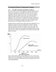
Large thermal reactors are subject to another sort <strong>of</strong> instability, this one induced by production,<br />
capture, and decay <strong>of</strong> the isotope Xenon-135. The best design strategy to eliminate resultant<br />
power fluctuations is to install an automatic control system such as that in the <strong>CANDU</strong>-HWR.<br />
Generally, it is impractical to control these fluctuations manually.<br />
Reflectors are used in all power reactors to reduce neutron losses and to assist in flattening the<br />
power distribution. Escaping neutrons are captured in a uranium radial blanket in the case <strong>of</strong> the<br />
FBR. Production <strong>of</strong> plutonium for new fuel is greatly enhanced by this design feature.<br />
Reflectors are relatively unimportant in the LWR because <strong>of</strong> their very small migration length<br />
and the presence <strong>of</strong> a strongly absorbing steel core barrel surrounding the fuel.<br />
H:\Violeta 1 – Word\web\<strong>Dynamic</strong> <strong>Characteristics</strong> <strong>of</strong> <strong>CANDU</strong> <strong>Reactors</strong>
<strong>Week</strong> 2 - <strong>Dynamic</strong> <strong>Characteristics</strong> <strong>of</strong> <strong>CANDU</strong> <strong>Reactors</strong> 5-10<br />
The <strong>CANDU</strong>-HWR uses a heavy water radial reflector. This reflector also has an important<br />
effect on reactor dynamics because <strong>of</strong> its very long diffusion length.<br />
The mean flight path length <strong>of</strong> a neutron between collisions (the “mean free path”) gives an<br />
indication <strong>of</strong> the degree <strong>of</strong> inhomogeneity <strong>of</strong> any reactor assembly consisting <strong>of</strong> fuel elements<br />
and coolant/moderator. If this flight path is long relative to the thickness/diameter <strong>of</strong> a fuel<br />
element at all neutron energies, the reactor is said to be “quasi-homogeneous’. Most fast reactors<br />
are nearly homogeneous in this sense. The McMaster <strong>Nuclear</strong> Reactor is typical <strong>of</strong> a quasihomogeneous<br />
thermal reactor.<br />
In most thermal power reactors the flight path at some neutron energies is short relative to the<br />
dimension <strong>of</strong> a fuel element, or to the moderator thickness between fuel elements. These<br />
reactors must be treated as “heterogeneous”, with consequent higher complexity in their analysis.<br />
The LWR and the HWR are typical heterogeneous reactors. Heterogeneity can be seen at more<br />
than one level; for example, mechanical control absorbers in a <strong>CANDU</strong> exhibit a second level <strong>of</strong><br />
heterogeneity that must also be considered in analysis. These effects will be discussed in later<br />
chapters where specific cases arise that are important to reactor dynamic behaviour.<br />
4. Reactor dynamics when the reactor is shut down<br />
Many <strong>of</strong> the available theoretical treatments <strong>of</strong> reactor dynamics do not address the important<br />
field <strong>of</strong> the shut down or “subcritical” states <strong>of</strong> the reactor. This observation should be<br />
considered along with the historical observation that the majority <strong>of</strong> reactor accidents actually<br />
began from a shutdown state. One could postulate several reasons for this common omission,<br />
and the omission itself should not be blamed for all such accidents. However, if the lack <strong>of</strong><br />
knowledge <strong>of</strong> fission reactors in their subcritical state might have been responsible even partly<br />
for one such accident, we are fully justified in studying this case.<br />
As written, the simple neutron kinetics program referred to in the <strong>Week</strong> 1 course notes does not<br />
consider the subcritical condition. In order to do so we must add another term to the equation<br />
solved therein. The following equation set defines the point-reactor kinetic behaviour in a<br />
reactor containing an external neutron source. This equation will be derived later in this course –<br />
however, it is expected that the student already is familiar with the general form:<br />
dN t S tC%<br />
k0<br />
1<br />
¯<br />
N t<br />
sCs<br />
t S t<br />
dt <br />
t k0<br />
t<br />
œ<br />
% %<br />
¡ ¢<br />
l l ° ±<br />
s<br />
dC% s<br />
t<br />
C%<br />
dt l t<br />
<br />
%<br />
M <br />
M 1, 6<br />
s<br />
N t <br />
sCs<br />
t s <br />
1<br />
S G Z<br />
Dt<br />
<br />
<br />
*<br />
t F t M t t<br />
- Reactivity<br />
H:\Violeta 1 – Word\web\<strong>Dynamic</strong> <strong>Characteristics</strong> <strong>of</strong> <strong>CANDU</strong> <strong>Reactors</strong>
<strong>Week</strong> 2 - <strong>Dynamic</strong> <strong>Characteristics</strong> <strong>of</strong> <strong>CANDU</strong> <strong>Reactors</strong> 6-10<br />
1<br />
C%<br />
G C Z<br />
Dt<br />
<br />
<br />
*<br />
s<br />
F t t<br />
s<br />
- Effective Delayed Neutron Fraction<br />
F(t) and M(t) are, respectively, the space-and-time dependent fission neutron source and sink.<br />
D(t) is the weighted integral <strong>of</strong> the fission neutron source (inner product).<br />
œ C % s<br />
C<br />
%<br />
s<br />
l<br />
<br />
1<br />
Dt<br />
*<br />
t G v Z t<br />
<br />
<br />
s 1,6 - Delayed Neutron Fraction<br />
<br />
1/ - Prompt Neutron Lifetime<br />
%<br />
<br />
1<br />
Dt<br />
*<br />
Cs<br />
t G Cs<br />
t<br />
l t<br />
<br />
- Effective Neutron Precursor Concentration<br />
S%<br />
t<br />
<br />
1<br />
<br />
Dt<br />
l t<br />
G<br />
*<br />
S t<br />
<br />
- Effective Source Strength<br />
The non-physical parameter k 0 is the inverse <strong>of</strong> the largest eigenvalue <strong>of</strong> the source-free reactor<br />
equation, for the known subcritical steady state.<br />
At steady-state initial conditions, the left hand side <strong>of</strong> each <strong>of</strong> the seven governing equations is<br />
zero and by definition, N(0) = 1.0, and ρ(0) = 0. Therefore,<br />
C%<br />
N<br />
s<br />
1 C%<br />
0 1,6<br />
Ms<br />
l<br />
l S 0<br />
01.0<br />
<br />
%<br />
k0<br />
1¬<br />
ž k<br />
žŸ ®<br />
s<br />
<br />
s <br />
0<br />
and<br />
Existence <strong>of</strong> a steady-state solution requires that k 0 < 1.0; that is, the reactor must be subcritical.<br />
As the reactor approaches a critical condition via any given state trajectory (for example by<br />
increasing fuel concentration or by reducing the neutron leakage) k 0 tends toward unity and N(0)<br />
increases. But if the initial source is identically zero, there will be no neutrons present and so<br />
N(0) = 0.0 even if k 0 >1.0. This (hypothetical) situation obviously is very dangerous because<br />
addition <strong>of</strong> only one neutron to the system may lead to a very rapid energy release. Such events<br />
in real systems (for example the recent ‘flash criticality’ accident in the fuel processing facility at<br />
Tokai in Japan and the fuel loading incident in the McMaster <strong>Nuclear</strong> Reactor) usually result<br />
from mistaken physical changes that alter the reactor state from k 0 less that unity to k 0 greater<br />
than unity.<br />
It is obvious that one necessary condition for safety in a subcritical reactor is that an external<br />
neutron source be present at all times. Its strength requirement is determined by the resultant<br />
H:\Violeta 1 – Word\web\<strong>Dynamic</strong> <strong>Characteristics</strong> <strong>of</strong> <strong>CANDU</strong> <strong>Reactors</strong>
<strong>Week</strong> 2 - <strong>Dynamic</strong> <strong>Characteristics</strong> <strong>of</strong> <strong>CANDU</strong> <strong>Reactors</strong> 7-10<br />
neutron flux level and the sensitivity <strong>of</strong> neutron detectors – these detectors also are essential so<br />
that any change in the state <strong>of</strong> subcriticality can be detected by the operating staff and so that<br />
automatic safety systems will have time to respond. The second part <strong>of</strong> this safety requirement<br />
is, <strong>of</strong> course, that sudden physical changes that lead to an increase in k 0 be limited in rate or in<br />
absolute magnitude.<br />
The ‘approach to critical’ (or otherwise, the methods for safely starting up a reactor) will be<br />
addressed later in this course.<br />
Referring back to Figure 1, it is obvious that the presence <strong>of</strong> an external source <strong>of</strong> neutrons<br />
means that an operating reactor will never be precisely critical. It must be kept in a state slightly<br />
below critical so as to maintain constant power. However, this aspect <strong>of</strong> operation becomes<br />
important mainly under shutdown conditions. Here again, the HWR is unique in that the<br />
gamma-neutron reaction in deuterium produces a significant neutron source under all conditions<br />
except the first startup with all-fresh fuel. Spontaneous fission <strong>of</strong> some actinide elements also<br />
produces neutrons, but in small numbers. In all cases in which there is no other large source <strong>of</strong><br />
neutrons, a special neutron-emitting source must be added to the reactor during startup.<br />
Consideration <strong>of</strong> reactor dynamics under shutdown conditions also must include the dynamics <strong>of</strong><br />
high-absorption fission products, especially the Iodine-Xenon chain. Following shutdown from<br />
high power, the Xenon concentration increases so that a thermal reactor generally cannot be<br />
restarted. The eventual decay <strong>of</strong> the Xenon-135 isotope permits restart after 30-40 hours’ delay.<br />
Restarting a thermal reactor containing substantial amounts <strong>of</strong> Xenon-135 requires careful<br />
manipulation <strong>of</strong> in-reactor control systems, because the initial power increase ‘burns up’ this<br />
residual Xenon and increases the reactivity <strong>of</strong> the core.<br />
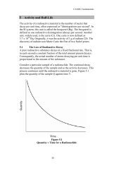
Another important special situation arises after reactor shutdown from high power. Fission<br />
products produce about 7 percent <strong>of</strong> the total heat during operation; after the chain reaction is<br />
shut <strong>of</strong>f, this heat is still produced. The amount decays to about 1 percent <strong>of</strong> initial power after 3<br />
hours, and continues to decrease thereafter. Nevertheless, removal <strong>of</strong> this ‘decay heat’ is an<br />
important consideration in fuel cooling. [Note: During the 1979 accident at Three Mile Island,<br />
the fuel was well cooled for about 2 hours following reactor shutdown. Mistakes in operation<br />
then led to removal <strong>of</strong> cooling from some fuel after that time; the fuel that was uncooled then<br />
melted (at ~2800 C) and posed a significant risk to the integrity <strong>of</strong> the pressure vessel.<br />
Fortunately, this molten fuel was re-solidified without extensive heat transfer to the vessel wall.]<br />
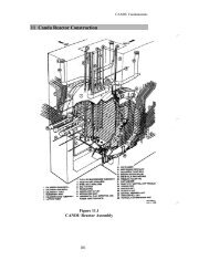
5. Spatial Heterogeneity<br />
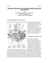
Figures 1 to 4 <strong>of</strong> the general description given in [Link-reference to Lecture 5 <strong>of</strong> “6-Lecture<br />
Course”] show the geometry <strong>of</strong> the <strong>CANDU</strong>-6 reactor. Those Figures can be “zoomed” to view<br />
details <strong>of</strong> the reactor core design. The most notable features for our purposes are (a) the<br />
horizontal (z-direction) orientation <strong>of</strong> fuel channels, the (b) vertical (y-direction) orientation <strong>of</strong><br />
some control devices, and the (c) horizontal (x-direction) orientation <strong>of</strong> other control devices.<br />
The fuel channels are filled with fuel plus heavy water; the control assemblies are either filled<br />
with neutron-absorbing material or heavy water. The absorbing and neutron producing<br />
properties <strong>of</strong> the fuel change as the fuel is irradiated. Spaces between these structures are filled<br />
with pure heavy water moderator.<br />
H:\Violeta 1 – Word\web\<strong>Dynamic</strong> <strong>Characteristics</strong> <strong>of</strong> <strong>CANDU</strong> <strong>Reactors</strong>
<strong>Week</strong> 2 - <strong>Dynamic</strong> <strong>Characteristics</strong> <strong>of</strong> <strong>CANDU</strong> <strong>Reactors</strong> 8-10<br />
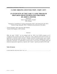
It is obvious that the modeling <strong>of</strong><br />
neutron migration in this complex<br />
lattice depends not only on the<br />
properties <strong>of</strong> the isotopes, but also on<br />
their location in the lattice as well as on<br />
the proximity <strong>of</strong> other isotopes in other<br />
parts <strong>of</strong> the lattice. This extremely<br />
heterogeneous geometry is simplified<br />
to some extent by the fact that most <strong>of</strong><br />
the neutrons present are well<br />
thermalized. A typical neutron flux<br />
distribution in a <strong>CANDU</strong> lattice is<br />
shown in Figure 3. As can be seen,<br />
most <strong>of</strong> the fast neutrons produced in<br />
the fuel diffuse to the moderator region<br />
where they are slowed down to thermal<br />
energies, and then diffuse back to the<br />
fuel where they are absorbed.<br />
Relative Neutron Flux<br />
Properties <strong>of</strong> the core materials are<br />
Figure 3 – Typical Flux Distribution in <strong>CANDU</strong> Lattice Cell<br />
normally averaged over discrete<br />
volumes and over discrete energy intervals and collected in tabular form suitable for<br />
interpolation over space and fuel irradiation so as to select appropriate values to represent the<br />
specific state <strong>of</strong> the core (fuel irradiation, temperature, near-neighbor effects) at any location.<br />
The time-dependence <strong>of</strong> these properties (due to changes in density, temperature, etc.) also is<br />
pre-calculated and stored in interpolation tables for use in dynamic analysis.<br />
Most reactors must shut down for refueling. In these systems, extensive computer simulations<br />
are done to select the optimum new-fuel loading (enrichment, burnable poison concentrations,<br />
spatial core layout, excess reactivity requirements, etc.) for the next ‘cycle’ <strong>of</strong> about one year<br />
duration. Once the final calculation is made fuel is ordered and the decisions become very<br />
difficult to reverse. The <strong>CANDU</strong> system is fuelled at full power, at a rate <strong>of</strong> 15-20 identical fuel<br />
bundles per day (2-3 fuel channels). Pre-calculation is necessary to select the best channels for<br />
refueling, to maintain the correct local power distribution, core reactivity, etc. Neither<br />
enrichment nor burnable poison is required. The shift supervisor makes the final choice <strong>of</strong><br />
channels to be fuelled and the fuelling system operator initiates the automatic fuelling system.<br />
Addition <strong>of</strong> new fuel in <strong>CANDU</strong> initiates a small reactor transient because the new-fuel<br />
reactivity is higher than that <strong>of</strong> old fuel. The zone controllers compensate this reactivity addition<br />
automatically, to maintain reactor power and correct local power levels. Removal <strong>of</strong> any failed<br />
fuel elements is essentially identical to refueling. New bundles are added to replace those<br />
containing failed elements.<br />
3.<br />
2.<br />
1.<br />
0.<br />
Fuel<br />
Bundle<br />
Thermal Flux<br />
Lattice<br />
Cell<br />
Fast Flux<br />
5. 16.<br />
Equivalent Radius (cm.)<br />
H:\Violeta 1 – Word\web\<strong>Dynamic</strong> <strong>Characteristics</strong> <strong>of</strong> <strong>CANDU</strong> <strong>Reactors</strong>
<strong>Week</strong> 2 - <strong>Dynamic</strong> <strong>Characteristics</strong> <strong>of</strong> <strong>CANDU</strong> <strong>Reactors</strong> 9-10<br />
6. Long-term effects<br />
Power reactors must be designed to operate for 30 years or more. During such long periods, the<br />
high-intensity neutron and gamma irradiation leads to degradation <strong>of</strong> materials. Examples are:<br />
radiolysis <strong>of</strong> water, transport <strong>of</strong> active corrosion products to inhabited areas, swelling and<br />
embrittlement <strong>of</strong> steel, production and transport <strong>of</strong> tritiated water, and creep <strong>of</strong> zirconium<br />
pressure tubes. Such processes are an intrinsic part <strong>of</strong> the “dynamics” <strong>of</strong> any power reactor’s<br />
operation even though their characteristic time scale is quite long, because the operating life <strong>of</strong> a<br />
power reactor may itself extend for 60 years or more.<br />
H:\Violeta 1 – Word\web\<strong>Dynamic</strong> <strong>Characteristics</strong> <strong>of</strong> <strong>CANDU</strong> <strong>Reactors</strong>
<strong>Week</strong> 2 - <strong>Dynamic</strong> <strong>Characteristics</strong> <strong>of</strong> <strong>CANDU</strong> <strong>Reactors</strong> 10-10<br />
About this document<br />
Back to page 1<br />
Author and affiliation: Daniel A. Meneley, Adjunct Pr<strong>of</strong>essor, Department <strong>of</strong> Engineering<br />
Physics, McMaster University, Hamilton, Ontarion, Canada; Senior Advisor, Marketing and<br />
Sales, Atomic Energy <strong>of</strong> Canada ltd., Mississauga, Ontario, Canada<br />
Revision History:<br />
- Revision 0, Febryary 12, 2001, initial creation<br />
- Source document archive location: h:\Violeta 1 – Word\web\<strong>Dynamic</strong><br />
<strong>Characteristics</strong> <strong>of</strong> <strong>CANDU</strong> <strong>Reactors</strong>.doc<br />
- Contact person: Violeta Sibana<br />
H:\Violeta 1 – Word\web\<strong>Dynamic</strong> <strong>Characteristics</strong> <strong>of</strong> <strong>CANDU</strong> <strong>Reactors</strong>