2010-064 - (SUP 10-01) - Town of Morrisville
2010-064 - (SUP 10-01) - Town of Morrisville
2010-064 - (SUP 10-01) - Town of Morrisville

Create successful ePaper yourself
Turn your PDF publications into a flip-book with our unique Google optimized e-Paper software.
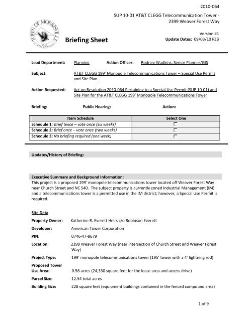
<strong>20<strong>10</strong></strong>-<strong>064</strong><br />
<strong>SUP</strong> <strong>10</strong>-<strong>01</strong> AT&T CLEGG Telecommunication Tower -<br />
2399 Weaver Forest Way<br />
Briefing Sheet<br />
Version #1<br />
Update Dates: 09/03/<strong>10</strong> PZB<br />
Lead Department: Planning Action Officer: Rodney Wadkins, Senior Planner/GIS<br />
Subject:<br />
Action Requested:<br />
AT&T CLEGG 199’ Monopole Telecommunications Tower – Special Use Permit<br />
and Site Plan<br />
Act on Resolution <strong>20<strong>10</strong></strong>-<strong>064</strong> Pertaining to a Special Use Permit (<strong>SUP</strong> <strong>10</strong>-<strong>01</strong>) and<br />
Site Plan for the AT&T CLEGG 199’ Monopole Telecommunications Tower<br />
Briefing: Public Hearing: Action:<br />
Item Schedule<br />
Schedule 1: Brief twice – vote once (six weeks)<br />
Schedule 2: Brief once – vote once (two weeks)<br />
Schedule 3: No briefing required (one week)<br />
Select One<br />
Updates/History <strong>of</strong> Briefing:<br />
Executive Summary and Background Information:<br />
This project is a proposed 199’ monopole telecommunications tower located <strong>of</strong>f Weaver Forest Way<br />
near Church Street and NC 540. The subject property is currently zoned Industrial Management (IM)<br />
and a telecommunications tower is a permitted use in the IM district; however, a Special Use Permit is<br />
required.<br />
Site Data<br />
Property Owner:<br />
Developer:<br />
PIN: 0746-47-8679<br />
Location:<br />
Project Type:<br />
Proposed Tower<br />
Use Area:<br />
Parcel Size:<br />
Building Size:<br />
Katherine R. Everett Heirs c/o Robinson Everett<br />
American Tower Corporation<br />
2399 Weaver Forest Way (near intersection <strong>of</strong> Church Street and Weaver Forest<br />
Way)<br />
199’ monopole telecommunications tower (195’ tower with a 4’ lightning rod)<br />
0.56 acres (24,330 square feet for the lease area and access drive)<br />
12.54 total acres<br />
228 square feet (equipment buildings contained in the fenced compound area)<br />
1 <strong>of</strong> 9
Parking:<br />
Impervious Surface: 4.09%<br />
Setbacks:<br />
1 space required/2 spaces provided<br />
Front: 200 feet<br />
North Side: <strong>10</strong>0 feet<br />
South Side: 200 feet<br />
Rear: 200 feet<br />
<strong>20<strong>10</strong></strong>-<strong>064</strong><br />
<strong>SUP</strong> <strong>10</strong>-<strong>01</strong> AT&T CLEGG Telecommunication Tower -<br />
2399 Weaver Forest Way<br />
Maximum Height: 200 feet (per the <strong>Morrisville</strong> Zoning Ordinance)<br />
Zoning:<br />
Industrial Management (IM)<br />
Surrounding Zoning/ Uses:<br />
North: Industrial Management (NC540) and Residential Multifamily-CU (Everett Crossing)<br />
South: Residential-8 (Providence Place)<br />
East: Residential-8 (Providence Place)<br />
West: Agriculture District (AD) – Vacant and Progress Energy power line easement<br />
FEMA Floodplain: Property is not located within a <strong>10</strong>0 year FEMA floodplain.<br />
Stream Buffers: Property is located within the Cape Fear River Basin and there are fifty-foot (50’)<br />
stream buffers.<br />
Site Plan Features<br />
Site Access<br />
The developer is proposing access to the site via one entrance along Weaver Forest Way.<br />
Sidewalks<br />
No additional sidewalk is proposed. Sidewalk currently exists along Weaver Forest Way.<br />
Lighting<br />
No lighting is proposed on the 199’ monopole telecommunications tower. A small motion-detector<br />
light will be installed in the compound area for technicians if repairs at night are necessary.<br />
RDU Airport Noise Contour<br />
The proposed 199’ monopole telecommunications tower falls within the Airport Noise contours;<br />
however, since none <strong>of</strong> the equipment buildings are habitable, soundpro<strong>of</strong>ing is not required.<br />
Additionally, because <strong>of</strong> the height <strong>of</strong> the 199’ monopole telecommunications tower and the fact that<br />
it falls within airport flight paths, approval from the Federal Aviation Administration (FAA), was<br />
required (see EXHIBIT 8).<br />
Transportation Improvements<br />
No transportation improvements are proposed nor are they required.<br />
Greenway<br />
Per a requirement <strong>of</strong> the Special Use Permit the developer will be responsible for constructing a<br />
2 <strong>of</strong> 9
<strong>20<strong>10</strong></strong>-<strong>064</strong><br />
<strong>SUP</strong> <strong>10</strong>-<strong>01</strong> AT&T CLEGG Telecommunication Tower -<br />
2399 Weaver Forest Way<br />
portion <strong>of</strong> a <strong>10</strong>-foot asphalt greenway within a 30-foot public easement (see Site Plan Sheet C-1),<br />
which will located within the <strong>10</strong>0-foot landscape buffer adjacent to NC 540 to the north and within the<br />
Progress Energy power line easement to the west.<br />
The proposed greenway will stop short <strong>of</strong> the stream (near the southwest corner <strong>of</strong> the property) so<br />
the <strong>Town</strong> can make an easier transition into it with the construction <strong>of</strong> the Providence Place greenway<br />
segment coming up from the south.<br />
Landscaping and Buffering<br />
The proposed landscape buffers, street yard, and fenced compound area foundation plantings meet<br />
the minimum standards <strong>of</strong> the Zoning Ordinance.<br />
The Planning Department determined that allowing the greenway within the <strong>10</strong>0-foot landscape buffer<br />
was in the public interest because by doing so provided better separation between the proposed<br />
greenway and telecommunications tower fenced compound area and the access drive. Additionally,<br />
the greenway will meander through the existing wooded area to minimize the removal <strong>of</strong> existing<br />
vegetation.<br />
Special Use Permit (<strong>SUP</strong>) Process<br />
Per Part C, Article IV: Table <strong>of</strong> Permitted Uses <strong>of</strong> the Zoning Ordinance, a telecommunications tower<br />
located in the Industrial Management (IM) Zoning District requires approval <strong>of</strong> a Special Use Permit<br />
(<strong>SUP</strong>) from the <strong>Morrisville</strong> <strong>Town</strong> Council.<br />
The applicant is required to submit a site plan, a written description <strong>of</strong> the project and evidence to<br />
support the findings <strong>of</strong> a <strong>SUP</strong>.<br />
A public comment session shall be held by the Planning and Zoning Board and a public hearing shall be<br />
held by the <strong>Town</strong> Council.<br />
Per the Zoning Ordinance, the Planning and Zoning Board shall review the <strong>SUP</strong>, site plan and supporting<br />
documents, and forward a recommendation <strong>of</strong> approval, approval with conditions, or denial to the<br />
<strong>Town</strong> Council. The Planning and Zoning Board’s recommendation “shall be based on compliance with<br />
specific standards <strong>of</strong> this ordinance and conditions applicable to the proposed special use.”<br />
The following six (6) general findings, based on evidence and testimony received at a public hearing,<br />
must be made in order for the <strong>Town</strong> Council to approve any <strong>SUP</strong> (Part C, Article VII, Section 1 <strong>of</strong> the<br />
Zoning Ordinance). The evidence submitted by the applicant in support <strong>of</strong> these findings is provided<br />
in EXHIBIT A.<br />
a) That the proposed development or use will not materially endanger the public health or<br />
safety;<br />
Staff response: Based on the information provided by the applicant, the development or use as<br />
proposed will not materially endanger the public health or safety. The proposed development<br />
will adhere to applicable local, state, and federal regulatory requirements, as well as comply<br />
with the <strong>Town</strong> <strong>of</strong> <strong>Morrisville</strong> Zoning Ordinance.<br />
b) That the proposed development or use will not substantially injure the value <strong>of</strong> adjoining<br />
property;<br />
Staff response: Based on the information provided in the property impact report prepared by<br />
3 <strong>of</strong> 9
<strong>20<strong>10</strong></strong>-<strong>064</strong><br />
<strong>SUP</strong> <strong>10</strong>-<strong>01</strong> AT&T CLEGG Telecommunication Tower -<br />
2399 Weaver Forest Way<br />
Craig D. Smith, MAI, the development will not have an adverse impact on adjoining property<br />
values.<br />
c) That the proposed development or use will be in harmony with the scale, bulk, coverage,<br />
density, and character <strong>of</strong> the neighborhood in which it is located;<br />
Staff response: Based on the information provided by the applicant, and due to the fact that<br />
NC-540 is located immediately to the north and a 265 foot wide Progress Energy Transmission<br />
line is located immediately to the west, the development as proposed is in harmony with the<br />
scale, bulk, coverage, density, and character <strong>of</strong> the neighborhood in which it is located.<br />
d) That the proposed development or use will generally conform with the Comprehensive plan<br />
and other <strong>of</strong>ficial plans adopted by the <strong>Town</strong>;<br />
Staff response: Because the applicant will be constructing a greenway, the development as<br />
proposed will generally conform to the Comprehensive plan and other <strong>of</strong>ficial plans adopted by<br />
the <strong>Town</strong>.<br />
e) That the proposed development or use is appropriately located with respect to<br />
transportation facilities, water and sewer supply, fire and police protection, and similar<br />
facilities; and<br />
Staff response: Based on the information provided by the applicant, the development or use as<br />
proposed is appropriately located with respect to transportation facilities, water and sewer<br />
supply, fire and police protection, and similar facilities.<br />
f) That the proposed development or use will not cause undue traffic congestion or create a<br />
traffic hazard.<br />
Staff response: Based on the information provided by the applicant for other similar tower<br />
sites, the use as proposed will not cause undue traffic congestion or create a traffic hazard.<br />
Furthermore, twenty (20) additional findings for certain special uses, based on evidence and testimony<br />
received at a public hearing, must be made in order for the <strong>Town</strong> Council to approve the <strong>SUP</strong><br />
specifically for a telecommunications tower (Part C, Article VII, Section 2.<strong>10</strong> <strong>of</strong> the Zoning Ordinance).<br />
The evidence submitted by the applicant in support <strong>of</strong> these additional findings is provided in<br />
EXHIBIT B.<br />
Finally, per the Zoning Ordinance, if <strong>Town</strong> Council approves the <strong>SUP</strong>, the use shall be exercised or<br />
consummated within a time limit set by the <strong>Town</strong> Council or within one (1) year if no such time limit is<br />
established. Otherwise, the permit shall be null and void. “Exercised and consummated” shall mean<br />
that binding contracts have been set for the construction <strong>of</strong> the principal structures; or in the absence<br />
<strong>of</strong> contracts that the principal structure is under construction to a substantial degree; or the<br />
prerequisite conditions involving substantial investment are contracted for, in substantial<br />
development, or completed.<br />
Staff Recommendation:<br />
In staff’s opinion, the applicant has provided sufficient documentation to satisfy the required findings<br />
for the Special Use Permit.<br />
Therefore, the Planning Department recommends approval <strong>of</strong> the Special Use Permit and Site Plan<br />
(signed and seal date <strong>of</strong> August 18, <strong>20<strong>10</strong></strong>) for the AT&T CLEGG 199’ Monopole Telecommunications<br />
4 <strong>of</strong> 9
<strong>20<strong>10</strong></strong>-<strong>064</strong><br />
<strong>SUP</strong> <strong>10</strong>-<strong>01</strong> AT&T CLEGG Telecommunication Tower -<br />
2399 Weaver Forest Way<br />
Tower to be located at 2399 Weaver Forest Way subject to the following condition:<br />
1. Prior to the acceptance <strong>of</strong> the maintenance <strong>of</strong> the <strong>10</strong>-foot greenway, the property owner shall<br />
dedicate a 30-foot wide public greenway easement containing the <strong>10</strong>-foot greenway.<br />
Attachments:<br />
• RES <strong>20<strong>10</strong></strong>-<strong>064</strong> for <strong>SUP</strong><strong>10</strong>-<strong>01</strong> AT&T CLEGG Telecommunications Tower<br />
• <strong>SUP</strong><strong>10</strong>-<strong>01</strong> document to be recorded<br />
• EXHIBIT A – Article VII – <strong>SUP</strong> Findings from applicant – Supporting Evidence<br />
• EXHIBIT B - Article VII – Additional <strong>SUP</strong> Findings from applicant – Supporting Evidence<br />
• EXHIBIT 1A – Map <strong>of</strong> existing towers within 2 mile radius<br />
• EXHIBIT 2 – Collocation Certificate<br />
• EXHIBIT 3 – Tax map with 500 foot buffer<br />
• EXHIBIT 4 – RF Justification letter<br />
• EXHIBIT 5 – RF Emissions Certification<br />
• EXHIBIT 6 – Photo Simulations <strong>of</strong> tower height<br />
• EXHIBIT 7 – Cover Letter and Surrounding property owner notification labels<br />
• EXHIBIT 8 – FAA approval letter<br />
• EXHIBIT 9 – NC Historic Preservation Office clearance form<br />
• EXHIBIT <strong>10</strong> – Tower Design – stamped PDF ATC CLEGG<br />
• EXHIBIT 12 – Property Impact Report CLEGG TOWER – 6-7-<strong>10</strong><br />
• EXHIBIT 14 – CLEGG Stormwater Impact Analysis – 6-3-<strong>10</strong><br />
• EXHIBIT 15 – ToM completed site plan check list<br />
• EXHIBIT 16 – Letter from applicant to surrounding property owners<br />
• EXHIBIT 17 – Foundation Design – Stamped PDF<br />
• EXHIBIT 18 – Site Plan and CD Set PDF - AT&T CLEGG Telecommunications Tower<br />
• EXHIBIT 19 – Public Notice letter from Planning Department to surrounding property owners<br />
• EXHIBIT 20 – Aerial and Zoning map<br />
Advisory Board/Committee Review:<br />
Planning and Zoning Board – September 9, <strong>20<strong>10</strong></strong><br />
Board/Committee Recommendation:<br />
Advisory Board/Committee Meeting Date and Minutes:<br />
September 9, <strong>20<strong>10</strong></strong>:<br />
Meeting Goals and Initiatives Adopted by the Council:<br />
(Select by checking the box for all Initiatives that are met by this briefing sheet’s proposal. Area for<br />
5 <strong>of</strong> 9
additional comments under table. )<br />
Goals<br />
1. A mix <strong>of</strong> land uses that is<br />
environmentally sensitive<br />
and sustains livability in a<br />
changing community<br />
2. A strong and stable financial<br />
position that fully utilizes all<br />
resources in a responsible,<br />
efficient and effective<br />
manner<br />
3. Community services that<br />
sustain or enhance the<br />
quality <strong>of</strong> life<br />
4. Plan transportation and other<br />
public infrastructure to<br />
address community needs<br />
5. A town image with a strong,<br />
positive identity valued by<br />
residents, businesses and<br />
<strong>20<strong>10</strong></strong>-<strong>064</strong><br />
<strong>SUP</strong> <strong>10</strong>-<strong>01</strong> AT&T CLEGG Telecommunication Tower -<br />
2399 Weaver Forest Way<br />
Initiatives<br />
1.1 Implement Updated Land Use Plan<br />
1.2 Continue Implementation <strong>of</strong> adopted <strong>Town</strong> Center Plan<br />
1.3 Maintain a formal acquisition and implementation strategy<br />
for parks, greenways, and open space<br />
1.4 Evaluate ordinances and policies that contribute to a<br />
sustainable and well planned community.<br />
2.1. Maintain a strategic financial plan<br />
2.2. Ensure proper use <strong>of</strong> resources by enhancing internal<br />
controls<br />
2.3. Identify potential new funding opportunities for specific<br />
town projects and services<br />
2.4. Continue developing town infrastructure evaluation<br />
programs to analyze costs, prioritize maintenance, and<br />
secure funding<br />
3.1. Provide a safe community<br />
3.2. Continually evaluate emergency response needs and<br />
capabilities<br />
3.3. Provide and promote healthy community activities and<br />
programs<br />
3.4. Provide accessible and safe public parks, recreational<br />
programs, cultural resources and facilities<br />
3.5. Continue developing and implementing strategies to<br />
enhance customer service<br />
3.6. Refine and implement a performance measurement process<br />
to provide better information for budgetary decision-making<br />
and create a stronger link between allocation <strong>of</strong> resources<br />
and desired results.<br />
3.7. Continually review and identify internal processes and<br />
community services to improve their efficiency and<br />
effectiveness<br />
4.1. Implement and maintain updated Transportation Plan<br />
4.2. Continue developing a reimbursement policy, developer<br />
requirements and regional partnerships for transportation<br />
and public infrastructure<br />
4.3. Develop and implement a Stormwater Management Plan,<br />
including creating a self-sustaining funding mechanism<br />
4.4. Identify critical areas <strong>of</strong> traffic congestion and appropriate<br />
strategies to resolve transportation problems, drawing on<br />
NCDOT and regional partners.<br />
4.5. Continue developing a capital fund strategy for<br />
infrastructure needs, including the <strong>Town</strong> Center<br />
4.6. Continue evaluating the costs and benefits <strong>of</strong> in-house vs.<br />
contract engineering services<br />
4.7. Work to promote installation <strong>of</strong> infrastructure in a timely<br />
manner to support private development<br />
5.1. Develop and maintain liaison with other elected <strong>of</strong>ficials,<br />
agencies, jurisdictions, and stakeholders<br />
5.2. Promote transparency in town government programs and<br />
6 <strong>of</strong> 9
visitors<br />
6. Regional partnerships to<br />
grow and develop new<br />
resources and opportunities<br />
7. Environmentally responsible<br />
and energy efficient<br />
community<br />
8. A healthy and rewarding<br />
work culture where<br />
employees are our primary<br />
asset in delivering high<br />
quality services to the<br />
community<br />
<strong>20<strong>10</strong></strong>-<strong>064</strong><br />
<strong>SUP</strong> <strong>10</strong>-<strong>01</strong> AT&T CLEGG Telecommunication Tower -<br />
2399 Weaver Forest Way<br />
processes<br />
5.3 Promote high quality development and attractive<br />
community appearance<br />
5.4 Continue to require pr<strong>of</strong>essionalism and friendliness <strong>of</strong> staff<br />
5.5 Cultivate a responsive environment encouraging community<br />
comments and feedback.<br />
6.1. Develop and maintain liaison with other elected <strong>of</strong>ficials,<br />
agencies, jurisdictions, and stakeholders<br />
6.2. Provide educational training for Committee/Board members<br />
and Council members<br />
6.3. Continue active participation in forums for regional<br />
cooperation<br />
7.1. Evaluate and implement changes to town operations<br />
7.2. Evaluate and implement changes to <strong>Town</strong> Ordinances, plans<br />
and policies<br />
8.1. Recruit and retain competent committed staff<br />
8.2. Create a healthy work environment that promotes high<br />
morale<br />
8.3. Foster career development and growth opportunities<br />
8.4. Encourage employees to identify opportunities to improve<br />
efficiencies and effectiveness<br />
9. Citizen Involved government 9.1. Encourage citizens to volunteer within the community<br />
9.2. Diversify the methods <strong>of</strong> communicating with citizens to<br />
provide information on town news and issues<br />
9.3. Increase contact with the business community about town<br />
news and issues<br />
9.4. Develop and advance opportunities for partnership with<br />
local schools and non-pr<strong>of</strong>it groups<br />
9.5. Increase public involvement in town government programs<br />
and processes<br />
Goals and Initiatives Additional Comments:<br />
NONE<br />
Resource Impact:<br />
Staff time required if item is approved:<br />
Other Potential Impacts:<br />
NONE APPLICABLE<br />
No Additional<br />
Staff Coordination:<br />
Check the box for those required to comment on left. To comment-click in the box and select.<br />
(2 nd Briefing is used when information has significantly changed from the first briefing.)<br />
Required Staff Member 1 st Briefing 2 nd Briefing<br />
<strong>Town</strong> Manager No Comment No Comment<br />
<strong>Town</strong> Clerk No Comment No Comment<br />
Senior Director Business Management No Comment No Comment<br />
7 <strong>of</strong> 9
<strong>20<strong>10</strong></strong>-<strong>064</strong><br />
<strong>SUP</strong> <strong>10</strong>-<strong>01</strong> AT&T CLEGG Telecommunication Tower -<br />
2399 Weaver Forest Way<br />
Budget and Analysis Manager No Comment No Comment<br />
Internal Auditor No Comment No Comment<br />
Senior Accountant No Comment No Comment<br />
Information Technology Director No Comment No Comment<br />
Contracting and Purchasing Manager No Comment No Comment<br />
Senior Director Development Services No Comment No Comment<br />
Planning Director No Comment No Comment<br />
<strong>Town</strong> Engineer No Comment No Comment<br />
Building Codes Administrator No Comment No Comment<br />
Economic Development No Comment No Comment<br />
Senior Director Community Services No Comment No Comment<br />
Risk Manager/Safety Officer No Comment No Comment<br />
Police Chief No Comment No Comment<br />
Fire Chief No Comment No Comment<br />
Parks & Recreation Director No Comment No Comment<br />
Public Works Director No Comment No Comment<br />
Public Information Officer No Comment No Comment<br />
<strong>Town</strong> Attorney No Comment No Comment<br />
Human Resources Manager No Comment No Comment<br />
Disagree or comment, explain:<br />
Public Information Plan: Answer the following questions and notate the level <strong>of</strong> PI Plan needed<br />
Question<br />
Select<br />
Does the item’s subject matter affect the majority <strong>of</strong> our population?<br />
No<br />
(Note: specify the target audience within the Executive Summary section above.)<br />
Would action have a direct effect, positive or negative, on community services?<br />
Yes<br />
Does the item propose an internal policy change?<br />
No<br />
Does the item propose an external policy change that would result in an amendment to our No<br />
town codes, ordinances, Land Use Plan, or Zoning Map?<br />
Does the item require an appropriation <strong>of</strong> funds equal to or over $90,000?<br />
No<br />
Will/does the item relate to a Capital Improvements Project?<br />
No<br />
Are there any ordinance or general statute requirements for public notification?<br />
Yes<br />
(Note: If so, cite the ordinance or general statute language within the Executive Summary section above.)<br />
Does the item require a Public Hearing?<br />
Yes<br />
Will there be a public forum session held on the subject to gather input?<br />
No<br />
Public Information Plan<br />
Select<br />
“Get Noticed” - five or more YES answers<br />
“Legal Ease” - three or four YES answers<br />
“Standard Issue” - two or less YES answers<br />
<strong>Town</strong> Council Approved Minutes:<br />
(Staff Member/Action Officer Insert Minutes here after Council Adoption)<br />
8 <strong>of</strong> 9
<strong>20<strong>10</strong></strong>-<strong>064</strong><br />
<strong>SUP</strong> <strong>10</strong>-<strong>01</strong> AT&T CLEGG Telecommunication Tower -<br />
2399 Weaver Forest Way<br />
9 <strong>of</strong> 9
TOWN OF MORRISVILLE * PO BOX 166 * MORRISVILLE, NC 27560<br />
RESOLUTION <strong>20<strong>10</strong></strong>-<strong>064</strong> OF THE MORRISVILLE TOWN COUNCIL<br />
PERTAINING TO THE SPECIAL USE PERMIT AND SITE PLAN FOR AT&T<br />
CLEGG TELECOMMUNICATIONS TOWER OFF WEAVER FOREST WAY<br />
(<strong>SUP</strong> <strong>10</strong>-<strong>01</strong>)<br />
WHEREAS, Tower Engineering Pr<strong>of</strong>essionals consulting engineers, on behalf <strong>of</strong> American<br />
Tower Corporation, submitted a proposed Special Use Permit with Site Plan for the AT&T<br />
CLEGG 199 foot monopole telecommunications tower; and<br />
WHEREAS, the Planning and Zoning Board has forwarded a recommendation for<br />
a condition on this proposed Special Use Permit with Site Plan; and<br />
with<br />
WHEREAS, the <strong>Town</strong> Council, which is authorized to approve or disapprove the proposed<br />
Special Use Permit with Site Plan, did receive the Planning and Zoning Board’s<br />
recommendation at its Briefing Meeting on ; and<br />
WHEREAS, on , the Council held a public hearing on the special use permit application<br />
and related matters; and<br />
WHEREAS, at these hearings the <strong>Town</strong> Council heard sworn testimony and received<br />
documentary evidence and had the opportunity to ask questions <strong>of</strong> those testifying; and<br />
WHEREAS, following the hearings and based on the testimony and information received, the<br />
<strong>Town</strong> Council makes the following findings and conclusions:<br />
FINDINGS<br />
1. The subject property consists <strong>of</strong> a total <strong>of</strong> 12.54 acres with the proposed<br />
telecommunications tower use occupying 0.56 acres for the lease area and access<br />
drive.<br />
2. The subject property is located at 2399 Weaver Forest Way near the intersection<br />
<strong>of</strong> Church Street and Weaver Forest Way.<br />
2. The property is zoned Industrial Management (IM).<br />
3. The proposed project is a 199 foot monopole telecommunications tower. Under<br />
Part C, Article IV, Table <strong>of</strong> Permitted Uses, a telecommunications tower is a<br />
permitted use in the Industrial Management (IM) Zoning District, but requires the<br />
<strong>Town</strong> Council to issue a special use permit. To issue the permit, the Council must<br />
make six (6) findings.<br />
1 <strong>of</strong> 3
TOWN OF MORRISVILLE * PO BOX 166 * MORRISVILLE, NC 27560<br />
4. Based on the evidence and testimony received, the Council finds:<br />
a) That the proposed development or use will not materially endanger the public<br />
health or safety;<br />
Based on the information provided by the applicant, the development or use as<br />
proposed will not materially endanger the public health or safety. The<br />
proposed development will adhere to applicable local, state, and federal<br />
regulatory requirements, as well as comply with the <strong>Town</strong> <strong>of</strong> <strong>Morrisville</strong> Zoning<br />
Ordinance.<br />
b) That the proposed development or use will not substantially injure the value <strong>of</strong><br />
adjoining property;<br />
Based on the information provided in the property impact report prepared by<br />
Craig D. Smith, MAI, the development will not have an adverse impact on<br />
adjoining property values.<br />
c) That the proposed development or use will be in harmony with the scale, bulk,<br />
coverage, density, and character <strong>of</strong> the neighborhood in which it is located;<br />
Based on the information provided by the applicant, and due to the fact that<br />
NC-540 is located immediately to the north and a 265 feet wide Progress<br />
Energy Transmission line is located immediately to the west, the development<br />
as proposed is in harmony with the scale, bulk, coverage, density, and<br />
character <strong>of</strong> the neighborhood in which it is located.<br />
d) That the proposed development or use will generally conform with the<br />
Comprehensive plan and other <strong>of</strong>ficial plans adopted by the <strong>Town</strong>;<br />
Because the applicant will be constructing a greenway, the development as<br />
proposed will generally conform to the Comprehensive plan and other <strong>of</strong>ficial<br />
plans adopted by the <strong>Town</strong>.<br />
e) That the proposed development or use is appropriately located with respect to<br />
transportation facilities, water and sewer supply, fire and police protection,<br />
and similar facilities; and<br />
Based on the information provided by the applicant, the development or use as<br />
proposed is appropriately located with respect to transportation facilities,<br />
water and sewer supply, fire and police protection, and similar facilities.<br />
f) That the proposed development or use will not cause undue traffic congestion<br />
or create a traffic hazard.<br />
Based on the information provided by the applicant for other similar tower<br />
sites, the use as proposed will not cause undue traffic congestion or create a<br />
traffic hazard.<br />
2 <strong>of</strong> 3
TOWN OF MORRISVILLE * PO BOX 166 * MORRISVILLE, NC 27560<br />
CONCLUSIONS<br />
Based on the foregoing Findings, the <strong>Town</strong> Council <strong>of</strong> the <strong>Town</strong> <strong>of</strong> <strong>Morrisville</strong> concludes that<br />
the applicant has met the requirements for issuance <strong>of</strong> a special use permit for a 199 foot<br />
monopole telecommunications tower located in the Industrial Management (IM) Zoning<br />
District, in accordance with Part C, Article IV, Table <strong>of</strong> Permitted Uses in the <strong>Morrisville</strong> Zoning<br />
Ordinance.<br />
DECISION<br />
NOW, THEREFORE, BE IT RESOLVED THAT THE MORRISVILLE TOWN COUNCIL the<br />
proposed Special Use Permit and Site Plan for the AT&T CLEGG 199 foot monopole<br />
telecommunications tower subject to the following condition:<br />
1. Prior to the acceptance <strong>of</strong> the maintenance <strong>of</strong> the <strong>10</strong>-foot greenway, the property<br />
owner shall dedicate a 30-foot wide public greenway easement containing the <strong>10</strong>-foot<br />
greenway.<br />
Adopted this day <strong>of</strong> <strong>20<strong>10</strong></strong>.<br />
______________________________<br />
J.S. Holcombe, Mayor<br />
ATTEST:<br />
_____________________________<br />
Diana R. Davis, <strong>Town</strong> Clerk<br />
3 <strong>of</strong> 3
PREPARED BY: TOWN OF MORRISVILLE PLANNING DEPARTMENT<br />
RETURN TO: P.O. BOX 166, MORRISVILLE, N.C. 27560<br />
TOWN OF MORRISVILLE * PO BOX 166 * MORRISVILLE, NC 27560<br />
SPECIAL USE PERMIT (<strong>SUP</strong> <strong>10</strong>-<strong>01</strong>)<br />
AT&T CLEGG 199’ Monopole Telecommunications Tower<br />
2399 Weaver Forest Way<br />
KNOW ALL MEN BY THESE PRESENTS, that the undersigned property owners, by and through their<br />
authorized representative, having applied to the <strong>Town</strong> <strong>of</strong> <strong>Morrisville</strong> for a Special Use Permit for the use<br />
and development <strong>of</strong> the property hereinafter described, the same was issued by the <strong>Town</strong> <strong>of</strong> <strong>Morrisville</strong> on<br />
, the terms <strong>of</strong> which are as follows:<br />
NAME OF PROJECT: AT&T CLEGG 199’ Monopole Telecommunications Tower<br />
NAME OF PROPERTY OWNER: Kathrine R. Everett Heirs<br />
Location<br />
Size<br />
Zoning District<br />
Wake County PIN 0746-47-8679<br />
DESCRIPTION OF PREMISES<br />
2399 Weaver Forest Way (near intersection <strong>of</strong> Church Street and Weaver Forest<br />
Way)<br />
12.54 total acres (telecommunications tower occupies 0.56 acres (24,330 square<br />
feet for the lease area and access drive))<br />
Industrial Management (IM)<br />
DESCRIPTION OF DEVELOPMENT<br />
This proposed AT&T CLEGG 199 foot monopole telecommunications tower project is located at 2399<br />
Weaver Forest Way and near the intersection <strong>of</strong> Church Street and Weaver Forest Way. The Special Use<br />
Permit was presented and approved together with a corresponding site plan, which documents are<br />
referenced herein and made a part <strong>of</strong> this approval.<br />
TERMS AND CONDITIONS OF DEVELOPMENT<br />
The following conditions are made a part <strong>of</strong> the special use permit and related approvals:<br />
1. Prior to the acceptance <strong>of</strong> the maintenance <strong>of</strong> the <strong>10</strong>-foot greenway, the property owner shall<br />
dedicate a 30-foot wide public greenway easement containing the <strong>10</strong>-foot greenway.<br />
1 <strong>of</strong> 2
NOW, THEREFORE, BE IT KNOWN that the <strong>Town</strong> <strong>of</strong> <strong>Morrisville</strong> <strong>Town</strong> Council by adopting<br />
Resolution <strong>20<strong>10</strong></strong>-<strong>064</strong>, dated , has the above described Special Use Permit which shall<br />
apply to this property unless voided in accordance with the <strong>Town</strong>’s Zoning Ordinance or unless revised or<br />
revoked by the <strong>Town</strong> Council.<br />
IN WITNESS WHEREOF, the <strong>Town</strong> <strong>of</strong> <strong>Morrisville</strong> has caused this instrument to be executed in its name<br />
as evidence <strong>of</strong> the issuance <strong>of</strong> said permit, and the undersigned being the property owner <strong>of</strong> the property<br />
above described, have executed this instrument in evidence <strong>of</strong> their acceptance <strong>of</strong> said Special Use Permit<br />
as a covenant running with the land.<br />
TOWN OF MORRISVILLE:<br />
ATTEST:<br />
_________________________________<br />
Diana Davis, <strong>Town</strong> Clerk<br />
<strong>Town</strong> <strong>of</strong> <strong>Morrisville</strong><br />
_________________________________<br />
J.S. Holcombe, Mayor<br />
<strong>Town</strong> <strong>of</strong> <strong>Morrisville</strong><br />
NORTH CAROLINA<br />
WAKE COUNTY<br />
I,________________________________, A Notary Public for said County and State do herby certify that<br />
________________________________, Mayor <strong>of</strong> the <strong>Town</strong> <strong>of</strong> <strong>Morrisville</strong> personally appeared before me<br />
this day and acknowledge the due execution <strong>of</strong> the foregoing instrument which was also attested to by<br />
________________________, <strong>Town</strong> Clerk <strong>of</strong> the <strong>Town</strong> <strong>of</strong> <strong>Morrisville</strong>.<br />
Witness my hand and seal, this the ____ day <strong>of</strong> _____, <strong>20<strong>10</strong></strong>.<br />
(Official Seal)<br />
_________________________<br />
Notary Public<br />
My commission expires ________________________<br />
PROPERTY OWNER/DEVELOPER:<br />
____________________________<br />
__________<br />
Date<br />
NORTH CAROLINA<br />
WAKE COUNTY<br />
I,________________________________, A Notary Public for said County and State do herby certify that<br />
, ________________________________, personally appeared before me this day and acknowledge the<br />
due execution <strong>of</strong> the foregoing instrument.<br />
Witness my hand and seal, this the ____ day <strong>of</strong> _____, <strong>20<strong>10</strong></strong>.<br />
(Official Seal)<br />
_________________________<br />
Notary Public<br />
My commission expires ________________________<br />
2 <strong>of</strong> 2
<strong>SUP</strong>PORTING EVIDENCE FOR SPECIAL USE FINDINGS<br />
American Tower Corporation Site – Clegg<br />
2399 Weaver Forest Road<br />
<strong>Morrisville</strong>, NC 27560<br />
EXHIBIT A<br />
A. That the proposed development or use will not materially endanger<br />
the public health or safety; and,<br />
The proposed use will maintain and promote the public health and safety, if<br />
located and developed according to the plan submitted. The proposed use is located,<br />
designed and proposed to be developed so as to maintain and promote the public<br />
health and safety. The proposed use will have virtually no impact on traffic conditions in<br />
the vicinity. The proposed use will have virtually no impact on the provision <strong>of</strong> services<br />
and utilities; it will not require any water, sewer, or garbage collection services at all.<br />
The proposed facility will have virtually no impact on soil erosion or sedimentation. The<br />
proposed use meets or exceeds all setback requirements. The proposed tower will fully<br />
comply with all FCC rules and standards regarding maximum permissible exposure to<br />
radio frequency emissions and public safety. The proposed use will be constructed to<br />
meet or exceed all ANSI and FAA requirements. Finally, the proposed use will have<br />
virtually no adverse impact on the protection <strong>of</strong> public, community, or private water<br />
supplies, including possible adverse effects on surface waters or groundwater. Thus,<br />
the proposed development will maintain the public health and safety <strong>of</strong> the community<br />
and will not materially endanger the public safety.<br />
To the contrary, the proposed use will enhance public safety. Wireless<br />
telecommunications services provide an alternative method <strong>of</strong> communication, which<br />
has proven crucial in times where the traditional, land-line communications systems are<br />
either inaccessible (e.g., when one’s car breaks down while traveling) or are downed by<br />
extreme winds and weather. Monopole towers <strong>of</strong> the type proposed here have<br />
consistently provided the only means <strong>of</strong> communication with family and emergency<br />
personnel in times <strong>of</strong> flood, high winds and other extreme weather conditions.<br />
Monopole towers, similar to the one proposed here, have withstood hurricane-force<br />
winds consistently without failing. In addition, these support structures have enabled<br />
numerous local governments to enhance their own emergency communications<br />
systems via collocation <strong>of</strong> their transmitting equipment. Finally, all <strong>of</strong> the applicable<br />
regulations and requirements applicable to the proposed use have been met and<br />
exceeded to ensure that the proposed use will have no adverse effect whatsoever on<br />
the public health or safety. Thus, the proposed use will serve to enhance the public<br />
health and safety. The applicant will present testimony at the hearing from a radio<br />
frequency engineer regarding the same should such testimony be required. (See<br />
Exhibit 4 – RF Justification)<br />
B. That the proposed development or use will not substantially injure<br />
the value <strong>of</strong> adjoining property; and,<br />
American Tower Corporation is sensitive to the placement <strong>of</strong> towers and selected<br />
this Site in an effort to minimize the visual impact on the surrounding area. The Site is<br />
zoned Industrial Management (IM), the adjoining properties to the south and east are<br />
zoned Residential-8 Conditional Use, the property to the north is zoned Residential<br />
Multi-Family Conditional Use and the property to the west is zoned Agricultural District.<br />
The adjoining parcel to the north and west are undeveloped wooded properties and to<br />
the south and west are residential developments. The proposed tower has been
EXHIBIT A<br />
setback approximately 276’ from the nearest adjoining property;<br />
however, on the north side the tower is setback 140’ from the property line <strong>of</strong> I-540’s<br />
300 foot right-<strong>of</strong>-way which separates the Residential Multi-Family Conditional Use<br />
Zoned property and the subject property. The proposed tower will be situated on a<br />
large parcel <strong>of</strong> land—12.057 acres in size—and will be well screened with existing<br />
vegetation to minimize its visibility from neighboring parcels. The development <strong>of</strong> a<br />
wireless telecommunications facility on the Site will enhance wireless<br />
telecommunications service in this area <strong>of</strong> the <strong>Town</strong> <strong>of</strong> <strong>Morrisville</strong> for the benefit <strong>of</strong> the<br />
residences and business owners. Numerous studies have demonstrated that similar<br />
towers do not substantially injure the value <strong>of</strong> neighboring or nearby land. For all these<br />
reasons, American Tower Corporation submits that the proposed tower will maintain or<br />
enhance the value <strong>of</strong> adjoining property. (See Exhibit 12 - Property Impact Report)<br />
C. That the proposed development or use will be in harmony with the<br />
scale, bulk, coverage, density, and character <strong>of</strong> the neighborhood in which it is<br />
located; and,<br />
The location and character <strong>of</strong> the proposed use will be in harmony with the scale,<br />
bulk, coverage, density and character <strong>of</strong> the area in which it is located. The proposed<br />
facility will not be lit, pursuant to current FCC regulations and guidelines, nor will it emit<br />
any substantial noise or glare. Because the proposed use is listed as a permitted<br />
special use in the zoning district in which the parcel at issue is located, the <strong>Morrisville</strong><br />
<strong>Town</strong> Board <strong>of</strong> Commissioners have made the legislative determination that the<br />
proposed use is in harmony with other permitted uses in the area. Furthermore, the<br />
proposed facility will be visually buffered as required by the Ordinance. The site is<br />
adjacent to I-540 to the north, and the Progress Energy transmission lines to the west,<br />
so these existing uses render this site compatible with the surrounding neighborhood.<br />
Therefore, the proposed development will be in harmony with the area in which it is<br />
located. Moreover, the proposed telecommunications facility will be in compliance with<br />
the general plan for the physical development <strong>of</strong> <strong>Town</strong> <strong>of</strong> <strong>Morrisville</strong> as embodied in the<br />
Ordinance and is consistent with other existing sites within the <strong>Town</strong>’s jurisdiction. (See<br />
Exhibit 4 RF Justification; Exhibit 8 – FAA Determination and Exhibit 9, State<br />
Historic Preservation Office approval)<br />
D. That the proposed development or use will generally conform with<br />
the Comprehensive plan and other <strong>of</strong>ficial plans adopted by the <strong>Town</strong>; and,<br />
The development <strong>of</strong> a wireless telecommunications facility on the Site will be<br />
consistent with the <strong>Town</strong> <strong>of</strong> <strong>Morrisville</strong> goals, as reflected in the <strong>Town</strong> <strong>of</strong> <strong>Morrisville</strong>’s<br />
Land Use Plan and Greenway Plan <strong>of</strong> developing infrastructure that can facilitate<br />
growth, while maintaining the city’s character and environmental well-being.<br />
The property is zoned Industrial Management (IM) under the Zoning Ordinance,<br />
and wireless communications facilities are allowed in Industrial Management districts<br />
with a Special Use Permit. The site meets all ordinance technical requirements for<br />
wireless telecommunications facilities and is consistent with the Land Use Plan. The<br />
location and character <strong>of</strong> the proposed use will be in harmony with the area in which it is<br />
located because the Progress Energy transmission power lines are located to the west,<br />
an AT&T utility easement exists on the property, and I-540 is located to the north. The<br />
proposed facility will not be lit, pursuant to current FCC regulations and guidelines, nor<br />
will it emit any significant noise or glare. Therefore, the proposed development will be in
EXHIBIT A<br />
harmony with the area in which it is located. Moreover, the proposed<br />
telecommunications facility will be in compliance with the general plan for the physical<br />
development <strong>of</strong> <strong>Town</strong> <strong>of</strong> <strong>Morrisville</strong> as embodied in the Ordinance.<br />
E. That the proposed development or use is appropriately located with<br />
respect to transportation facilities, water and sewer supply, fire and police<br />
protection, and similar facilities; and,<br />
The proposed use will be located approximately 775’ <strong>of</strong>f Weaver Forest Way and<br />
accessible to fire and police protection; however the proposed use will not require any<br />
water, sewer, or garbage collection services at all. The proposed use will have almost<br />
no impact on the <strong>Town</strong> <strong>of</strong> <strong>Morrisville</strong> utility or public service demands. The proposed<br />
use is not a service facility that is open to the public. It will generate no more than 2-4<br />
vehicle trips per month (for maintenance purposes). It is an unmanned facility, which<br />
should not create any need for emergency access; the proposed use only requires<br />
minimal power and telephone service; no water or sewer services are needed for the<br />
operation <strong>of</strong> the facility. Thus, the proposed location is an appropriate location for a<br />
wireless telecommunications facility <strong>of</strong> this type and will not adversely impact the<br />
existing infrastructure system <strong>of</strong> the <strong>Town</strong> <strong>of</strong> <strong>Morrisville</strong>.<br />
F. That the proposed use will not cause undue traffic congestion or<br />
create a traffic hazard.<br />
The proposed use will have virtually no impact on traffic conditions in the vicinity<br />
because the facility will not be manned and will require only minimal maintenance. It will<br />
generate no more than 2-4 vehicle trips per month for maintenance purposes typically<br />
by pick-up trucks or small utility vans. However, from time to time additional tenants<br />
(telecommunication providers) will add additional antenna arrays to the tower and radio<br />
frequency equipment or shelter(s) to the base <strong>of</strong> the tower. In these instances Best<br />
Management Practices (BMP) for minimizing construction activities will be utilized and<br />
minimal traffic impacts will occur along Weaver Forest Way due to these installations.<br />
One can expect ingress and egress <strong>of</strong> low-boy trailers for equipment delivery, cranes<br />
and equipment vehicles for typical construction installation activities with each new<br />
installation <strong>of</strong> equipment by the additional carriers. These construction activities may<br />
take 5-<strong>10</strong> days. American Tower will make every effort to minimize these impacts to the<br />
neighborhood.
EXHIBIT B<br />
Zoning Ordinance Version 9.0 - <strong>Town</strong> <strong>of</strong> <strong>Morrisville</strong>, NC<br />
Last updated: July 23, 2009<br />
ARTICLE VII - SPECIAL USE PERMIT FINDINGS<br />
Proposed Tower at 2399 Weaver Forest Way in <strong>Morrisville</strong>, NC<br />
2.12 Telecommunication Towers:<br />
1) Communications towers and associated equipment, which are totally<br />
concealed within a building or structure so that they are architecturally<br />
indiscernible, shall not be considered towers for transmitting and receiving<br />
electronic signals. They are permitted in all zoning districts, but are subject to site<br />
plan approval by the <strong>Town</strong> Board. This provision is not applicable.<br />
2) Communications towers shall not interfere with normal radio and<br />
television reception in the vicinity. Commercial messages shall not be displayed<br />
on any tower.<br />
The proposed telecommunications tower and associated equipment will not<br />
interfere with normal radio and television reception in the vicinity <strong>of</strong> the proposed<br />
location. No commercial messages will be displayed at any time on the proposed<br />
tower. (See attached Exhibit 4 – RF Justification)<br />
3) Lighting shall not exceed the Federal Aviation Administration (FAA)<br />
minimum if the FAA requires lighting. Prior to the issuance <strong>of</strong> a building permit,<br />
the applicant shall be required to submit documentation from the FAA that the<br />
lighting is the minimum lighting required by the FAA. (See attached Exhibit 8 –<br />
FAA)<br />
4) Towers shall be constructed and maintained in conformance with all<br />
applicable building code requirements. This provision is acknowledged and<br />
accepted. (See attached Exhibit <strong>10</strong> Break Point Tower Letter).<br />
5) In order to protect the public from unnecessary exposure to<br />
electromagnetic radiation, the tower owner shall provide documentation<br />
indicating that the power output levels do not exceed federally approved levels or<br />
American National Standards Institute (ANSI) standards, whichever provides the<br />
stricter requirement. (See attached Exhibit 5 –Emissions Certification)<br />
6) Towers exceeding two hundred (200) feet in height may not locate<br />
within the <strong>Town</strong> <strong>of</strong> <strong>Morrisville</strong>’s jurisdiction, and all towers must be a monopole<br />
design. The proposed tower is a monopole at a height <strong>of</strong> 195’ with a 4’ lightning<br />
rod.<br />
7) If the top <strong>of</strong> the tower is thirty (30) feet high or less, the normal setbacks<br />
<strong>of</strong> the zoning district for structures shall apply. This provision is not applicable.
EXHIBIT B<br />
8) Towers located on top <strong>of</strong> structures (with the exception <strong>of</strong> concealed<br />
towers) tower shall not be more than thirty (30) percent <strong>of</strong> the building height<br />
above the building, or seventy-five (75) feet above the building, whichever is less.<br />
The building or structure shall maintain the normal setbacks <strong>of</strong> the zoning district.<br />
This provision is not applicable.<br />
9) If the top <strong>of</strong> the tower is more than thirty (30) feet high and is adjacent<br />
to, or separated by only street right-<strong>of</strong>-way from property used or zoned for<br />
residential use, the setback <strong>of</strong> the tower and all accessory structures shall be one<br />
foot for every foot in the tower’s height, or the setback <strong>of</strong> the zoning district,<br />
whichever is greater. Notwithstanding the above, if the street right-<strong>of</strong>-way width<br />
measures three hundred (300) feet or greater along the entire frontage <strong>of</strong> the<br />
subject property, then the setback <strong>of</strong> the tower and all accessory structures shall<br />
be the setback <strong>of</strong> the zoning district or other required buffer, whichever is greater.<br />
The property is zoned IM so the setback is 50’ plus 1’ for every 1’ <strong>of</strong> tower height<br />
over 150’ or 49’ = 99’. The standard setback for the zoning district is 40’; so the<br />
minimum set back should be equal to or greater than 139’. The location <strong>of</strong> the<br />
propose monopole tower is setback 140’ from the right-<strong>of</strong>-way <strong>of</strong> I-540 to the<br />
north.<br />
<strong>10</strong>) If the top <strong>of</strong> the tower is more than thirty (30) feet high and is adjacent<br />
to, or separated by only street right-<strong>of</strong>-way from property used or zoned for nonresidential<br />
use, the setback <strong>of</strong> the tower and all accessory structures shall be at<br />
least fifty (50) feet and an additional one (1) foot for every foot <strong>of</strong> tower height<br />
over one hundred fifty (150) feet. Notwithstanding the above, if the street right-<strong>of</strong>way<br />
width measures three hundred (300) feet or greater along the entire frontage<br />
<strong>of</strong> the subject property, then the setback <strong>of</strong> the tower and all accessory structures<br />
shall be the setback <strong>of</strong> the zoning district or other required buffer, whichever is<br />
greater.<br />
This provision is not applicable in this instance.<br />
11) To encourage the shared use <strong>of</strong> towers,<br />
a. Setbacks from adjacent nonresidential zone or land use may be<br />
reduced by twenty-five (25) percent for towers which will operate with two users<br />
immediately upon completion, however setbacks may not be reduced to less<br />
than fifty (50) feet, and setbacks from adjacent residentially zoned or used land<br />
may not be reduced. This provision is not applicable because only one<br />
telecommunication provider will be installing antennas on the proposed tower<br />
initially.<br />
b. Setbacks from adjacent nonresidential zone or land use may be<br />
reduced by fifty (50) percent for towers, which will operate with three or more<br />
users immediately upon completion. This provision is not applicable because<br />
only one telecommunication provider will be installing antennas on the proposed<br />
tower initially.
EXHIBIT B<br />
12) No outdoor storage yards shall be allowed on tower sites. No outdoor<br />
storage yards shall be permitted on this proposed tower site. (See Sheet C-1 –<br />
Site Plan Tower Elevation on Site Plan)<br />
13) The base <strong>of</strong> the tower, any guy wires, and associated structures, walls<br />
or fences shall be surrounded by the following landscaped buffer:<br />
a. Adjacent to residential zoning or use: Fifty (50) feet opaque screen,<br />
densely planted with six hundred fifty (650) plant credits (<strong>of</strong> which one<br />
hundred fifty (150) credits must be trees, and five hundred (500)<br />
credits must be evergreen shrubs) per one hundred-linear foot.<br />
Landscaping requirements will be met. See (Sheet C-8 on the attached<br />
Site Plan.)<br />
b. Adjacent to nonresidential zoning or use: Twenty (20) feet<br />
landscape screen, with two hundred thirty (230) plant credits (<strong>of</strong> which<br />
eighty-five (85) credits must be trees) per one hundred-linear foot.<br />
(Landscaping requirements will be met. See Sheet C-8 on the attached<br />
Site Plan.)<br />
14) The following information must be supplied with the site plan<br />
application for towers that are more than thirty (30) feet in height:<br />
a. Identification <strong>of</strong> the intended user(s) <strong>of</strong> the tower. The owner <strong>of</strong> the<br />
tower will be American Tower Corporation, and they will lease space<br />
on the tower and the ground to AT&T Wireless as the anchor tenant.<br />
b. Documentation provided by a registered engineer that the tower has<br />
sufficient structural integrity to accommodate at least two (2) users.<br />
The tower and foundation drawings sealed by a registered NC<br />
Pr<strong>of</strong>essional Engineer will be provided to the <strong>Town</strong> <strong>of</strong> <strong>Morrisville</strong> upon<br />
receipt indication the structural capacity <strong>of</strong> the tower will accommodate<br />
at least three (3) additional users. (See attached Exhibit 11 – Tower<br />
Drawings)<br />
c. Documentation by the applicant that no suitable existing facilities<br />
within the coverage area are available to the applicant. (See attached<br />
Exhibit 11 – Tower Drawings.)<br />
d. A statement indicating the owner’s intent to allow shared use <strong>of</strong> the<br />
tower and indicating that at least one other user can be<br />
accommodated. (See attached Exhibit 2 - Collocation Certification by<br />
American Tower.)<br />
e. Evidence that property owners <strong>of</strong> residentially zoned or used<br />
property located within six hundred (600) feet <strong>of</strong> the base <strong>of</strong> the tower<br />
have been notified by the applicant <strong>of</strong> the proposal. (See attached<br />
Exhibit 3 - Wake County Tax Map with property outlined in red; which<br />
also identifies the owners <strong>of</strong> all properties within 600 feet <strong>of</strong> the tower<br />
site. Also, per instructions, The <strong>Town</strong> <strong>of</strong> <strong>Morrisville</strong> was provided with<br />
address labels and postage stamps for the <strong>Town</strong> to mail out the
EXHIBIT B<br />
notification letters to the adjoining landowners. See attached Exhibit 7<br />
– Notification Cover Letter to Rodney Wadkins, Senior Planner/ GIS<br />
and accompanying address labels.)<br />
15) To further encourage co-location, additional users and associated<br />
equipment that do not add to the tower height may be added without additional<br />
approval. However additional building code regulations may apply. Site plans<br />
must show the locations for at least two (2) equipment buildings, even if the<br />
tower is proposed for a single user. The proposed tower and lease compound<br />
will be designed to accommodate at least three (3) additional<br />
telecommunications providers. (See Sheet C-1 – Site Plan Tower Elevation on<br />
Site Plan and Exhibit 11 indicating the structural capacity <strong>of</strong> the tower)<br />
16) Towers, which are not used for a period <strong>of</strong> six (6) months or more,<br />
shall be removed by the owner within ninety (90) days. Towers that are not<br />
maintained by the owner shall be removed by the owner within ninety (90) days.<br />
To assure the removal <strong>of</strong> towers which do not meet the requirements for use or<br />
maintenance, a statement <strong>of</strong> financial responsibility, meeting the requirements <strong>of</strong><br />
the <strong>Town</strong> Board, shall be submitted for each tower up to one hundred (<strong>10</strong>0) feet,<br />
and a performance bond shall be posted for each tower over one hundred (<strong>10</strong>0)<br />
feet. Removal costs shall be charged to the tower owner. This provision is<br />
acknowledged and accepted, and a performance bond will be submitted<br />
indicating financial responsibility which meets the requirements <strong>of</strong> the <strong>Town</strong><br />
Board and shall be submitted to the <strong>Town</strong> before release <strong>of</strong> the Construction<br />
Drawings.<br />
17) When considering the special use petition, the <strong>Town</strong> Board may<br />
consider the aesthetic effects <strong>of</strong> the tower as well as mitigating factors<br />
concerning aesthetics, and may disapprove a tower on the grounds that such<br />
aesthetic effects are unacceptable. Factors relevant to aesthetic effects are the<br />
protection <strong>of</strong> the view in sensitive or particularly scenic areas and areas specially<br />
designated as unique natural features, scenic roadways and historic sites; the<br />
concentration <strong>of</strong> towers in the proposed area; and whether the height, design,<br />
placement or other characteristics <strong>of</strong> the proposed tower could be modified to<br />
have a less intrusive visual impact. When deemed appropriate, the <strong>Town</strong> Board<br />
may require that the tower be a “stealth” design (a tower constructed to appear<br />
as another object such as a tree, church bell tower, etc.) (See attached Exhibit<br />
6 – Photo Simulations)<br />
18) Special use permit for all towers shall expire unless documentation,<br />
including but not limited to a FCC license, is submitted each January to the town<br />
planner that the tower is utilized. This provision is acknowledged and accepted.<br />
19) New communication towers may not locate within four thousand<br />
(4,000) linear feet <strong>of</strong> an existing freestanding tower (not including those towers<br />
totally concealed within a building or structure, or those towers located on top <strong>of</strong>
EXHIBIT B<br />
structures) (See attached Exhibit 1A - Map <strong>of</strong> existing towers within 2 mile<br />
radius <strong>of</strong> the proposed site.<br />
20) New towers shall use breakpoint technology in the design <strong>of</strong> the facility.<br />
Breakpoint technology is the engineering design <strong>of</strong> a monopole wherein a<br />
specified point on the monopole is designed to have stresses concentrated so<br />
that the point is at least five (5) percent more susceptible to failure than any other<br />
point along the monopole so that in the event <strong>of</strong> a structural failure <strong>of</strong> the<br />
monopole, the failure will occur at the breakpoint rather than at the base plate,<br />
anchor bolts, or any other point on the monopole. The breakpoint levels shall be<br />
designed so that the tower will break into segments that are each no longer than<br />
the shortest distance the tower is set back from the property line. Certification by<br />
a registered pr<strong>of</strong>essional engineer licensed by the State <strong>of</strong> North Carolina <strong>of</strong> the<br />
breakpoint design and the design’s fall radius must be provided together with the<br />
other information required herein from an applicant. (See attached Exhibit <strong>10</strong><br />
Break Point Tower Letter).<br />
(Amended 06/23/09, Ord #2009-057)
Antenna Reg<br />
Lat: 35° 51' 33.3'' N<br />
Long: 78° 50' 58.9'' W<br />
Radius: 2 miles<br />
<strong>10</strong>0-200 ft. (13)<br />
200-300 ft. (2)<br />
Total: (15)<br />
EXHIBIT 1A
EXHIBIT 1A<br />
List <strong>of</strong> Existing Telecommunications Towers within 2 Mile Radius <strong>of</strong> proposed<br />
Tower located at 2399 Weaver Forest Way in <strong>Morrisville</strong>, NC<br />
Tower Owner Site Name & Number FCC # Distance from<br />
proposed Site<br />
Crown Castle Int’l Wilkerson Construction 813646 <strong>10</strong>54419 1.12 miles<br />
American Tower Co. Kopper Rd. 306350 <strong>10</strong>56942 1.13 miles<br />
Crown Castle Int’l Nortel 815527 <strong>10</strong>03636 1.15 miles<br />
Crown Castle Int’l Nelson 870589 <strong>10</strong>30359 1.41 miles<br />
Crown Castle Int’l Development Dr. 881315 <strong>10</strong>63926 1.56 miles<br />
American Tower Co. Pitcairn S. 306362 <strong>10</strong>63435 - ATC<br />
1.62 miles<br />
<strong>10</strong>65734 - ALLTEL/VzW<br />
Crown Castle Int’l Airport 814<strong>01</strong>1 <strong>10</strong>06912 1.67 miles
EXHIBIT 2<br />
2399 Weaver Forest Way, <strong>Morrisville</strong> NC 27560
WAKE COUNTY TAX MAP<br />
BUFFER MAP SHOWING PROPERTY OWNERS WITHIN 500 FT<br />
OF PROPOSED TOWER SITE<br />
1” = 436’
EXHIBIT 4<br />
Proposed Telecommunications Tower at 2399 Weaver Forest Way<br />
Nenad Stanisavljevic<br />
RF Design Engineer<br />
1130 Situs Court, Suite <strong>10</strong>0<br />
Raleigh, NC 27606<br />
DATE: April 27, <strong>20<strong>10</strong></strong><br />
SUBJECT: RF Justification for AT&T Mobility Site 368-467 “Clegg”<br />
AT&T Mobility has been requested to provide justification for our proposed site 368-467 “Clegg”.<br />
AT&T Mobility is currently in the process <strong>of</strong> improving in-building coverage and expanding network<br />
capacity in RTP <strong>Morrisville</strong>, NC area along Western Wake Parkway. Existing structures have been utilized<br />
whenever possible. No structures existed that could be utilized for proposed site 368-467 “Clegg”. Figure<br />
1 shows area in question. In Figure 1 green circles indicate the locations <strong>of</strong> all existing sites and blue<br />
circle indicates location <strong>of</strong> the proposed site.<br />
Figure 1:<br />
Map <strong>of</strong> AT&T Mobility Existing and Proposed Sites
Currently AT&T Mobility does not have adequate capacity and in-building coverage in RTP<br />
commercial areas along Western Wake Parkway. Refer to the Figure 2, which shows coverage without the<br />
proposed site 368-467 “Clegg”.<br />
Figure 2: Map <strong>of</strong> AT&T Mobility’ Coverage Without 368-002 “Clegg”<br />
With the addition <strong>of</strong> proposed site 368-467 “Clegg”, AT&T Mobility will provide adequate<br />
capacity and improved in-building coverage. Refer to the Figure 3 which shows coverage with the<br />
proposed site 368-467 “Clegg”.
Figure 3: Map <strong>of</strong> AT&T Mobility’ Coverage With 368-002 “Clegg”<br />
If there are any further questions, my contact details are:<br />
Nenad Stanisavljevic<br />
RF Design Engineer<br />
AT&T Mobility<br />
Raleigh Market<br />
Tel: 919 802 3225<br />
e-mail: nenad.stanisavljevic@att.com
Nenad Stanisavljevic<br />
RF Design Engineer<br />
1130 Situs Court, Suite <strong>10</strong>0<br />
Raleigh, NC 27606<br />
DATE: February 24, <strong>20<strong>10</strong></strong><br />
SUBJECT: FCC Compliance Assessment for Proposed AT&T Mobility Site 368-467D “Clegg”<br />
AT&T Mobility has been requested to evaluate the radio frequency emissions <strong>of</strong> our proposed site<br />
368-467D “Clegg”. In addition, AT&T Mobility has been requested to address other RF related topics<br />
such as transmitter operation and maximum permissible output power levels. The remainder <strong>of</strong> this report<br />
will address all RF related items requested by <strong>Town</strong> <strong>of</strong> <strong>Morrisville</strong> zoning/planning for proposed site 368-<br />
467D “Clegg”.<br />
Transmitter Operation<br />
AT&T Mobility owns the B Band PCS license in Wake County. The transmitters being used on<br />
the proposed site are authorized to operate in the 1950-1965 Megahertz (MHz) frequency range. The<br />
Nokia UltraSite base station transmitters AT&T Mobility utilizes have a maximum output level <strong>of</strong> 30<br />
Watts. AT&T Mobility utilizes the GSM digital technology. As a result our transmitters utilize Gaussian<br />
Minimum Shift Keying (GMSK) modulation. A precision filter limits unwanted and spurious emissions to<br />
levels below the FCC specification. The signals being transmitted will not interfere with the operation <strong>of</strong><br />
commercial radio, cellular radio, television, telephone or other FCC approved communication equipment.<br />
Maximum Permissible Output Power<br />
The maximum permissible output power per channel is 1640 Watts <strong>of</strong> effective radiated power<br />
(ERP) from the antennas. The proposed site 368-467D “Clegg” is only transmitting 376 Watts ERP.<br />
RF Exposure (NIER levels)<br />
The FCC states in 47 CFR 1.13<strong>10</strong> that the maximum permissible exposure (MPE) level from nonionizing<br />
electromagnetic radiation (NIER) to the general population at cellular and PCS frequencies is 1.0<br />
milliwatt per centimeter squared (mW/cm²). MPE is a measure <strong>of</strong> the RF power density at or below which<br />
there are no potential harmful effects from the exposure.<br />
Power density calculations are based on guidelines given by the ANSI Standard C95.1-1992 and<br />
are based on a worst case scenario. For analysis purposes, worst case conditions were chosen for all output<br />
power levels. The site is being deployed initially with nine transmitters. For analysis purposes, twelve<br />
transmitters were used. A summary <strong>of</strong> the results <strong>of</strong> the power density calculations for site 368-467D<br />
“Clegg” is listed below in Table 1. More detail on the calculations can be found in the enclosed<br />
attachment.<br />
Distance From Tower (Feet) Power Density (mW/cm²) %FCC Standard<br />
1 0.00331 0.3309<br />
25 0.00326 0.3256<br />
50 0.00311 0.3<strong>10</strong>9<br />
75 0.00289 0.289<br />
<strong>10</strong>0 0.00263 0.2631<br />
Table 1: Power Density Summary for Site 368-467D “Clegg”<br />
As shown in Table 1, the maximum power density will not exceed 0.00331 mW/cm² at ground<br />
level. Moreover, the average energy expected near ground level is less than 1% <strong>of</strong> the MPE level. This<br />
level does not exceed the MPE limit set by the Federal Communications Commission or the American<br />
National Standards Institute.
Based upon the ANSI/FCC standard and the predicted levels <strong>of</strong> electromagnetic energy emitted by<br />
the site 368-467D “Clegg” installation will be <strong>of</strong> no safety concern to the general public.<br />
If there are any further questions regarding the information provided I can be reached at (919)802-3225.<br />
Nenad Stanisavljevic<br />
RF Design Engineer<br />
AT&T Mobility<br />
Raleigh Market<br />
Tel: 919 802 3225<br />
e-mail: nenad.stanisavljevic@att.com
PHOTO RENDERING PROVIDED BY TOWER ENGINEERING PROFESSIONALS, INC.<br />
SITE NAME:<br />
CLEGG<br />
SITE ADDRESS:<br />
WEAVER FOREST WAY, MORRISVILLE, NC 27560<br />
VIEW FROM:<br />
LOCATION 1 (SEE MAP BELOW)
PHOTO RENDERING PROVIDED BY TOWER ENGINEERING PROFESSIONALS, INC.<br />
SITE NAME:<br />
CLEGG<br />
SITE ADDRESS:<br />
WEAVER FOREST WAY, MORRISVILLE, NC 27560<br />
VIEW FROM:<br />
LOCATION 1 (SEE MAP BELOW)
PHOTO RENDERING PROVIDED BY TOWER ENGINEERING PROFESSIONALS, INC.<br />
SITE NAME:<br />
CLEGG<br />
SITE ADDRESS:<br />
WEAVER FOREST WAY, MORRISVILLE, NC 27560<br />
VIEW FROM:<br />
LOCATION 2 (SEE MAP BELOW)
PHOTO RENDERING PROVIDED BY TOWER ENGINEERING PROFESSIONALS, INC.<br />
SITE NAME:<br />
CLEGG<br />
SITE ADDRESS:<br />
WEAVER FOREST WAY, MORRISVILLE, NC 27560<br />
VIEW FROM:<br />
LOCATION 2 (SEE MAP BELOW)
PHOTO RENDERING PROVIDED BY TOWER ENGINEERING PROFESSIONALS, INC.<br />
SITE NAME:<br />
CLEGG<br />
SITE ADDRESS:<br />
WEAVER FOREST WAY, MORRISVILLE, NC 27560<br />
VIEW FROM:<br />
LOCATION 3 (SEE MAP BELOW)
PHOTO RENDERING PROVIDED BY TOWER ENGINEERING PROFESSIONALS, INC.<br />
SITE NAME:<br />
CLEGG<br />
SITE ADDRESS:<br />
WEAVER FOREST WAY, MORRISVILLE, NC 27560<br />
VIEW FROM:<br />
LOCATION 3 (SEE MAP BELOW)
PHOTO RENDERING PROVIDED BY TOWER ENGINEERING PROFESSIONALS, INC.<br />
SITE NAME:<br />
CLEGG<br />
SITE ADDRESS:<br />
WEAVER FOREST WAY, MORRISVILLE, NC 27560<br />
VIEW FROM:<br />
LOCATION 4 (SEE MAP BELOW)
PHOTO RENDERING PROVIDED BY TOWER ENGINEERING PROFESSIONALS, INC.<br />
SITE NAME:<br />
CLEGG<br />
SITE ADDRESS:<br />
WEAVER FOREST WAY, MORRISVILLE, NC 27560<br />
VIEW FROM:<br />
LOCATION 4 (SEE MAP BELOW)
PHOTO RENDERING PROVIDED BY TOWER ENGINEERING PROFESSIONALS, INC.<br />
SITE NAME:<br />
CLEGG<br />
SITE ADDRESS:<br />
WEAVER FOREST WAY, MORRISVILLE, NC 27560<br />
VIEW FROM:<br />
LOCATION 5 (SEE MAP BELOW)
PHOTO RENDERING PROVIDED BY TOWER ENGINEERING PROFESSIONALS, INC.<br />
SITE NAME:<br />
CLEGG<br />
SITE ADDRESS:<br />
WEAVER FOREST WAY, MORRISVILLE, NC 27560<br />
VIEW FROM:<br />
LOCATION 5 (SEE MAP BELOW)
PHOTO RENDERING PROVIDED BY TOWER ENGINEERING PROFESSIONALS, INC.<br />
SITE NAME:<br />
CLEGG<br />
SITE ADDRESS:<br />
WEAVER FOREST WAY, MORRISVILLE, NC 27560<br />
VIEW FROM:<br />
LOCATION 6 (SEE MAP BELOW)
PHOTO RENDERING PROVIDED BY TOWER ENGINEERING PROFESSIONALS, INC.<br />
SITE NAME:<br />
CLEGG<br />
SITE ADDRESS:<br />
WEAVER FOREST WAY, MORRISVILLE, NC 27560<br />
VIEW FROM:<br />
LOCATION 6 (SEE MAP BELOW)
PHOTO RENDERING PROVIDED BY TOWER ENGINEERING PROFESSIONALS, INC.<br />
SITE NAME:<br />
CLEGG<br />
SITE ADDRESS:<br />
WEAVER FOREST WAY, MORRISVILLE, NC 27560<br />
VIEW FROM:<br />
LOCATION 7 (SEE MAP BELOW)
PHOTO RENDERING PROVIDED BY TOWER ENGINEERING PROFESSIONALS, INC.<br />
SITE NAME:<br />
CLEGG<br />
SITE ADDRESS:<br />
WEAVER FOREST WAY, MORRISVILLE, NC 27560<br />
VIEW FROM:<br />
LOCATION 7 (SEE MAP BELOW)
PHOTO RENDERING PROVIDED BY TOWER ENGINEERING PROFESSIONALS, INC.<br />
SITE NAME:<br />
CLEGG<br />
SITE ADDRESS:<br />
WEAVER FOREST WAY, MORRISVILLE, NC 27560<br />
VIEW FROM:<br />
LOCATION 8 (SEE MAP BELOW)
PHOTO RENDERING PROVIDED BY TOWER ENGINEERING PROFESSIONALS, INC.<br />
SITE NAME:<br />
CLEGG<br />
SITE ADDRESS:<br />
WEAVER FOREST WAY, MORRISVILLE, NC 27560<br />
VIEW FROM:<br />
LOCATION 8 (SEE MAP BELOW)
PHOTO RENDERING PROVIDED BY TOWER ENGINEERING PROFESSIONALS, INC.<br />
SITE NAME:<br />
CLEGG<br />
SITE ADDRESS:<br />
WEAVER FOREST WAY, MORRISVILLE, NC 27560<br />
VIEW FROM:<br />
LOCATION 9 (SEE MAP BELOW)
PHOTO RENDERING PROVIDED BY TOWER ENGINEERING PROFESSIONALS, INC.<br />
SITE NAME:<br />
CLEGG<br />
SITE ADDRESS:<br />
WEAVER FOREST WAY, MORRISVILLE, NC 27560<br />
VIEW FROM:<br />
LOCATION 9 (SEE MAP BELOW)
PHOTO RENDERING PROVIDED BY TOWER ENGINEERING PROFESSIONALS, INC.<br />
SITE NAME:<br />
CLEGG<br />
SITE ADDRESS:<br />
WEAVER FOREST WAY, MORRISVILLE, NC 27560<br />
VIEW FROM:<br />
LOCATION <strong>10</strong> (SEE MAP BELOW)
PHOTO RENDERING PROVIDED BY TOWER ENGINEERING PROFESSIONALS, INC.<br />
SITE NAME:<br />
CLEGG<br />
SITE ADDRESS:<br />
WEAVER FOREST WAY, MORRISVILLE, NC 27560<br />
VIEW FROM:<br />
LOCATION <strong>10</strong> (SEE MAP BELOW)
PHOTO RENDERING PROVIDED BY TOWER ENGINEERING PROFESSIONALS, INC.<br />
SITE NAME:<br />
CLEGG<br />
SITE ADDRESS:<br />
WEAVER FOREST WAY, MORRISVILLE, NC 27560<br />
VIEW FROM:<br />
LOCATION 11 (SEE MAP BELOW)
PHOTO RENDERING PROVIDED BY TOWER ENGINEERING PROFESSIONALS, INC.<br />
SITE NAME:<br />
CLEGG<br />
SITE ADDRESS:<br />
WEAVER FOREST WAY, MORRISVILLE, NC 27560<br />
VIEW FROM:<br />
LOCATION 11 (SEE MAP BELOW)
PHOTO RENDERING PROVIDED BY TOWER ENGINEERING PROFESSIONALS, INC.<br />
SITE NAME:<br />
CLEGG<br />
SITE ADDRESS:<br />
WEAVER FOREST WAY, MORRISVILLE, NC 27560<br />
VIEW FROM:<br />
LOCATION 12 (SEE MAP BELOW)
PHOTO RENDERING PROVIDED BY TOWER ENGINEERING PROFESSIONALS, INC.<br />
SITE NAME:<br />
CLEGG<br />
SITE ADDRESS:<br />
WEAVER FOREST WAY, MORRISVILLE, NC 27560<br />
VIEW FROM:<br />
LOCATION 12 (SEE MAP BELOW)
PHOTO RENDERING PROVIDED BY TOWER ENGINEERING PROFESSIONALS, INC.<br />
SITE NAME:<br />
CLEGG<br />
SITE ADDRESS:<br />
WEAVER FOREST WAY, MORRISVILLE, NC 27560<br />
VIEW FROM:<br />
LOCATION 13 (SEE MAP BELOW)
PHOTO RENDERING PROVIDED BY TOWER ENGINEERING PROFESSIONALS, INC.<br />
SITE NAME:<br />
CLEGG<br />
SITE ADDRESS:<br />
WEAVER FOREST WAY, MORRISVILLE, NC 27560<br />
VIEW FROM:<br />
LOCATION 13 (SEE MAP BELOW)
PHOTO RENDERING PROVIDED BY TOWER ENGINEERING PROFESSIONALS, INC.<br />
SITE NAME:<br />
CLEGG<br />
SITE ADDRESS:<br />
WEAVER FOREST WAY, MORRISVILLE, NC 27560<br />
VIEW FROM:<br />
LOCATION 14 (SEE MAP BELOW)
PHOTO RENDERING PROVIDED BY TOWER ENGINEERING PROFESSIONALS, INC.<br />
SITE NAME:<br />
CLEGG<br />
SITE ADDRESS:<br />
WEAVER FOREST WAY, MORRISVILLE, NC 27560<br />
VIEW FROM:<br />
LOCATION 14 (SEE MAP BELOW)
ACACIA CREDIT FUND <strong>10</strong>-A LLC<br />
2<strong>01</strong> E WASHINGTON ST STE 1760<br />
PHOENIX, AZ 85004-2233<br />
ALBERT VINCENT & HYE SUK<br />
MAKLEY<br />
2037 JADEWOOD DR<br />
MORRISVILLE, NC 27560-6688<br />
AMIT & MANUPRIYA VIJAY PATEL<br />
2041 JADEWOOD DR<br />
MORRISVILLE, NC 27560-6688<br />
ASIF & FARAH H RASHID<br />
<strong>10</strong>00 GOBLET LN<br />
MORRISVILLE, NC 27560-6686<br />
BEULAH WEAVER MCCLAIN HEIRS<br />
C/O MICHAEL ANTHONY HOLLAND<br />
708 WALNUT WOODS DR<br />
MORRISVILLE, NC 27560-6792<br />
CORA HOLLAND HEIRS<br />
1113 CHURCH ST<br />
MORRISVILLE, NC 27560-9327<br />
DALE N &TRINA M BURKETT<br />
<strong>10</strong>12 ELLENBURG CT<br />
MORRISVILLE, NC 27560-6666<br />
DANIEL E & ROSEMARY HOLT<br />
<strong>10</strong>04 GOBLET LN<br />
MORRISVILLE, NC 27560-6686<br />
EJAZ AHMED & SHARNAZ SHEIKH<br />
SYED<br />
2021 JADEWOOD DR<br />
MORRISVILLE, NC 27560-6688<br />
EMILY ELIZABETH & HERON<br />
CLAYTON JOHNSON<br />
<strong>10</strong>09 LONGWILLOW CT<br />
MORRISVILLE, NC 27560-6685<br />
ENA LOUISE & MERLIN JR BASS<br />
<strong>10</strong>6 12 PRINCETON ST<br />
JAMAICA, NY 11435-5116<br />
GEORGE & SHANNON TRANTAS<br />
2033 JADEWOOD DR<br />
MORRISVILLE, NC 27560-6688<br />
GURPREET MARWAHA, MANPREET<br />
KAUR SINGH<br />
<strong>10</strong>13 LONGWILLOW CT<br />
MORRISVILLE, NC 27560-6685<br />
HARISH &SANDHYA H BIKMAL<br />
2<strong>01</strong>6 WEAVER FOREST WAY<br />
MORRISVILLE, NC 27560-6668<br />
JEFFREY LELAND & LORI ANN<br />
PETERS<br />
<strong>10</strong>05 GOBLET LN<br />
MORRISVILLE, NC 27560-6686<br />
JYOTI K & KIRTIKUMAR MEHTA<br />
<strong>10</strong>08 LONGWILLOW CT<br />
MORRISVILLE, NC 27560-6685<br />
K HOVNANIAN HOMES OF NC INC<br />
3500 REGENCY PKWY STE 240<br />
CARY, NC 27518-8519<br />
KAMAL & RITU S KUNDRA SUKHIJA<br />
<strong>10</strong>09 ELLENBURG CT<br />
MORRISVILLE, NC 27560-6667<br />
KATHRINE R EVERETT HEIRS<br />
PO BOX 30<strong>01</strong><br />
DURHAM, NC 27715-30<strong>01</strong><br />
KCR INVESTORS LLC<br />
PO BOX 3557<br />
CARY, NC 27519-3557<br />
LADOS LLC<br />
116 TURQUOISE CREEK DR<br />
CARY, NC 27513-5616<br />
LEI & MING CHEN CAO<br />
2<strong>01</strong>7 JADEWOOD DR<br />
MORRISVILLE, NC 27560-6688<br />
MAHANANDEESHWAR & HIMABINDU<br />
GATTU<br />
6806 ADDISON AVE<br />
SUGAR LAND, TX 77479-5672<br />
MONICA & PAUL BEST<br />
2029 JADEWOOD DR<br />
MORRISVILLE, NC 27560-6688<br />
NADEEM & NAIMA KHAN<br />
2020 JADEWOOD DR<br />
MORRISVILLE, NC 27560-6687<br />
NITA D & DINESHKUMAR S PATEL<br />
2049 JADEWOOD DR<br />
MORRISVILLE, NC 27560-6688<br />
PARITOSH & KAUSHIKI BISWAS<br />
<strong>10</strong>05 LONGWILLOW CT<br />
MORRISVILLE, NC 27560-6685<br />
POOJA BHATIA, AJAYKUMAR &<br />
USHA BHATIA<br />
<strong>10</strong>04 ELLENBURG CT<br />
MORRISVILLE, NC 27560-6666<br />
PRASANT K ADHIKARI & SAHANA<br />
DAS<br />
<strong>10</strong><strong>01</strong> LONGWILLOW CT<br />
MORRISVILLE, NC 27560-6685<br />
QUAMA CHIMONE & TIMOTHY<br />
LAJUAN PARRIS<br />
2<strong>10</strong>8 WEAVER FOREST WAY<br />
MORRISVILLE, NC 27560-6683
RICARDO M III & MICHELLETA P<br />
RAZON<br />
<strong>10</strong>08 GOBLET LN<br />
MORRISVILLE, NC 27560-6686<br />
RICHARD & QIONG SMEMOE<br />
2<strong>10</strong>1 JADEWOOD DR<br />
MORRISVILLE, NC 27560-6511<br />
RITU & SANJAY TRIPATHY BHATIA<br />
2<strong>01</strong>3 JADEWOOD DR<br />
MORRISVILLE, NC 27560-6688<br />
SALOME J & JEET PARIKH<br />
<strong>10</strong>04 LONGWILLOW CT<br />
MORRISVILLE, NC 27560-6685<br />
SANJAY & VANDNA CHAUDHARY<br />
2<strong>10</strong>0 WEAVER FOREST WAY<br />
MORRISVILLE, NC 27560-6683<br />
SANJEEV & JAISHRI SAXENA<br />
<strong>10</strong>13 ELLENBURG CT<br />
MORRISVILLE, NC 27560-6667<br />
SATEESH KUMAR<br />
BOMMASAMUDRAM, NAGAJYOTHI<br />
NARLA<br />
<strong>10</strong>08 ELLENBURG CT<br />
MORRISVILLE, NC 27560-6666<br />
SIVASHANKAR VISWANATHAN,<br />
NANDITHA SUBRAMANI<br />
2<strong>10</strong>5 JADEWOOD DR<br />
MORRISVILLE, NC 27560-6511<br />
SRILATHA & SATYANARAYANA<br />
KOLLA<br />
<strong>10</strong>00 ELLENBURG CT<br />
MORRISVILLE, NC 27560-6666<br />
SRINIVAS GOVINDAVAJJULA,<br />
LAKSHMI N R CHEEMALAPATI<br />
<strong>10</strong>05 ELLENBURG CT<br />
MORRISVILLE, NC 27560-6667<br />
SRINIVAS PARVATHANENI, USHA<br />
KIRAN AREMANDA<br />
<strong>10</strong>17 LONGWILLOW CT<br />
MORRISVILLE, NC 27560-6685<br />
SUNIL & MUTIARA RUSLY MEHTA<br />
2<strong>10</strong>9 JADEWOOD DR<br />
MORRISVILLE, NC 27560-6511<br />
SUNIL K NIGAM & MANJU KHARE-<br />
NIGAM<br />
2020 WEAVER FOREST WAY<br />
MORRISVILLE, NC 27560-6668<br />
THANH BINH & ANH MAI NGUYEN<br />
2<strong>01</strong>3 WEAVER FOREST WAY<br />
MORRISVILLE, NC 27560-6669<br />
VACILIOUS A & JUANITA M<br />
CHIOTAKIS<br />
600 N 35TH ST # U806<br />
MOREHEAD CITY, NC 28557-3114<br />
VANDAN GANDHI<br />
2<strong>01</strong>7 WEAVER FOREST WAY<br />
MORRISVILLE, NC 27560-6669<br />
VENKATA CHANDRA & NARMADA<br />
VELURU<br />
<strong>10</strong>12 LONGWILLOW CT<br />
MORRISVILLE, NC 27560-6685<br />
VENKATRAMAN BAGAYATKAR,<br />
PURVA KRISHNAN<br />
2045 JADEWOOD DR<br />
MORRISVILLE, NC 27560-6688<br />
VISHWANATHA A CARDOZA,<br />
VINITHA J PATIL<br />
<strong>10</strong><strong>01</strong> ELLENBURG CT<br />
MORRISVILLE, NC 27560-6667
Federal Aviation Administration<br />
Air Traffic Airspace Branch, ASW-520<br />
26<strong>01</strong> Meacham Blvd.<br />
Fort Worth, TX 76137-0520<br />
Aeronautical Study No.<br />
<strong>20<strong>10</strong></strong>-ASO-998-OE<br />
Issued Date: 04/07/<strong>20<strong>10</strong></strong><br />
FAA / FCC Department<br />
American Tower GA<br />
1898 Leland Drive<br />
Marietta, GA 30067<br />
** DETERMINATION OF NO HAZARD TO AIR NAVIGATION **<br />
The Federal Aviation Administration has conducted an aeronautical study under the provisions <strong>of</strong> 49 U.S.C.,<br />
Section 44718 and if applicable Title 14 <strong>of</strong> the Code <strong>of</strong> Federal Regulations, part 77, concerning:<br />
Structure: Antenna Tower 272997 CLEGG<br />
Location: MORRISVILLE, NC<br />
Latitude: 35-51-33.28N NAD 83<br />
Longitude: 78-50-58.91W<br />
Heights:<br />
199 feet above ground level (AGL)<br />
576 feet above mean sea level (AMSL)<br />
This aeronautical study revealed that the structure does not exceed obstruction standards and would not be a<br />
hazard to air navigation provided the following condition(s), if any, is(are) met:<br />
Based on this evaluation, marking and lighting are not necessary for aviation safety. However, if marking<br />
and/or lighting are accomplished on a voluntary basis, we recommend it be installed and maintained in<br />
accordance with FAA Advisory circular 70/7460-1 K Change 2.<br />
This determination is based, in part, on the foregoing description which includes specific coordinates , heights,<br />
frequency(ies) and power . Any changes in coordinates , heights, and frequencies or use <strong>of</strong> greater power will<br />
void this determination. Any future construction or alteration , including increase to heights, power, or the<br />
addition <strong>of</strong> other transmitters, requires separate notice to the FAA.<br />
This determination does include temporary construction equipment such as cranes, derricks, etc., which may be<br />
used during actual construction <strong>of</strong> the structure. However, this equipment shall not exceed the overall heights as<br />
indicated above. Equipment which has a height greater than the studied structure requires separate notice to the<br />
FAA.<br />
This determination concerns the effect <strong>of</strong> this structure on the safe and efficient use <strong>of</strong> navigable airspace<br />
by aircraft and does not relieve the sponsor <strong>of</strong> compliance responsibilities relating to any law, ordinance, or<br />
regulation <strong>of</strong> any Federal, State, or local government body.<br />
This aeronautical study included evaluation <strong>of</strong> a structure that exists at this time. Action will be taken to ensure<br />
aeronautical charts are updated to reflect the most current coordinates, elevation and height as indicated in the<br />
case description.<br />
Page 1 <strong>of</strong> 3
A copy <strong>of</strong> this determination will be forwarded to the Federal Communications Commission (FCC) because the<br />
structure is subject to their licensing authority.<br />
If we can be <strong>of</strong> further assistance, please contact our <strong>of</strong>fice at (404) 305-7084. On any future correspondence<br />
concerning this matter, please refer to Aeronautical Study Number <strong>20<strong>10</strong></strong>-ASO-998-OE.<br />
Signature Control No: 686266-124546894 ( DNE )<br />
Richard Biscomb<br />
Specialist<br />
Attachment(s)<br />
Frequency Data<br />
cc: FCC<br />
cc: NACO w/map<br />
Page 2 <strong>of</strong> 3
Frequency Data for ASN <strong>20<strong>10</strong></strong>-ASO-998-OE<br />
LOW<br />
FREQUENCY<br />
HIGH<br />
FREQUENCY<br />
FREQUENCY<br />
UNIT<br />
ERP<br />
ERP<br />
UNIT<br />
806 824 MHz 500 W<br />
824 849 MHz 500 W<br />
851 866 MHz 500 W<br />
869 894 MHz 500 W<br />
896 9<strong>01</strong> MHz 500 W<br />
9<strong>01</strong> 902 MHz 7 W<br />
930 931 MHz 3500 W<br />
931 932 MHz 3500 W<br />
932 932.5 MHz 17 dBW<br />
935 940 MHz <strong>10</strong>00 W<br />
940 941 MHz 3500 W<br />
1850 19<strong>10</strong> MHz 1640 W<br />
1930 1990 MHz 1640 W<br />
2305 23<strong>10</strong> MHz 2000 W<br />
2345 2360 MHz 2000 W<br />
Page 3 <strong>of</strong> 3
EXHIBIT <strong>10</strong>
EXHIBIT <strong>10</strong>
EXHIBIT <strong>10</strong>
EXHIBIT <strong>10</strong>
EXHIBIT <strong>10</strong>
EXHIBIT <strong>10</strong>
EXHIBIT <strong>10</strong>
EXHIBIT <strong>10</strong>
EXHIBIT <strong>10</strong>
CONSULTING REPORT<br />
FORM OF REPORT: SUMMARY REPORT<br />
PROPERTY IMPACT ANALYSIS:<br />
PROPOSED TELECOMMUNICATIONS/<br />
CELL TOWER INSTALLATION<br />
12.54+/- ACRE HEIRS OF KATHRINE R. EVERETTE PROPERTY<br />
WEAVER FOREST WAY<br />
WAKE COUNTY, NC<br />
For:<br />
Ms. Jill House<br />
Project Manager<br />
American Tower Corporation<br />
400 Regency Forest Drive<br />
Cary, North Carolina 27518<br />
Report Prepared by<br />
CRAIG D. SMITH, MAI<br />
Craig Smith Appraisal, Inc.<br />
51 Kilmayne Drive, Suite 240<br />
Cary, North Carolina<br />
Phone: 919-467-1981
June 3, <strong>20<strong>10</strong></strong><br />
Ms. Jill House<br />
Project Manager at ATC<br />
American Tower Corporation<br />
400 Regency Forest Drive<br />
Cary, North Carolina 27518<br />
RE:<br />
Property Impact Analysis, Proposed Telecommunications/Cell Tower Installation,<br />
12.54+/- Acre Heirs <strong>of</strong> Kathrine R. Everett Property, Weaver Forest Way, <strong>Morrisville</strong>,<br />
Wake County, North Carolina<br />
Dear Ms. House:<br />
At your request I have provided consultation services relative to a 12.54+/- acre land tract located in the<br />
<strong>Town</strong> <strong>of</strong> <strong>Morrisville</strong> in western Wake County. For purposes <strong>of</strong> this analysis the property is designated as<br />
having an address <strong>of</strong> 2399 Weaver Forest Road (Wake County PIN # 0746-47-8679). Wake County<br />
records indicate that the subject property is currently owned by the Heirs <strong>of</strong> Kathrine R. Everett.<br />
This consulting assignment involves the development <strong>of</strong> an opinion <strong>of</strong> the potential value impact <strong>of</strong> a<br />
proposed new cell tower installation on the 12.54+/- acre subject land tract on neighboring and nearby<br />
properties. The cell tower itself will be a 195 foot tall steel monopole design (no guy wires). The report is<br />
intended to be used by the client (American Tower Corporation) as part <strong>of</strong> the “Property Impact Analysis”<br />
required as part <strong>of</strong> the process for seeking approval for installation <strong>of</strong> the proposed cell tower on the subject<br />
land tract.<br />
In order to complete this analysis it was necessary to locate residential developments located in the vicinity<br />
<strong>of</strong> a telecommunications/cell tower. Once cell towers located adjacent to residential developments were<br />
identified it was necessary to then study recent and/or historical home sale transactions within these<br />
developments to see if there were any value impacts on those building sites/lots located closest to the cell<br />
tower location.<br />
The analyst was able to identify two existing cell tower installations with neighboring residential<br />
developments which provided recent sales data that could be analyzed in a meaningful fashion. These towers<br />
are located in similar steadily developing sections <strong>of</strong> Wake County as is the proposed cell tower installation<br />
that is the subject <strong>of</strong> this analysis. Analysis <strong>of</strong> these two developments indicated no discernable value impacts<br />
attributable to the nearby towers.<br />
It is therefore concluded that installation <strong>of</strong> a new telecommunications/cell tower on the subject property will<br />
not have an adverse value impact on nearby or surrounding properties. The only type <strong>of</strong> existing development<br />
adjacent to the 12.54+/- acre subject tract is residential in nature, with these uses located no closer than 300<br />
feet from the proposed location <strong>of</strong> the cell tower. Further, the ultimate best use <strong>of</strong> the undeveloped portions<br />
<strong>of</strong> the tract (portion not utilized for the tower site and associated required setbacks) is future non-residential<br />
development, with no value impacts concluded on these future potential uses <strong>of</strong> the property.
Special Considerations/Assumptions<br />
This report is intended to address the visual and/or proximity impacts on nearby and neighboring properties<br />
<strong>of</strong> the proposed telecommunications tower installation on the 12.54+/- acre subject land tract. The analyst<br />
is unaware <strong>of</strong> any other impacts that can or should be addressed as it relates to installations <strong>of</strong> this type. The<br />
analyst has not addressed any non-visual/non-proximity impacts including any that may not yet be apparent<br />
or that are currently unknown.<br />
The description <strong>of</strong> the tower site and the tower specifications are based on information provided by Excell<br />
Communications on behalf <strong>of</strong> American Tower Corporation, the reported future owner <strong>of</strong> the cell tower<br />
proposed to be constructed on the described land lease site. This information is assumed to be accurate and<br />
in conformance with Wake County requirements for telecommunication tower installations.<br />
This consulting analysis is presented in a Summary Report format and is considered to be made in conformity<br />
with the Uniform Standards <strong>of</strong> Pr<strong>of</strong>essional Appraisal Practice. The conclusions presented herein are subject<br />
to the certifications, underlying assumptions and limiting and contingent conditions as outlined in this report.<br />
Respectfully,<br />
_________________________<br />
Craig D. Smith, MAI<br />
NC State Certified General Appraiser<br />
License No. A-2658
CERTIFICATION<br />
The undersigned does hereby certify that, to the best <strong>of</strong> my/our knowledge and belief except as otherwise<br />
noted in this report:<br />
1. The statements <strong>of</strong> fact contained in this report upon which the analyses, opinions, and conclusions expressed herein<br />
are based, are true and correct.<br />
2. The reported analyses, opinions, and conclusions are limited only by the reported assumptions and limiting conditions,<br />
and are my personal, unbiased pr<strong>of</strong>essional analyses, opinions, and conclusions.<br />
3. I have no present or prospective interest in the property that is the subject <strong>of</strong> this report, and I have no personnel<br />
interest with respect to the parties involved.<br />
4. I have no bias with respect to the property that is the subject <strong>of</strong> this report or the parties involved with this<br />
assignment. My engagement in this assignment is not contingent upon developing or reporting predetermined results.<br />
5. My compensation is not contingent upon the reporting <strong>of</strong> a predetermined value or direction in the value that favors<br />
the cause <strong>of</strong> the client, the amount <strong>of</strong> the value estimate, the attainment <strong>of</strong> a stipulated result, or the occurrence <strong>of</strong> a<br />
subsequent event.<br />
6. My analyses, opinions, and conclusions were developed, and this report has been prepared, in conformity with the<br />
Uniform Standards <strong>of</strong> Pr<strong>of</strong>essional Appraisal Practice<br />
7. No one provided significant pr<strong>of</strong>essional assistance to the person signing this report.<br />
8. I have made a personal inspection <strong>of</strong> the property that is the subject <strong>of</strong> this report.<br />
9. As <strong>of</strong> the effective date <strong>of</strong> this report I have completed the requirements <strong>of</strong> the continuing education program <strong>of</strong> the<br />
Appraisal Institute.<br />
<strong>10</strong>. I have not provided a previous service regarding the subject property within the three years prior to this assignment.<br />
___________________________________<br />
Craig D. Smith, MAI<br />
June 3, <strong>20<strong>10</strong></strong><br />
__________________<br />
Date
TABLE OF CONTENTS<br />
Transmittal Letter<br />
Certificate <strong>of</strong> Appraisal<br />
Table <strong>of</strong> Contents<br />
SCOPE OF THE ASSIGNMENT ...................................................... . 1<br />
IDENTIFICATION OF THE PROPERTY ................................................ 2<br />
DATE OF THE ANALYSIS ........................................................... 5<br />
PURPOSE AND USE OF THE REPORT................................................. 5<br />
DEFINITION OF MARKET VALUE.................................................... 5<br />
PROPERTY RIGHTS ANALYZED ..................................................... 6<br />
ZONING .......................................................................... 6<br />
ASSESSMENT AND TAXES ......................................................... 6<br />
HISTORY OF THE PROPERTY. . . . . . . . . . . . . . . . . . . . . . . . . . . . . . . . .. . . . . . . . . . . . . . . . . . . . . . . 7<br />
ASSUMPTIONS AND LIMITING CONDITIONS ......................................... 7<br />
NEIGHBORHOOD DESCRIPTION.................................................... 11<br />
DESCRIPTION OF THE PROPERTY ................................................. 14<br />
STUDY OF TELECOMMUNICATION TOWER IMPACTS . . . . . . . . . . . . . . . . . . . . . . . . . . . . . . . . 21<br />
SUMMARY AND CONCLUSION..................................................... 33<br />
ADDENDA<br />
Exhibit A -<br />
Exhibit B -<br />
Education/Qualifications<br />
Photographs <strong>of</strong> Subject Property
SCOPE OF THE ASSIGNMENT<br />
This consulting report will be presented in a Summary Report format. As such, it may not include a full<br />
discussion <strong>of</strong> the data, reasoning and analysis that were used in the appraisal process to develop the<br />
appraiser’s opinion <strong>of</strong> value/value impacts. Any supporting documentation not presented in this report is<br />
retained in the appraiser's files. The level <strong>of</strong> presentation is actually closer to that <strong>of</strong> a self contained report<br />
as it relates to the data presentation and analysis.<br />
The information contained in this report is specific to the needs <strong>of</strong> the client (American Tower Corporation)<br />
and for the intended use stated in this report. The appraiser is not responsible for unauthorized use <strong>of</strong> this<br />
report.<br />
This consulting assignment involves the development <strong>of</strong> an opinion <strong>of</strong> the potential value impact <strong>of</strong> a<br />
proposed new cell tower installation on neighboring and nearby properties. This analysis was completed<br />
only after inspecting the subject property, collecting and analyzing pertinent data and reporting the findings<br />
in this report. The following is a summary <strong>of</strong> the activities involved:<br />
- The subject property was inspected and the surrounding neighborhood was reviewed.<br />
- Public records and MLS data sheets were researched to compile and confirm the market sales data<br />
necessary to complete the assignment.<br />
- The comparable sales data was inspected and photographs taken where applicable.<br />
- The data was analyzed and conclusions were drawn based upon the appropriate valuation<br />
techniques.<br />
This data search yielded what the appraiser considered to be adequate information to complete an analysis<br />
<strong>of</strong> the proposed cell tower installation on the subject property as it relates to property value impacts.<br />
Following the collection <strong>of</strong> appropriate data, the subject property was described, the specific purpose <strong>of</strong> the<br />
analysis was defined and the development <strong>of</strong> relevant market indicators was concluded. The effective date<br />
<strong>of</strong> this analysis is as <strong>of</strong> May 21, <strong>20<strong>10</strong></strong> the date <strong>of</strong> the most recent inspection. The process for completing this<br />
analysis as it relates to the subject property will be further discussed in a later section <strong>of</strong> this report.<br />
Craig D. Smith, MAI 1
IDENTIFICATION OF THE PROPERTY<br />
The subject <strong>of</strong> this analysis is comprised <strong>of</strong> a cell tower lease site (and associated ingress/egress easement)<br />
to be located on a 12.54+/- acre tract <strong>of</strong> land located in the <strong>Town</strong> <strong>of</strong> <strong>Morrisville</strong> in western Wake County<br />
accessed from Weaver Forest Way. For purposes <strong>of</strong> this analysis the property is designated as having an<br />
address <strong>of</strong> 2399 Weaver Forest Road, <strong>Morrisville</strong>, NC, 27560. This land tract is designated on Wake County<br />
tax maps as PIN # 0746-47-8679. Wake County records indicate that the subject property is currently<br />
owned by the Heirs <strong>of</strong> Kathrine R. Everett.<br />
The 12.54+/- acre subject land tract results from several out-conveyances from a larger tract that was situated<br />
in the southwest quadrant <strong>of</strong> what is now identified <strong>of</strong> NC Highway 540 and Church Street. A portion <strong>of</strong> this<br />
larger tract was also acquired for the highway project. A specific recorded survey map was not available for<br />
the property. Wake County tax records indicate that the tract contains approximately 12.54+/- gross acres.<br />
The actual size <strong>of</strong> the tract is not important to this analysis. The tract will be identified throughout this report<br />
as containing approximately 12.54+/- acres.<br />
A copy <strong>of</strong> an area map as well as a Wake County tax map indicating the general location <strong>of</strong> the subject<br />
property can be found on the following pages <strong>of</strong> this report. This map is followed by a copy <strong>of</strong> the previously<br />
referenced “Site Survey” map <strong>of</strong> the tract. Photographs <strong>of</strong> the subject property/site can be found as Exhibit<br />
“B” in the Addenda <strong>of</strong> this report.<br />
Craig D. Smith, MAI 2
Street Atlas USA® 2008<br />
Data use subject to license.<br />
© 2007 DeLorme. Street Atlas USA® 2008.<br />
www.delorme.com<br />
MN (8.8°W)<br />
TN<br />
Craig D. Smith, MAI 3<br />
Scale 1 : <strong>10</strong>0,000<br />
0 ½ 1 1½ 2<br />
mi<br />
km<br />
0 1 2 3 4<br />
1" = 1.58 mi Data Zoom 11-0
<strong>of</strong> 1<br />
http://imaps.co.wake.nc.us/imaps/printmap.asp?pin=0746478679&pine...<br />
6/4/<strong>20<strong>10</strong></strong> 4:30 PM<br />
Map created on 6/4/<strong>20<strong>10</strong></strong> 4:18:33 PM.<br />
Copyright 2008. City <strong>of</strong> Raleigh, Wake County.<br />
Parcel Number: 0746478679<br />
REID: 0021275<br />
OWNER1:<br />
EVERETT, KATHRINE<br />
R HEIRS<br />
ADDR1: PO BOX 30<strong>01</strong><br />
ADDR2:<br />
DURHAM NC<br />
27715-30<strong>01</strong><br />
ADDR3:<br />
DEED BOOK: -E-<br />
DEED PAGE: -<br />
DEED DATE: 1/1/1992<br />
DEED ACRES: 12.54<br />
BLDG VAL: 0<br />
LAND VAL: 866700<br />
TOTAL VALUE: 866700<br />
BILLING CLASS: INDIVIDUAL<br />
DESCRIPTION: NC RAILROAD LD<br />
MAP NAME: 0746<strong>01</strong><br />
PIN NUM: 0746478679<br />
PIN EXT: 000<br />
CITY:<br />
MOR<br />
TOWNSHIP: CEDAR FORK<br />
YEAR BUILT: 0<br />
SALEPRICE: 0<br />
SALEDATE:<br />
TYPE USE:<br />
DESIGN STYLE:<br />
UNITS: 0<br />
LAND CLASS: VACANT<br />
OLD PARCEL<br />
NUMBER:<br />
371--<br />
ADDRESS<br />
ST NUM: 0<br />
ST MISC:<br />
DIR PREFIX:<br />
ST NAME:<br />
CHURCH<br />
ST TYPE:<br />
ST<br />
DIR SUFFIX:<br />
Craig D. Smith, MAI 4
DATE OF THE ANALYSIS<br />
The effective date <strong>of</strong> this analysis is as <strong>of</strong> May 21, <strong>20<strong>10</strong></strong> which coincides with the most recent date <strong>of</strong><br />
inspection. On the inspection date the analyst visited the general neighborhood and toured the road system<br />
in the immediate vicinity <strong>of</strong> the subject land tract. The property in the vicinity <strong>of</strong> the proposed cell tower<br />
site as well as along the Weaver Forest Way frontage were viewed. The analyst has also relied upon maps<br />
generated by the Wake County tax <strong>of</strong>fice and GIS department as well as maps generated by various<br />
engineers/surveyors associated with the cell tower project in order to identify and describe the property and<br />
the proposed cell tower site.<br />
PURPOSE AND USE OF THE REPORT<br />
The purpose <strong>of</strong> this consultation/analysis is to address any potential value impacts <strong>of</strong> the proposed<br />
telecommunications/cell tower on neighboring and nearby properties. The report is intended to be used by<br />
the client (Excell Communications) as part <strong>of</strong> the “Property Impact” study required as part <strong>of</strong> the process for<br />
seeking approval for installation <strong>of</strong> the proposed cell tower on the subject land tract. The education and<br />
qualifications <strong>of</strong> the analyst are outlined as Exhibit “B”.<br />
The analyst (Craig Smith) has been appraising real estate in the Triangle area for 20+ years. A significant<br />
portion <strong>of</strong> this work has been focused on residential land and subdivision properties. The analyst has<br />
addressed existing cell towers as part <strong>of</strong> a subject property analysis, and in recent years has completed<br />
several specific “Property Impact” studies for various cell tower installations. For these reasons the<br />
competency provision <strong>of</strong> USPAP is considered to be met.<br />
DEFINITION OF MARKET VALUE<br />
Any reference to Market Value in this report is defined as “the most probable price which a property should<br />
bring in a competitive and open market under all conditions requisite to a fair sale, the buyer and seller, each<br />
acting prudently and knowledgeably, and assuming the price is not affected by undue stimulus. Implicit in<br />
this definition is the consummation <strong>of</strong> a sale as <strong>of</strong> a specified date and the passing <strong>of</strong> title from seller to buyer<br />
under conditions whereby:<br />
a. buyer and seller are typically motivated;<br />
b. both parties are well informed or well advised, and each acting in what he considers to be<br />
his own best interest;<br />
c. a reasonable time is allowed for exposure in the open market;<br />
d. payment is made in terms <strong>of</strong> cash in U.S. dollars or in terms <strong>of</strong> financial arrangements<br />
comparable thereto; and<br />
e. the price represents the normal consideration for the property sold unaffected by special or<br />
creative financing or sales concessions granted by anyone associated with the sale.”<br />
Craig D. Smith, MAI 5
PROPERTY RIGHTS ANALYZED<br />
The subject property is currently owned by the Estate <strong>of</strong> Kathrine R. Everett, who will be the lessor (aka<br />
Kathrine R. Everett Trust) in the pending lease on the property for the proposed cell tower site. As it relates<br />
to any reference in this report to Market Value, the property rights analyzed will assume a Fee Simple Estate.<br />
A Fee Simple Estate is defined as “absolute ownership unencumbered by any other interest or estate, subject<br />
only to the limitations imposed by the governmental powers <strong>of</strong> taxation, eminent domain, police power, and<br />
escheat.”<br />
ZONING<br />
The subject land tract is zoned <strong>Morrisville</strong> Industrial Management. This district is established as a district<br />
in which a variety <strong>of</strong> nonresidential uses are permitted including manufacturing, distribution, wholesale<br />
operations, warehouses, research facilities, <strong>of</strong>fices and limited retail. The intent is to create a district subject<br />
to market needs and land compatibility. Flex space, business parks, nonresidential planned developments<br />
are considered important elements <strong>of</strong> this district. Consistent with the uses are development standards for<br />
impact <strong>of</strong> development, community needs and appearance, traffic control and environmental concerns.<br />
Permitted uses within this district include manufacturing, production, assembly, fabrication, printing,<br />
distribution warehouses, building contractor yards, wholesaling operations, research and development,<br />
institutional facilities, pr<strong>of</strong>essional <strong>of</strong>fices, “flex” space, hotels/motels, sports facilities and business parks.<br />
Special uses include railroads, sanitary landfills and certain retail uses. Telecommunication towers also<br />
require a Special Use Permit by the <strong>Town</strong> Board.<br />
There are no minimum lot areas established within this district although additional performance standards<br />
also apply for more intense uses. The standards relate to utilities, minimum adjacent road access,<br />
landscaping, screening, etc. Off street parking requirements vary based upon the ultimate use <strong>of</strong> the property.<br />
ASSESSMENT AND TAXES<br />
The subject property is designated on Wake County Tax Records as PIN # 0746-47-8679. The tract has a<br />
listed size <strong>of</strong> 12.54+/- acres with an assessed land value <strong>of</strong> $866,700 (approximately $69,<strong>10</strong>0 per acre).The<br />
property is located within the <strong>Town</strong> <strong>of</strong> <strong>Morrisville</strong> municipal limits and is therefore subject to Wake County<br />
and <strong>Town</strong> <strong>of</strong> <strong>Morrisville</strong> taxes. The 2009 Wake County tax rate was $.534 per $<strong>10</strong>0 <strong>of</strong> assessed value with<br />
the <strong>Morrisville</strong> tax rate at $.3665 per $<strong>10</strong>0 <strong>of</strong> assessed value. Therefore, a total tax rate <strong>of</strong> $.9005 per $<strong>10</strong>0<br />
<strong>of</strong> assessed value was applicable for the 2009 tax year. A review <strong>of</strong> on-line tax records for the Wake County<br />
tax department indicates that 2009 taxes for the subject property have been paid in full.<br />
Craig D. Smith, MAI 6
HISTORY OF THE PROPERTY<br />
The subject land tract <strong>of</strong> 12.54+/- acres appears to have been owned by the Everett family for a number <strong>of</strong><br />
years. Portions <strong>of</strong> the property appear to have been sold in previous years for the adjacent NC Highway 540<br />
corridor (north boundary <strong>of</strong> the property) as well as the Providence Place subdivision to the south and east<br />
<strong>of</strong> the tract. The 12.54+/- acre remainder tract appears to be vacant, and is listed as vacant on Wake County<br />
tax records.<br />
ASSUMPTIONS AND LIMITING CONDITIONS<br />
Any specific assumptions and limiting conditions applicable to this analysis can be found within the text <strong>of</strong><br />
the report. The general assumptions and limiting conditions for a typical appraisal report which involves a<br />
specific valuation are outlined on the following pages <strong>of</strong> this report.<br />
Craig D. Smith, MAI 7
ASSUMPTIONS AND LIMITING CONDITIONS<br />
This appraisal is based upon the following assumptions and underlying limiting and<br />
contingent conditions unless otherwise stated within the body <strong>of</strong> this report:<br />
1. The information and data supplied to the appraiser by others, and which have been<br />
considered in the valuation, are from sources believed to be reliable.<br />
2. The appraiser renders no opinion <strong>of</strong> legal nature, such as ownership <strong>of</strong> the property or<br />
condition <strong>of</strong> title. The appraiser assumes the title to the property to be marketable; that the<br />
property is unencumbered fee; and that the property does not exist in violation <strong>of</strong> any<br />
applicable codes, ordinances, statues or any other governmental regulations, unless<br />
otherwise stated within this report. All existing liens and encumbrances have been<br />
disregarded and the property is appraised as though free and clear and under responsible<br />
ownership and competent management.<br />
3. I have made no land survey <strong>of</strong> the property. If a survey was provided, the appraiser<br />
assumes no responsibility for the correctness <strong>of</strong> such a survey.<br />
4. Disclosure <strong>of</strong> the contents <strong>of</strong> this appraisal report is governed by the Uniform Standards<br />
<strong>of</strong> Pr<strong>of</strong>essional Appraisal Practice (USPAP) as outlined by the Appraisal Foundation.<br />
5. Neither all nor any part <strong>of</strong> the contents <strong>of</strong> this report, or a copy there<strong>of</strong>, shall be used for<br />
any purpose by any but the client without the previous written consent <strong>of</strong> the appraiser an/or<br />
the client; nor shall it be conveyed by any including the client to the public through<br />
advertising, public relations, news, sales or media, without the written consent and approval<br />
<strong>of</strong> the author, particularly as a firm with which he is connected, or any reference to any<br />
pr<strong>of</strong>essional society or institute or any initialed designations conferred upon the appraiser as<br />
stated in his qualification attached hereto.<br />
6. Testimony or attendance in court by reason <strong>of</strong> this appraisal, with reference to the<br />
property in question, shall not be required unless arrangements have previously been made.<br />
7. The distribution <strong>of</strong> the total valuation in this report between land and improvements (if<br />
applicable) may be applied only under the existing program <strong>of</strong> utilization. The separate<br />
valuation for land and/or building must not be used in conjunction with any other appraisal<br />
and are invalid if so used. All valuations in the report are applicable only under the stated<br />
program <strong>of</strong> Highest and Best Use and are not necessarily applicable under other programs<br />
<strong>of</strong> use. The valuation <strong>of</strong> a component part <strong>of</strong> the property is applicable only as a part <strong>of</strong> the<br />
whole property.<br />
Craig D. Smith, MAI 8
ASSUMPTIONS AND LIMITING CONDITIONS Page 2<br />
8. The final conclusion <strong>of</strong> value expressed in this appraisal is the appraiser's opinion which<br />
is based upon careful investigation and analysis <strong>of</strong> all known facts and conditions which are<br />
believed to influence or affect the market value (as defined elsewhere in this report) <strong>of</strong> the<br />
property under appraisal. The market price <strong>of</strong> the property may differ from its market value<br />
depending upon the motivation and the knowledge <strong>of</strong> the buyer and/or seller. The market<br />
value <strong>of</strong> the subject property expressed herein is the appraiser's opinion <strong>of</strong> the probable<br />
price at which it would sell in the open market free <strong>of</strong> abnormal conditions.<br />
9. The appraiser assumes that there are no hidden or unapparent conditions <strong>of</strong> the property,<br />
subsoil, or structures which would render it more or less valuable. The appraiser assumes no<br />
responsibility for such conditions, or for engineering which might be required to discover<br />
such facts.<br />
<strong>10</strong>. On all appraisals subject to satisfactory completion, repairs or alterations, the appraisal<br />
report and value conclusions are contingent upon completion <strong>of</strong> the improvements in a<br />
workmanlike manner and subsequent re-inspection <strong>of</strong> the premises.<br />
11. Sub-surface rights (mineral, oil, water, timber, etc.) were not considered in this report,<br />
unless otherwise noted.<br />
12. Before any loan or commitments are made predicated on value conclusions reported in<br />
this appraisal, the mortgagee should verify facts and valuation conclusions contained in this<br />
report with the appraiser(s).<br />
13. This report is intended to meet the guidelines <strong>of</strong> USPAP and is performed and<br />
completed to those standards using the appraiser's best judgement and experience. Should<br />
any user <strong>of</strong> this appraisal find that it does not meet the specific guidelines or a specific<br />
stated appraisal criteria for any reason, the user agrees to contact only the appraiser, in<br />
writing and explain the reason(s) for it not being acceptable.<br />
14. I have not made a specific compliance survey and analysis <strong>of</strong> the property (if<br />
improved) to determine whether or not it is in conformity with the various detailed<br />
requirements <strong>of</strong> the ADA. It is possible that a compliance survey <strong>of</strong> the property together<br />
with a detailed analysis <strong>of</strong> the requirements <strong>of</strong> the ADA could reveal that the property is not<br />
in compliance with one or more <strong>of</strong> the requirements <strong>of</strong> the Act. If so, this fact could have a<br />
negative effect upon the value <strong>of</strong> the property. Since I have no direct evidence relating to<br />
this issue, I did not consider possible non-compliance with the requirements <strong>of</strong> ADA in<br />
estimating the value <strong>of</strong> the property.<br />
Craig D. Smith, MAI 9
ASSUMPTIONS AND LIMITING CONDITIONS Page 3<br />
15. If operating statements were furnished to the analyst they were accepted at face value<br />
by the appraiser even if furnished by the owner, operator, manager, accountant, broker,<br />
attorney, or any other party. The user <strong>of</strong> this report should make their own investigation as<br />
to the reliability <strong>of</strong> the data furnished to the appraiser and included or referenced within the<br />
report. An audited financial report prepared by a CPA should provide the most valid data<br />
acceptable.<br />
16. If the subject property or any <strong>of</strong> the comparable sales contain wetlands,<br />
environmentally sensitive areas, endangered species, etc, the appraiser has taken them into<br />
consideration if they were readily recognizable and interpretable by the appraiser. The<br />
definitions <strong>of</strong> these areas are subject to verifying definitions and interpretation from time to<br />
time and the appraiser is not qualified or even able to keep current as to the various<br />
definitions and interpretations used by the multitude <strong>of</strong> agencies regulating these areas.<br />
17. The appraiser certifies that the appraisal conforms to the Uniform Standards <strong>of</strong><br />
Pr<strong>of</strong>essional Appraisal Practice (USPAP) adopted by the appraisal Standards Board <strong>of</strong> the<br />
Appraisal Foundation, except that the departure Provisions <strong>of</strong> the USPAP may not apply.<br />
18. The appraiser certifies that the compensation for this appraisal is not contingent upon<br />
the reporting <strong>of</strong> predetermined value or direction value that favors the cause <strong>of</strong> the client,<br />
the amount <strong>of</strong> the value estimate, the attainment <strong>of</strong> a stipulated result <strong>of</strong> the occurrence <strong>of</strong> a<br />
subsequent event.<br />
19. The appraiser certifies that the appraisal assignment was not based on a requested<br />
minimum valuation, a specific valuation or the approval <strong>of</strong> a loan.<br />
20. This appraisal is considered to have been prepared in accordance with the standards<br />
and reporting requirements <strong>of</strong> the Federal Deposit Insurance Corporation, including, but not<br />
limited to 12 CFR Part 529, Non-discrimination in Federally Assisted programs, and 12<br />
CUT 531.8, Guidelines relating to non-discrimination in lending.<br />
21. Subject to all other stated specific qualifications and assumptions contained within the<br />
body <strong>of</strong> this appraisal report.<br />
Craig D. Smith, MAI <strong>10</strong>
NEIGHBORHOOD DESCRIPTION<br />
The general subject neighborhood could be described as the northern portion <strong>of</strong> the <strong>Town</strong> <strong>of</strong> <strong>Morrisville</strong>.<br />
The zoning jurisdiction for the immediate area is primarily handled by the <strong>Town</strong> <strong>of</strong> <strong>Morrisville</strong> except for<br />
that land area located within the boundaries <strong>of</strong> the Research Triangle Park. The general subject neighborhood<br />
has been developing steadily and is considered to be in a growth stage. The focus <strong>of</strong> this growth has been<br />
mainly single-family residential development, with emerging commercial and <strong>of</strong>fice development to meet<br />
the needs <strong>of</strong> the expanding population base.<br />
The area has convenient linkages with major local thoroughfares, namely Airport Boulevard, McCrimmon<br />
Parkway, NC Highway 54 (Chapel Hill Road), Page Road (Durham County), Hopson Road (Durham<br />
County) and Davis Drive. NC Highway 54 and Davis Drive are north/south routes providing convenient<br />
access to the southern portions <strong>of</strong> the Research Triangle Park. The area is linked to I-40 at major<br />
interchanges at Page Road and Airport Boulevard. Major employment centers in the Research Triangle Park<br />
are located along the west and northwest boundaries <strong>of</strong> the neighborhood.<br />
Davis Drive is currently in the process <strong>of</strong> being widened by the <strong>Town</strong> <strong>of</strong> Cary from its intersection with Park<br />
Village Drive northward to <strong>Morrisville</strong>-Carpenter Road. The current roadway is mainly 2 lanes in width but<br />
will be widened to between 4 and 6 lanes (including additional turn lanes at major intersections) for this<br />
approximate 4 mile segment. The <strong>Town</strong> <strong>of</strong> Cary portion <strong>of</strong> this project is in the construction phase and<br />
should be done by early 2006. NCDOT will continue this project from <strong>Morrisville</strong>-Carpenter Road<br />
northward through the Research Triangle Park to the new I-540 interchange beginning in 2006.<br />
A significant road project that has impacted the subject neighborhood is the extension <strong>of</strong> I-540<br />
southwestward from I-40 to NC Highway 54. This segment <strong>of</strong> the highway was completed in 2007. This<br />
highway has full service interchanges at with NC Highway 54 (Chapel Hill Road) near its current intersection<br />
with Lichtin Boulevard (proximate to the subject property). This highway also has a full service interchange<br />
at Davis Drive within the Research Triangle Park near Kit Creek Drive.<br />
The southern (Wake County) portion <strong>of</strong> the Research Triangle Park is located in the immediate vicinity <strong>of</strong><br />
the subject neighborhood along the east and west sides <strong>of</strong> Davis Drive. This development extends well into<br />
southeastern Durham County. The park covers about 6,900 acres and has over 45,000 persons employed<br />
in over <strong>10</strong>0 research and development oriented firms. Development within the boundaries <strong>of</strong> the Park<br />
surpasses 20,000,000 square feet.<br />
Development <strong>of</strong> <strong>of</strong>fice, “flex” and warehouse space has been significant within the numerous business parks<br />
located along the I-40 corridor including several which are located in the <strong>Town</strong> <strong>of</strong> <strong>Morrisville</strong>. Business park<br />
development (primarily <strong>of</strong>fice and “flex” development) currently in place within or in close proximity to the<br />
neighborhood includes Southport (Aviation Parkway), Perimeter Park (East and West, Airport Boulevard),<br />
Gateway Centre (Aviation Parkway), Imperial Center (NC Highway 54) and Keystone Office and<br />
Technology Park (Davis Drive). Development activity within these business parks ranges from high quality<br />
<strong>of</strong>fice space to <strong>of</strong>fice/distribution space (“flex” space) and warehouse facilities.<br />
Craig D. Smith, MAI 11
There is a new 85+ acre retail development planned at the northern end <strong>of</strong> the <strong>Town</strong> <strong>of</strong> <strong>Morrisville</strong> in the<br />
northeast quadrant <strong>of</strong> the intersection <strong>of</strong> I-540 and NC Highway 54. This development is also known as<br />
Shiloh Glenn and is anchored by a Wal Mart and Sam’s Club. As many as 20 outparcels are available for<br />
shop space, restaurants, banks and service businesses. At build-out there will be over 600,000 square feet<br />
<strong>of</strong> <strong>of</strong>fice, service business and retail space in this project.<br />
Kits Creek is a new residential development located at the northern end <strong>of</strong> the <strong>Town</strong> <strong>of</strong> <strong>Morrisville</strong> in the<br />
northwest quadrant <strong>of</strong> the intersection <strong>of</strong> I-540 and NC Highway 54. This project contains 150+/- acres<br />
approved primarily for low to medium density residential development. At completion this development will<br />
contain over 600 attached and detached homes priced from $200,000 to over $500,000. The primary builder<br />
within this development is Experience One Homes.<br />
The Providence Place residential development is situated in the southwest quadrant <strong>of</strong> this same intersection<br />
on approximately 180+/- acres. This project is being developed/built-out by K. Hovnanian Homes and will<br />
feature 500+/- detached and attached homes at completion. This development is in the mid stages <strong>of</strong><br />
development and features homes priced from $200,000 to $500,000+.<br />
There are several major residential developments in the central and western portion <strong>of</strong> <strong>Morrisville</strong> adjacent<br />
to Davis Drive and <strong>Town</strong> Hall Drive. Breckenridge is a total 240 acre master planned project approved for<br />
over 1,<strong>10</strong>0 residential units (attached and detached) which has been developed by Pulte Homes. A majority<br />
<strong>of</strong> this development has been completed and includes townhomes, cluster homes and detached homes mainly<br />
priced between $125,000 and $250,000.<br />
Twin Lakes is a new 300 acre development located along the east side <strong>of</strong> Davis Drive north <strong>of</strong> <strong>Morrisville</strong>-<br />
Carpenter Road. This property has been approved for over 1,000 residential units (attached and detached,<br />
KB Homes in primary builder) as well as 40 acres <strong>of</strong> non-residential development. Retail and <strong>of</strong>fice space<br />
along Davis Drive could total as much as 360,000 square feet. A 60 unit condominium building is also<br />
allowed (or a 150 room assisted living center). This property is technically located within the <strong>Town</strong> <strong>of</strong> Cary<br />
jurisdiction.<br />
<strong>Town</strong> Hall Commons is located approximately 1 mile east <strong>of</strong> Davis Drive at the McCrimmon Parkway. There<br />
are currently numerous sub-sections within the residential portions <strong>of</strong> this development featuring townhomes<br />
and detached units priced between $150,000 and $300,000.Additional recent subdivision developments in<br />
the immediate area include Addison Park, Carpenter Park, Wexford, Savannah, Ridgemont and Downing<br />
Glen.<br />
There are several multi-family developments located in the immediate subject market area. Recent townhome<br />
communities in the immediate area include The Groves (<strong>Morrisville</strong>-Carpenter Road), Hamlet in the Park<br />
(Church Street), Downing Village (<strong>Town</strong> Hall Drive), Keystone Crossing (Church Street) and Church Street<br />
<strong>Town</strong>es. Recent condominium developments include Carpenter Park (<strong>Morrisville</strong>-Carpenter Road) and<br />
Creekside at Preston (<strong>Morrisville</strong>-Carpenter Road).<br />
Craig D. Smith, MAI 12
Conclusion<br />
This is one <strong>of</strong> the more convenient neighborhoods in all <strong>of</strong> the Triangle area relative to the Research Triangle<br />
Park and other area employment centers. There are virtually no deteriorated or run down developments in<br />
this area as a majority <strong>of</strong> the construction has occurred within the past 3 to <strong>10</strong> years. The general<br />
maintenance and upkeep <strong>of</strong> the residential properties in the area is very good. The subject neighborhood is<br />
generally populated by middle to upper income residents holding white collar or highly technical jobs with<br />
major employers in the nearby Research Triangle Park and the remainder <strong>of</strong> the metropolitan area.<br />
In summary, the neighborhood can best be described as changing from rural and agricultural to suburban<br />
and in transition to one <strong>of</strong> a more concentrated residential nature. The area has convenient linkages and is<br />
within a reasonable driving time <strong>of</strong> most major employment centers in the metropolitan area. There has been<br />
significant recent residential subdivision development in the area which is continuing to create the demand<br />
for additional services including pr<strong>of</strong>essional <strong>of</strong>fices, shopping centers, schools, churches, etc. Steady<br />
development is expected to continue in upcoming years relative to both residential and non-residential uses.<br />
Craig D. Smith, MAI 13
DESCRIPTION OF THE PROPERTY<br />
Subject Land Tract<br />
The proposed cell tower site is located on a 12.54+/- acre tract <strong>of</strong> land located in western Wake County in<br />
the <strong>Town</strong> <strong>of</strong> <strong>Morrisville</strong> adjacent to Weaver Forest Way approximately <strong>10</strong>0 yards west <strong>of</strong> Church Street.<br />
This property is located in the southwest quadrant <strong>of</strong> the intersection underpass <strong>of</strong> NC Highway 54 with the<br />
new NC Highway 540 corridor (6 to 8 lanes with grass median). There is a full service highway interchange<br />
at this location. This land tract is designated on Wake County tax maps as PIN # 0746-47-8679. Wake<br />
County records indicate that the subject property is currently owned by the Heirs <strong>of</strong> Kathrine R. Everett.<br />
The north boundary <strong>of</strong> the subject tract is formed by NC-540. Property directly on the other side <strong>of</strong> this<br />
major highway is zoned for multi-family residential use. Property further to the north and to the west and<br />
north <strong>of</strong> NC-540 is located within the Kitts Creek development (mixed residential uses). Property located<br />
to the east and south <strong>of</strong> the subject tract has been developed with detached single-family building sites in the<br />
Providence Place development. The west boundary <strong>of</strong> the property adjoins a vacant 17+/- acre tract suitable<br />
for future mixed residential uses.<br />
The 12.54+/- acre land subject tract has frontage <strong>of</strong> 650+/- feet on Weaver Forest Way. The tract has another<br />
1,150+/- feet <strong>of</strong> frontage along the south margin <strong>of</strong> NC-540, however, this is a controlled access facility with<br />
no direct access. The tract has a slightly irregular shape. A majority <strong>of</strong> the tract is moderately to heavily<br />
wooded. The exception is an open area associated with a Progress Energy transmission line located within<br />
a <strong>10</strong>0+/- foot wide easement crossing the western portion <strong>of</strong> the tract in a general north/south direction. An<br />
AT&T telephone line easement borders the east side <strong>of</strong> the transmission line easement.<br />
The topography <strong>of</strong> the tract is categorized as gently to moderately rolling with no designated flood zones.<br />
There is, however, a significant natural draw along a creek which flows toward the southwest corner <strong>of</strong> the<br />
tract. In addition to the topographical difficulties in this location there is a 50 foot stream buffer requirement<br />
on each side <strong>of</strong> the creek. The combination <strong>of</strong> the creek, stream buffers, <strong>10</strong>0 foot highway set-back buffer<br />
and the transmission line easement will make it very difficult to develop the western/northwestern 1/3 <strong>of</strong> the<br />
tract with any typical residential or non-residential improvements.<br />
Cell Tower Lease Parcel<br />
A 6,400+/- square foot portion <strong>of</strong> the subject tract located just over 750 feet (westerly) from Weaver Forest<br />
Way has been leased by the Heirs <strong>of</strong> Kathrine R. Everett (aka Kathrine R. Everett Trust) to American Tower<br />
Corporation who will be the owner and manager <strong>of</strong> the cell tower facility to be constructed on the property.<br />
This portion <strong>of</strong> the 12.54+- acre tract has topography that is categorized as gently rolling, with no significant<br />
issues. The <strong>10</strong>0+/- foot Progress Energy transmission line easement is located just to the west <strong>of</strong> this lease<br />
area, with the NC-540 highway corridor right-<strong>of</strong>-way situated approximately 1<strong>10</strong>+/- feet to the north (site<br />
is located outside <strong>of</strong> the typically required <strong>10</strong>0 foot highway buffer area). There are no designated stream<br />
buffers across this portion <strong>of</strong> the land tract.<br />
The cell tower will be placed at the approximate center <strong>of</strong> a 80 foot X 80 foot lease parcel (.15+/- acres).<br />
The cell tower itself will be located nearly 800 feet from Weaver Forest Way at its closest point, and<br />
approximately 150+/- feet from the NC-540 right-<strong>of</strong>-way margin. The tower will also be situated over 280+/-<br />
feet from the rear lot line <strong>of</strong> the closest lot in the neighboring Providence Place subdivision, and well over<br />
300 feet from the home located on this lot.<br />
Craig D. Smith, MAI 14
The telecommunications tower will be 195 feet in height above base elevation (372+/- foot base elevation<br />
above mean sea level). It will be steel monopole design, and will be able to accommodate equipment for as<br />
many as 4 cell providers. This is a self support tower, therefore, no guy wires are required. The equipment<br />
shelter(s) will be placed at the base <strong>of</strong> the pole and within the lease area (228+/- SF). The entire 6,400+/-<br />
square foot lease site will be encircled by a chain link fence with 3 strands <strong>of</strong> barbed wire.<br />
This lease also includes a 30 foot access and utility line easement to and from Weaver Forest Way across<br />
the 12.54+/- acre tract to and from the tower site. This access easement will be cleared and graded for a<br />
distance <strong>of</strong> over 800 feet into the main tract to the eastern edge <strong>of</strong> the lease parcel (20+/- foot gravel road<br />
anticipated). The <strong>Town</strong> <strong>of</strong> <strong>Morrisville</strong> will require the installation <strong>of</strong> two wet retention ponds, one along the<br />
access road near Weaver Forest Way and one just to the east <strong>of</strong> the tower site.<br />
Best Use <strong>of</strong> Subject Land Tract<br />
The subject 12.54+/- acre land tract is zoned for non-residential usage (<strong>Morrisville</strong> IM zoning). The western<br />
portions <strong>of</strong> the property are negatively impacted by a creek, required stream buffers, <strong>10</strong>0 foot highway setback<br />
buffer and a <strong>10</strong>0+/- foot transmission line easement. These issues will make it very difficult to develop<br />
the western/northwestern 1/3 <strong>of</strong> the tract with any typical residential or non-residential improvements. It is<br />
likely that a large portion <strong>of</strong> the tract in this area (and situated between the closest lots in Providence Place)<br />
will remain wooded in upcoming years.<br />
The remaining 8+/- acres <strong>of</strong> the tract has ample frontage on Weaver Forest Way and a direct linkage back<br />
to Church Street to allow for non-residential development consistent with the current zoning <strong>of</strong> the tract.<br />
Possible uses for this property might include institutional (day care, schools, churches) and <strong>of</strong>fice<br />
developments. Higher intensity retail, hotel and “flex” developments are unlikely due to the neighboring<br />
residential development and lack <strong>of</strong> direct visibility from Church Street. Placement <strong>of</strong> a telecommunications<br />
tower on the western portion <strong>of</strong> the tract would not be an issue for virtually any non-residential development<br />
that might occur on the remainder <strong>of</strong> the tract.<br />
Special Considerations/Assumptions<br />
This report is intended to address the visual and/or proximity impacts on nearby and neighboring properties<br />
<strong>of</strong> the proposed telecommunications tower installation on the 12.54+/- acre subject land tract. The analyst<br />
is unaware <strong>of</strong> any other impacts that can or should be addressed as it relates to installations <strong>of</strong> this type. The<br />
analyst has not addressed any non-visual/non-proximity impacts including any that may not yet be apparent<br />
or that are currently unknown.<br />
The description <strong>of</strong> the tower site and the tower specifications are based on information provided by Excell<br />
Communications on behalf <strong>of</strong> American Tower Corporation, the reported future owner <strong>of</strong> the cell tower<br />
proposed to be constructed on the described land lease site. This information is assumed to be accurate and<br />
in conformance with Wake County requirements for telecommunication tower installations.<br />
Copies <strong>of</strong> a topographical map and an aerial ortho-photographic map for the subject property as taken from<br />
Wake County GIS records can be found on the following pages <strong>of</strong> this report. These maps are accompanied<br />
by various exhibits relating to the installation <strong>of</strong> a new telecommunications tower on the impacted portions<br />
<strong>of</strong> the 12.54+/- acre tract including a plat map <strong>of</strong> the lease site/easement areas and a site plan/tower elevation<br />
map. Photographs <strong>of</strong> the subject property can be found in Exhibit “B” in the Addenda <strong>of</strong> this report.<br />
Craig D. Smith, MAI 15
<strong>of</strong> 1<br />
http://imaps.co.wake.nc.us/imaps/printmap.asp?pin=0746478679&pine...<br />
6/4/<strong>20<strong>10</strong></strong> 4:29 PM<br />
Map created on 6/4/<strong>20<strong>10</strong></strong> 4:17:32 PM.<br />
Copyright 2008. City <strong>of</strong> Raleigh, Wake County.<br />
Craig D. Smith, MAI 16
<strong>of</strong> 1<br />
http://imaps.co.wake.nc.us/imaps/printmap.asp?pin=0746478679&pine...<br />
6/4/<strong>20<strong>10</strong></strong> 4:27 PM<br />
Map created on 6/4/<strong>20<strong>10</strong></strong> 4:15:44 PM.<br />
Copyright 2008. City <strong>of</strong> Raleigh, Wake County.<br />
Craig D. Smith, MAI 17
Craig D. Smith, MAI 18
Craig D. Smith, MAI 19
STUDY OF CELL/TELECOMMUNICATION TOWER IMPACTS<br />
In order to address the potential impacts <strong>of</strong> the proposed telecommunications tower installation on nearby<br />
and neighboring properties it was necessary to conduct a study <strong>of</strong> existing similar style telecommunication<br />
towers in the general area. The purpose <strong>of</strong> this study is to isolate and/or identify any possible value impacts<br />
<strong>of</strong> an existing cell tower site on property in the vicinity <strong>of</strong> the facility.<br />
The first step in this process was to identify existing cell tower installations within Wake County that might<br />
lend themselves to a study <strong>of</strong> this type. This was accomplished utilizing the TowerMLS.com and<br />
AntennaSearch.com websites which provides the geographic location <strong>of</strong> various telecommunication towers<br />
in the region. Once a tower location was identified it was cross-referenced with the Wake County GIS<br />
website in an effort to isolate those tower facilities which were located adjacent to or proximate to existing<br />
or developing residential projects.<br />
Once cell towers located adjacent to residential developments were identified it was necessary to then study<br />
recent and/or historical home sale transactions within these development to see if there were any value<br />
impacts on those building sites/lots located closest to the cell tower location. A comparison <strong>of</strong> home sales<br />
on the lots which were in the sight line and/or proximate to the cell tower with those that were not should<br />
indicate if there was any detrimental value impact from the proximity and/or visual orientation <strong>of</strong> the tower<br />
itself. Adjustments to the sale properties must be applied as warranted in order to make proper comparisons.<br />
The primary unit <strong>of</strong> comparison examined is price per square foot <strong>of</strong> living area.<br />
Craig D. Smith, MAI 21
Sales Data Presentation<br />
The analyst was able to identify two existing cell tower installations with active neighboring residential<br />
developments which provided recent sales data that could be analyzed in a meaningful fashion. These towers<br />
are located in similar developing sections <strong>of</strong> Wake County as is the proposed cell tower installation that is<br />
the subject <strong>of</strong> this analysis.<br />
Heritage Pines Subdivision<br />
The Heritage Pines subdivision is the first development studied. This subdivision is located in western Cary<br />
adjacent to Carpenter-Upchurch Road. This development features mainly one and two story attached and<br />
detached residential homes at sales prices <strong>of</strong> between $200,000 and $325,000.<br />
The first step in the analysis <strong>of</strong> this development is to identify the sales <strong>of</strong> property situated adjacent or<br />
proximate to an existing tower installation. In Heritage Pines there is a townhome section <strong>of</strong> the<br />
development located proximate to the cell tower installation. These homes are located at the northwest<br />
corner <strong>of</strong> the subdivision near the boundary <strong>of</strong> the development. There is an existing telecommunications<br />
tower installation located immediately to the north at a distance <strong>of</strong> 300 to 350+/- feet from two recent resale<br />
homes. This is an approximate 155+/- foot tall self support tower (no guy wires) accessed by a gravel road<br />
linking back to Carpenter-Upchurch Road (not back into the development). The tower is located on a 2.36+/-<br />
acre parcel (REID# 0020421) that is not part <strong>of</strong> Heritage Pines. The top 1/3 to 2/3 <strong>of</strong> the tower above the tree<br />
line is visible from the front yard <strong>of</strong> these resale properties.<br />
These two resales in Heritage Pines that are proximate to the tower are summarized in the following table:<br />
Address: 3<strong>01</strong> Sawgrass Hill Court, Cary 205 Sawgrass Hill Court, Cary<br />
Sale Date: August 7, 2009 April 30, <strong>20<strong>10</strong></strong><br />
Year Built: 2002/Resale 2002/Resale<br />
Sale Price: $235,000<br />
(Net $5,000 in seller Concsn.)<br />
$213,<strong>10</strong>0<br />
(Net $400 in seller Concsn.)<br />
Square Footage: 1,890 SF 1,702 SF<br />
Price Per SF: $124.34 $125.21<br />
Lot Size: .12+/- .12+/-<br />
Parking: 2 Car Garage, Paved 2 Car Garage, Paved<br />
Construction:<br />
Cell Tower<br />
Location:<br />
<strong>Town</strong>home, 1 story,<br />
deck, pond view<br />
300+/- feet North,<br />
Visible from Front and Side Yard<br />
<strong>Town</strong>home, 1 story, patio,<br />
greenspace at rear<br />
350+/- feet Northwest,<br />
Visible from Front and Side Yard<br />
Craig D. Smith, MAI 22
The next step in the analysis is to identify the sales <strong>of</strong> property situated away from the identified existing<br />
tower installation. In Heritage Pines there were two townhome units located at the interior <strong>of</strong> the<br />
development well over 900 feet from the cell tower installation. These two resales in Heritage Pines are<br />
summarized in the following table:<br />
Address: <strong>10</strong>1 Uplands Creek Drive, Cary <strong>10</strong>5 Uplands Creek Drive, Cary<br />
Sale Date: November <strong>10</strong>, 2009 May 5, <strong>20<strong>10</strong></strong><br />
Year Built: 2003/Resale 2003/Resale<br />
Sale Price: $228,<strong>10</strong>0<br />
(Net $400 in seller Concsn.)<br />
$227,000<br />
(Net $3,000 in seller Concsn.)<br />
Square Footage: 1,9<strong>10</strong> SF** 1,867 SF**<br />
Price Per SF: $119.42 $121.58<br />
Lot Size: .11+/- .11+/-<br />
Parking: 2 Car Garage, Paved 2 Car Garage, Paved<br />
Construction: <strong>Town</strong>home, 1 story, patio <strong>Town</strong>home, 1 story, patio<br />
Cell Tower Location: 900+/- feet Northwest 900+/- feet Northwest<br />
** Based on MLS data, tax records indicate these units are <strong>of</strong> roughly equal size at 1,878+/- SF<br />
In order to isolate any potential impact <strong>of</strong> the proximity and/or visibility <strong>of</strong> the telecommunications tower<br />
on the selected properties it was necessary to make adjustments between properties for any notable<br />
differences in physical characteristics. Once these adjustments are applied, a comparison <strong>of</strong> the adjusted<br />
value range (per square foot) between the properties should indicate if there was a value/price differential<br />
that could be specifically attributable to the cell tower proximity and/or visibility.<br />
A review <strong>of</strong> recently compiled data for homes in western Cary indicates that average prices have been<br />
roughly stable for the period covered by the 4 sales (8/09 through 5/<strong>10</strong>). Therefore a specific market<br />
conditions adjustment has not been applied. A review <strong>of</strong> MLS data on each <strong>of</strong> the outlined sales appears to<br />
indicate that all units have similar general exterior and interior features (on average, including frame<br />
construction, end units, 2 car garages, hardwood floors, upgraded counter-tops, etc.). The date <strong>of</strong><br />
construction/condition <strong>of</strong> the properties is not an issue as all were built in 2002/03 and are in good condition.<br />
All four sales fall within a 200+/- square foot size differential, with only Sale 2 requiring a minor downward<br />
adjustment for its smaller size relative to the other 3 sales (smaller units tend to sell at a slightly higher price<br />
per SF, all other factors being equal). The only other adjustments required pertain to minor physical features<br />
and/or view/lot features for any <strong>of</strong> the outlined properties.<br />
Craig D. Smith, MAI 23
The four sale properties have been compiled with applicable adjustments as follows:<br />
Sale 1 Sale 2 Sale 3 Sale 4<br />
Address:<br />
3<strong>01</strong> Sawgrass Hill<br />
Court, Cary<br />
205 Sawgrass Hill<br />
Court, Cary<br />
<strong>10</strong>1 Uplands<br />
Creek Drive, Cary<br />
<strong>10</strong>5 Uplands<br />
Creek Drive, Cary<br />
Sale Date: August 7, 2009 April 30, <strong>20<strong>10</strong></strong> Nov. <strong>10</strong>, 2009 May 5, <strong>20<strong>10</strong></strong><br />
Year Built: 2002/Resale 2002/Resale 2003/Resale 2003/Resale<br />
Price Per SF: $124.34 $125.21 $119.42 $121.58<br />
Construction: <strong>Town</strong>home, 1<br />
story,<br />
deck, pond view<br />
<strong>Town</strong>home, 1<br />
story, patio,<br />
greenspace at rear<br />
<strong>Town</strong>home, 1<br />
story, patio<br />
<strong>Town</strong>home, 1<br />
story, patio<br />
Sale Price: $235,000 $213,<strong>10</strong>0 $228,<strong>10</strong>0 $227,000<br />
Adjustments:<br />
Lot Location:<br />
Pond View<br />
-$5,000<br />
Greenspace<br />
-$2,500<br />
Access Road<br />
+$2,500<br />
None<br />
$0<br />
Size <strong>of</strong> Unit:<br />
None<br />
$0<br />
Smaller<br />
-$2,500<br />
None<br />
$0<br />
None<br />
$0<br />
Features:<br />
Deck<br />
-$2,000<br />
None<br />
$0<br />
None<br />
$0<br />
None<br />
$0<br />
Adjusted Gross<br />
Sales Price:<br />
$228,000 $208,<strong>10</strong>0 $230,600 $227,000<br />
Square Footage: 1,890 SF 1,702 SF 1,9<strong>10</strong> SF 1,867 SF<br />
Adjusted Sales<br />
Price Per SF:<br />
$120.63 $122.27 $120.73 $121.58<br />
Tower Position Proximate Proximate Not Proximate Not Proximate<br />
The four home sales within the Heritage Pines subdivision indicated adjusted per square foot prices/values<br />
ranging from $120.63 to $122.27 per square foot. The range was $120.63 to $122.27 per square foot for the<br />
two homes that were proximate to the cell tower installation, and $120.73 to $121.58 per square foot for the<br />
two properties that were over 900 feet from the tower site, and did not have a direct view <strong>of</strong> the tower out<br />
the front or back <strong>of</strong> the home (the tower could be seen in the distance from subdivision streets).<br />
In summary, analysis <strong>of</strong> these four properties in the Heritage Pines subdivision provided no evidence <strong>of</strong> any<br />
detrimental impact from the nearby cell tower on the properties which were closest, both <strong>of</strong> which had a<br />
direct view <strong>of</strong> the tower.<br />
Photographs taken within Heritage Pines <strong>of</strong> the telecommunications tower can be found on the following<br />
page <strong>of</strong> this report. These photographs are followed by a map <strong>of</strong> the Heritage Pines subdivision with<br />
the sale properties noted by number and the telecommunications tower denoted by a red dot.<br />
Craig D. Smith, MAI 24
Craig D. Smith, MAI 25
Interior view within Heritage Pines<br />
Interior view within Heritage Pines<br />
Interior view within Heritage Pines<br />
Craig D. Smith, MAI 26
Cobble Ridge Subdivision<br />
The Cobble Ridge subdivision was also reviewed. This subdivision is located in central Holly Springs<br />
adjacent to Holly Springs Road. This development features mainly one and one-half and two story detached<br />
residential homes at sales prices <strong>of</strong> between $260,000 and $400,000. There is a cell tower installation in the<br />
western portion <strong>of</strong> this development that is actually bordered by several lots in the development. There was<br />
not enough recent resale activity in the development to attempt this analysis using 2009 and <strong>20<strong>10</strong></strong> transfers.<br />
However, historical MLS data was available for the original sales within the subdivision (between 2003 and<br />
2007) such that a comparison <strong>of</strong> properties with and without tower influence/proximity could be made.<br />
In Cobble Ridge there were three detached homes located adjacent to the cell tower installation that sold<br />
between May, 2004 and August, 2005. There is an existing telecommunications tower installation located<br />
along the rear lot line <strong>of</strong> these lots and within <strong>10</strong>0+/- feet <strong>of</strong> these homes. This is an approximate 190+/- foot<br />
tall monopole self support tower (no guy wires) accessed by a gravel road linking back to Cobblepoint Way<br />
(interior road within the development). The tower is located on a .39+/- acre parcel (REID# 0256592). The<br />
top 1/2 to 2/3 <strong>of</strong> the tower is visible from the front and rear yards <strong>of</strong> these three properties.<br />
These three sales in Cobble Ridge adjacent to the cell tower are summarized in the following table:<br />
Address: 320 Cobblepoint Way 400 Landbridge Lane 404 Landbridge Lane<br />
Sale Date: October, 2004 August, 2005 May, 2004<br />
Year Built: 2004/New Home Sale 2005/New Home Sale 2004/New Home Sale<br />
Sale Price: $305,000 $262,500 $297,900<br />
(Net <strong>of</strong> $2,000<br />
seller concession)<br />
Square Footage: 2,600 SF 2,223 SF 2,498 SF<br />
Price Per SF: $117.31 $118.08 $119.25<br />
Lot Size: .38+/-<br />
(Irregular shape)<br />
.25+/- .26+/-<br />
Parking: 2 Car Garage, Paved 2 Car Garage, Paved 2 Car Garage, Paved<br />
Construction:<br />
2 story, hardwoods,<br />
screen porch, deck,<br />
3 BR-2.5 B<br />
1.5 story, hardwoods,<br />
screen porch, deck,<br />
3 BR-2.5 B<br />
1.5 story, hardwoods,<br />
screen porch, deck,<br />
3 BR-2.5 B<br />
Cell Tower Location:<br />
75+/- feet southeast,<br />
Visible from Front and<br />
Side Yard<br />
75+/- feet north,<br />
Visible from Front and<br />
Rear Yard<br />
<strong>10</strong>0+/- feet northeast,<br />
Visible from Front and<br />
Side Yard<br />
Craig D. Smith, MAI 27
The next step in the analysis is to identify sales <strong>of</strong> property situated away from the identified existing tower<br />
installation. In Cobble Ridge there several homes located at the interior <strong>of</strong> the development that have very<br />
limited (or a significantly diminished) view <strong>of</strong> the existing tower installation. Several <strong>of</strong> these sales in Cobble<br />
Ridge are summarized in the following table:<br />
Address: 2<strong>01</strong> Cobblepoint Way <strong>10</strong>8 Cobblepoint Way 204 Wyecreek Circle<br />
Sale Date: September, 2005 July, 2005 May, 2004<br />
Year Built: 2004/New Home Sale 2005/New Home Sale 2004/New Home Sale<br />
Sale Price: $320,000 $277,500<br />
(Net <strong>of</strong> $2,500<br />
seller concession)<br />
$294,900<br />
(Net <strong>of</strong> $5,000<br />
seller concession)<br />
Square Footage: 2,682 SF 2,519 SF 2,417 SF<br />
Price Per SF: $119.31 $1<strong>10</strong>.16 $122.<strong>01</strong><br />
Lot Size: .23+/- .24+/- .25+/-<br />
Parking: 2 Car Garage, Paved 2 Car Garage, Paved 2 Car Garage, Paved<br />
Construction:<br />
1.5 story, hardwoods,<br />
screen porch, deck,<br />
3 BR-2.5 B<br />
1.5 story, hardwoods,<br />
deck (no screen porch),<br />
3 BR-2.5 B<br />
1.5 story, hardwoods,<br />
screen porch, patio,<br />
unfinished storage,<br />
3 BR-3.5 B<br />
Cell Tower Location:<br />
250+/- feet northeast,<br />
Visible from Side Yard<br />
550+/- feet north,<br />
Top <strong>of</strong> tower visible<br />
in distance<br />
400+/- feet north,<br />
Top <strong>of</strong> tower visible<br />
in distance<br />
In order to isolate any potential impact <strong>of</strong> the proximity and/or visibility <strong>of</strong> the telecommunications tower<br />
on the selected properties it was necessary to make adjustments between properties for any notable<br />
differences in physical characteristics. Once these adjustments are applied, a comparison <strong>of</strong> the adjusted<br />
value range (per square foot) between the properties should indicate if there was a value/price differential<br />
that could be specifically attributable to the cell tower proximity and/or visibility.<br />
During the 2004/05 time frame there was a general annual home appreciation rate in the Holly Springs area<br />
<strong>of</strong> between 2% and 3% per year. All <strong>of</strong> the sales will be adjusted to a mid to late 2005 sales date similar to<br />
Sales 2, 4 and 5. A market conditions adjustment <strong>of</strong> +$7,500 was applied to Sales 3 and 6, while an<br />
adjustment <strong>of</strong> +$5,000 was applied to Sale 1.<br />
A review <strong>of</strong> MLS data on each <strong>of</strong> the outlined sales appears to indicate that all units have similar general<br />
exterior and interior features (on average, including 1.5 or 2 story frame construction, 2 car garage, hardwood<br />
floors, upgraded cabinets/counter-tops, etc.). The date <strong>of</strong> construction/condition <strong>of</strong> the properties is not an<br />
issue as all are new homes.<br />
Craig D. Smith, MAI 28
Sales 1, 3, 4 and 5 all fall within a 200+/- square foot size differential (2,498 SF to 2,682 SF). Therefore,<br />
no adjustments were applied to these four sales. Sales 2 and 6 required minor downward adjustments for<br />
their smaller size in order to equate to the 4 sales not adjusted (smaller units tend to sell at a slightly higher<br />
price per SF, all other factors being equal). The only other adjustments required pertain to minor home<br />
features for any <strong>of</strong> the outlined properties (screen porches, storage areas, extra baths, etc.).<br />
The six sale properties have been compiled with applicable adjustments as follows:<br />
Sale 1 Sale 2 Sale 3 Sale 4 Sale 5 Sale 6<br />
Address: 320<br />
Cobblepoint<br />
Way<br />
400<br />
Landbridge<br />
Lane<br />
404<br />
Landbridge<br />
Lane<br />
2<strong>01</strong><br />
Cobblepoint<br />
Way<br />
<strong>10</strong>8<br />
Cobblepoint<br />
Way<br />
204<br />
Wyecreek<br />
Circle<br />
Sale Date: Oct., 2004 August, 2005 May, 2004 Sept., 2005 July, 2005 May, 2004<br />
Year Built: 2004 2005 2004 2004 2005 2004<br />
Square Footage: 2,600 SF 2,223 SF 2,498 SF 2,682 SF 2,519 SF 2,417 SF<br />
Price Per SF: $117.31 $118.08 $119.25 $119.31 $1<strong>10</strong>.16 $122.<strong>01</strong><br />
Construction:<br />
2 story,<br />
hardwoods,<br />
screen porch,<br />
deck,<br />
3 BR-2.5 B<br />
1.5 story,<br />
hardwoods,<br />
screen porch,<br />
deck,<br />
3 BR-2.5 B<br />
1.5 story,<br />
hardwoods,<br />
screen porch,<br />
deck,<br />
3 BR-2.5 B<br />
1.5 story,<br />
hardwoods,<br />
screen porch,<br />
deck,<br />
3 BR-2.5 B<br />
1.5 story,<br />
hardwoods,<br />
deck (no<br />
screen porch),<br />
3 BR-2.5 B<br />
1.5 story,<br />
hardwoods,<br />
screen porch,<br />
patio,<br />
unfin. storage,<br />
3 BR-3.5 B<br />
Sales Price: $305,000 $262,500 $297,900 $320,000 $277,500 $294,900<br />
Adjustments:<br />
Market<br />
Conditions:<br />
+$5000 $0 +$7,500 $0 $0 +$7,500<br />
Size <strong>of</strong> Home:<br />
None<br />
$0<br />
Smaller<br />
-$5,000<br />
None<br />
$0<br />
None<br />
$0<br />
None<br />
$0<br />
Smaller<br />
-$2,500<br />
Features:<br />
None<br />
$0<br />
None<br />
$0<br />
None<br />
$0<br />
None<br />
$0<br />
No Screen<br />
Porch<br />
+$12,000<br />
Unfin. Storage<br />
+ Extra Full<br />
Bath<br />
-$5,000<br />
Adjusted Gross<br />
Sales Price:<br />
$3<strong>10</strong>,000 $257,500 $305,400 $320,000 $289,500 $294,900<br />
Square Footage: 2,600 SF 2,223 SF 2,498 SF 2,682 SF 2,519 SF 2,417 SF<br />
Adjusted Sales<br />
Price Per SF:<br />
$119.23 $115.83 $122.26 $119.31 $114.92 $122.<strong>01</strong><br />
Tower Position Adjacent Lot Adjacent Lot Adjacent Lot 250+/- Feet 550+/- Feet 450+/- Feet<br />
Craig D. Smith, MAI 29
The six home sales within the Cobble Ridge subdivision indicated adjusted per square foot prices/values<br />
ranging from $114.92 to $122.26 per square foot. The range was $115.83 to $122.26 per square foot (avg.<br />
<strong>of</strong> $119.<strong>10</strong>/SF) for the three homes that were adjacent to the cell tower installation, and $114.92 to $122.<strong>01</strong><br />
per square foot (avg. <strong>of</strong> $118.75/SF) for the three properties that were removed from the immediate vicinity<br />
<strong>of</strong> the tower site. These homes did not have a direct adjacent view <strong>of</strong> the tower out the front or back <strong>of</strong> the<br />
home, although the tower could be seen from the side yard <strong>of</strong> Sale 4, and in the distance from subdivision<br />
streets for Sales 5 and 6.<br />
Using this set <strong>of</strong> data, which represents a majority <strong>of</strong> sales during the time frame covered that were within<br />
a similar size range (2,200+/- to 2,700+/- SF), there was not a discernable value/price impact that could be<br />
identified based on proximity to the cell tower installation. In this case, the proximate homes actually<br />
adjoined a lot located within the subdivision upon which the tower was located. If there was a proximity<br />
impact to be noted it would have been expected to materialize for properties that were this close to the<br />
installation. However, this set <strong>of</strong> data adjusted out nearly the same for the 3 homes that fell within each <strong>of</strong><br />
the two categories that were reviewed.<br />
It should be noted that the outlined data set involved new construction where the new homes/features may<br />
have been attractive enough to overcome the proximate cell tower installation. Further, the base <strong>of</strong> the tower<br />
installation is well screened relative to a majority <strong>of</strong> the adjacent lots. It is not known that if upon resale <strong>of</strong><br />
the homes (ie. Sales 1, 2 and 3) whether the fact that the tower is actually adjacent will create an impact, it<br />
is only noted that an impact was not evident as it relates to the original construction sales prices (the data set<br />
provided earlier for Heritage Pines involves resale properties proximate to, but not adjacent to a cell tower).<br />
In summary, analysis <strong>of</strong> these six properties in the Cobble Ridge subdivision provided no evidence <strong>of</strong> any<br />
detrimental impact from the cell tower on the properties which were adjacent, all <strong>of</strong> which had a direct view<br />
<strong>of</strong> the tower.<br />
Photographs taken within Cobble Ridge <strong>of</strong> the telecommunications tower can be found on the following page<br />
<strong>of</strong> this report. These photographs are followed by a map <strong>of</strong> the Heritage Pines subdivision with the sale<br />
properties noted by number and the telecommunications tower denoted by a red dot.<br />
Craig D. Smith, MAI 30
Craig D. Smith, MAI 31
Interior view within Cobble Ridge<br />
Interior view within Cobble Ridge<br />
Interior view within Cobble Ridge<br />
Craig D. Smith, MAI 32
SUMMARY AND CONCLUSION<br />
This consulting assignment involved the development <strong>of</strong> an opinion <strong>of</strong> the potential value impact <strong>of</strong> a<br />
proposed new cell tower installation on the 12.54+/- acre subject land tract on neighboring and nearby<br />
properties. In order to complete this analysis it was necessary to locate residential developments located<br />
in the vicinity <strong>of</strong> a telecommunications/cell tower. Once cell towers located adjacent to residential<br />
developments were identified it was necessary to then study recent and/or historical home sale transactions<br />
within these development to see if there were any value impacts on those building sites/lots located closest<br />
to the cell tower location.<br />
A comparison <strong>of</strong> home sales on the lots which were in the sight line and/or proximate to the cell tower with<br />
those that were not should indicate if there was any detrimental value impact from the proximity and/or<br />
visual orientation <strong>of</strong> the tower itself. Adjustments to the sale properties were applied as warranted in order<br />
to make proper comparisons. The unit <strong>of</strong> comparison was price per square foot <strong>of</strong> living area.<br />
Existing or developing residential subdivision developments are concluded to <strong>of</strong>fer the best basis for<br />
comparison due to the similarity <strong>of</strong> homes within a given development which lends itself to more meaningful<br />
analysis and isolation <strong>of</strong> potential impacts if in fact they exist. The analyst was able to identify two existing<br />
cell tower installations with neighboring residential developments which provided recent sales data that could<br />
be analyzed in a meaningful fashion. These towers are located in similar steadily developing sections <strong>of</strong><br />
Wake County as is the proposed cell tower installation that is the subject <strong>of</strong> this analysis.<br />
Analysis <strong>of</strong> the collected residential sales data indicated no discernable value impacts associated with<br />
proximity and/or visibility <strong>of</strong> an existing tower facility. This is not that surprising <strong>of</strong> a result as<br />
telecommunication and cell tower installations are becoming more prevalent throughout the region. These<br />
towers are typically set back a reasonable distance from adjoining property lines, and the base equipment<br />
buildings are typically screened, fenced and or landscaped so as to provide adequate buffering at ground<br />
level.<br />
It is apparent from my analysis that the Wake County region has grown in recent years, and to a degree that<br />
cell tower installations are fairly common and accepted in the community, and in many cases are considered<br />
beneficial due to the added cell phone coverage that they provide to the area. It is therefore concluded that<br />
installation <strong>of</strong> a new telecommunications/cell tower on the subject property will not have an adverse value<br />
impact on nearby or surrounding properties.<br />
The only type <strong>of</strong> development adjacent to the 12.54+/- acre subject tract is residential in nature, with these<br />
uses located no closer than 300 feet from the proposed location <strong>of</strong> the cell tower. Further, the ultimate best<br />
use <strong>of</strong> the undeveloped portions <strong>of</strong> the tract (portion not utilized for the tower site and associated required<br />
setbacks) is future non-residential development, with no value impacts concluded on these future potential<br />
uses <strong>of</strong> the property.<br />
Craig D. Smith, MAI 33
Special Considerations/Assumptions<br />
This report is intended to address the visual and/or proximity impacts on nearby and neighboring properties<br />
<strong>of</strong> the proposed telecommunications tower installation on the 12.54+/- acre subject land tract. The analyst<br />
is unaware <strong>of</strong> any other impacts that can or should be addressed as it relates to installations <strong>of</strong> this type. The<br />
analyst has not addressed any non-visual/non-proximity impacts including any that may not yet be apparent<br />
or that are currently unknown.<br />
The description <strong>of</strong> the tower site and the tower specifications are based on information provided by Excell<br />
Communications on behalf <strong>of</strong> American Tower Corporation, the reported future owner <strong>of</strong> the cell tower<br />
proposed to be constructed on the described land lease site. This information is assumed to be accurate and<br />
in conformance with Wake County requirements for telecommunication tower installations.<br />
This consulting analysis is presented in a Summary Report format and is considered to be made in conformity<br />
with the Uniform Standards <strong>of</strong> Pr<strong>of</strong>essional Appraisal Practice. The conclusions presented herein are subject<br />
to the certifications, underlying assumptions and limiting and contingent conditions as outlined in this report.<br />
Respectfully,<br />
________________________<br />
Craig D. Smith, MAI<br />
NC State Certified General Appraiser<br />
License No. A-2658<br />
Craig D. Smith, MAI 34
EXHIBIT A<br />
EDUCATION/QUALIFICATIONS
APPRAISER QUALIFICATIONS<br />
CRAIG D. SMITH, MAI<br />
NC State Certified General Real Estate Appraiser<br />
License No. A2658<br />
Craig Smith Appraisal, Inc.<br />
51 Kilmayne Drive, Suite 240<br />
Cary, North Carolina 27511<br />
Phone: 919-467-1981<br />
COLLEGE/UNIVERSITY EDUCATION HOURS DATE<br />
Bachelor <strong>of</strong> Science, North Carolina State University 5/83<br />
Masters <strong>of</strong> Business Administration, University <strong>of</strong> South Carolina 5/86<br />
Graduate course work in Real Estate Finance, Real Estate Appraisal<br />
and Capital Budgeting<br />
RECENT PROFESSIONAL EDUCATION<br />
The Appraisal Institute<br />
Standards <strong>of</strong> Pr<strong>of</strong>essional Appraisal Practice<br />
- Business Practices and Ethics 7 9/09<br />
- National USPAP Update Course 7 5/09<br />
Using Spreadsheet Programs in Real Estate Appraisals 7 2/<strong>10</strong><br />
Appraisal Curriculum Overview 15 2/<strong>10</strong><br />
Appraisal Review 7 5/09<br />
Subdivision Valuation 7 7/08<br />
Office Building Valuation: A Contemporary Perspective 7 1/08<br />
CERTIFICATIONS/LICENSES (All Current through January, <strong>20<strong>10</strong></strong>)<br />
North Carolina State Certified General Real Estate Appraiser (No. A2658) 12/91<br />
Appraisal Institute - MAI Designation (Member No. <strong>10</strong>488) 8/94<br />
North Carolina Real Estate Brokers License (No. 122990) 1 0 / 8 9<br />
PROFESSIONAL EXPERIENCE<br />
Federal Home Loan Bank <strong>of</strong> Atlanta - Savings & Loan Examiner 6/86 - 7/87<br />
Morgan & Company, Inc. - Commercial Property Appraiser 7/87 - <strong>10</strong>/89<br />
Shaw/Boykin & Associates, Inc. - Commercial Property Appraiser <strong>10</strong>/89 - 4/96<br />
Morgan & Company, Inc. - Commercial Department Manager 4/96 - 1/97<br />
Birch Appraisal Group - Commercial Department Manager 1/97 - 12/97<br />
Craig Smith Appraisal, Inc. - Owner/Consultant-Appraiser<br />
1/98 - Present
EXHIBIT B<br />
PHOTOGRAPHS OF SUBJECT PROPERTY
Western portion <strong>of</strong> subject tract including<br />
Progress Energy Transmission Line Easement<br />
Western portion <strong>of</strong> subject tract including<br />
Progress Energy Transmission Line Easement<br />
View <strong>of</strong> subject tract looking west along NC-540
View <strong>of</strong> subject tract looking east along NC-540<br />
View <strong>of</strong> homes in Providence Place subdivision<br />
which back up to the subject property
EXHIBIT 14<br />
Stormwater Impact Analysis<br />
Revised 06-03-<strong>20<strong>10</strong></strong><br />
CLEGG<br />
2399 Weaver Forest Way<br />
<strong>Morrisville</strong>, NC 27560<br />
Wake County<br />
Prepared for:<br />
AMERICAN TOWER CORPORTATION<br />
400 Regency Forest Drive<br />
Cary, North Carolina 27518
Revised 06/03/<strong>10</strong><br />
Table <strong>of</strong> Contents<br />
Site Description........................................................................................................................... 1<br />
Site Analysis ............................................................................................................................... 1<br />
Off Site Analysis ......................................................................................................................... 1<br />
Stormwater Management Plan Statement .................................................................................... 2<br />
Figure 1 – Aerial Map ................................................................................................................. 3<br />
Figure 2 – Wake County Soils Map ............................................................................................. 4<br />
Wake County Soils Map (Book Copy) ........................................................................................ 5<br />
Figure 3 – Flood Insurance Rate Map (FIRM) for Wake County NC ........................................... 6<br />
Figure 4 – Values for Run<strong>of</strong>f (C) for Rational Formula ............................................................... 7<br />
Figure 5 – Intensity-Duration-Frequency Table ........................................................................... 8<br />
Figure 6 – Wake County Hydrologic Soil Groups Table (Table 2-1) ........................................... 9<br />
Figure 7 – Wake County Curve Number Tables (Tables 2-2, 2-4) ............................................. <strong>10</strong><br />
Figure 8 – Drainage Area Map .................................................................................................. 11<br />
Appendix A – Run<strong>of</strong>f Calculations – NRCS (CN) Method ............................................................<br />
Appendix B – Time <strong>of</strong> Concentration Calculations – TR55 Method ..............................................<br />
Appendix C – Culvert Calculations ...............................................................................................<br />
Appendix D – Wet Detention Pond ‘1’ Calculations ......................................................................<br />
Appendix E – Wet Detention Pond ‘2’ Calculations ......................................................................
Revised 06/03/<strong>10</strong><br />
Site Description:<br />
The site is located on Weaver Forest Way in <strong>Morrisville</strong>, NC approximately 0.07 <strong>of</strong> a mile east<br />
from the intersection <strong>of</strong> Weaver Forest Way and Church Street. The parent parcel is a 12.54 acre<br />
tract just <strong>of</strong>f Weaver Road and is currently unoccupied and covered primarily by woodlands. A<br />
3,600 ft 2 telecommunications compound is proposed to be located within a <strong>10</strong>,000 ft 2 lease area<br />
on the western portion <strong>of</strong> the tract, approximately 900’ <strong>of</strong>f the road. The compound will be<br />
gravel filled and accessed by a 20’ gravel access road. The proposed development results in an<br />
increase <strong>of</strong> 0.513 acres <strong>of</strong> pervious cover in the form <strong>of</strong> the compound area and gravel access<br />
road area. The initial development will result in an increase <strong>of</strong> 0.007 acres <strong>of</strong> impervious cover<br />
in the form <strong>of</strong> structural footings and building pads with a planned expansion to total 0.024 acres<br />
<strong>of</strong> impervious cover within the compound to accommodate future carriers. As can be seen on the<br />
Aerial Map (see Figure 1) the existing tree line will be disturbed. According to the Soil Survey<br />
<strong>of</strong> Wake County, provided by the Wake County Soil and Water Conservation District, the group<br />
<strong>of</strong> near surface soils present on site is Mantachie (Me), Creedmore Sandy Loam (CrB2), and<br />
White Store Sandy Loam (WsB2, WsC2, WsE) (see Figure 2 – Durham County Soils Map).<br />
Additionally the proposed site does not fall within any defined floodplain areas and is located<br />
within Zone X on the Flood Insurance Rate Map (FIRM) for Durham County, North Carolina<br />
(see Figure 3).<br />
Site Analysis:<br />
Post-development run<strong>of</strong>f control is a central requirement <strong>of</strong> the <strong>Town</strong> <strong>of</strong> <strong>Morrisville</strong> Design &<br />
Construction Ordinance. The <strong>Town</strong> <strong>of</strong> <strong>Morrisville</strong> requires that the NRCS run<strong>of</strong>f method (Curve<br />
Number Method) is required to determine run<strong>of</strong>f in a delineated watershed. The site was<br />
delineated into two separate watersheds, divided by a perennial stream. Flow paths were<br />
determined and times <strong>of</strong> concentrations for each watershed were determined. A predevelopment<br />
curve number was determined for both drainage areas by analysis <strong>of</strong> different<br />
surface covers (see Figure 8) and soil types (see Figure 2) present on site. This curve number was<br />
used to determine the amount <strong>of</strong> stormwater run<strong>of</strong>f for a given storm event. A post-development<br />
curve number and subsequent run<strong>of</strong>f values were calculated and compared to the predevelopment<br />
amounts.<br />
Off Site Analysis:<br />
Off site drainage flows to a tributary <strong>of</strong> Kitt Creek, located in the Upper Neuse Watershed<br />
(Hydraulic Unit Code: 0302020) within the Cape Fear Basin according to the topographical<br />
maps and the North Carolina Department <strong>of</strong> Environment and Natural Resources. The size <strong>of</strong><br />
the total drainage area is 8.39 acres and will be unaffected by the addition <strong>of</strong> the<br />
telecommunications compound as the addition <strong>of</strong> the site does not alter any drainage features.<br />
This can be seen on the Drainage Area Map with a topographical overlay (see Figure 6).<br />
Drainage flow exits <strong>of</strong>fsite in a southwesterly direction and exits the site roughly 270’ away from<br />
the proposed disturbance. This flow path provides opportunity for the water to wash through<br />
brush and densely wooded area to provide treatment prior to entering the receiving waters. The<br />
compound will disturb approximately 0.637 acres and will provide <strong>of</strong>f site protection in the form
Revised 06/03/<strong>10</strong><br />
<strong>of</strong> perimeter silt fence throughout construction and until the site is permanently stabilized with<br />
gravel.<br />
Stormwater Management Plan Statement:<br />
As can be seen in Appendix A, there is an increase from pre-development to post-development<br />
stormwater run<strong>of</strong>f. The <strong>Town</strong> <strong>of</strong> <strong>Morrisville</strong> Design and Construction Ordinance requires that<br />
post-development run<strong>of</strong>f not exceed the pre-development run<strong>of</strong>f level for any storm event up to<br />
the <strong>10</strong>-yr event. Furthermore, it is specified in the Ordinance that 1-yr/24-hr volume levels must<br />
be detained and attenuated for a time period no less than 24 hours and no greater than 48 hours.<br />
Therefore, Tower Engineering Pr<strong>of</strong>essionals has designed two wet detention ponds to meet the<br />
requirements set forth by the <strong>Town</strong> <strong>of</strong> <strong>Morrisville</strong>. The proposed wet detention ponds were<br />
designed per the North Carolina Department <strong>of</strong> Natural & Environmental Resources and lower<br />
the post-development run<strong>of</strong>f levels below those determined for pre-development. Both wet<br />
ponds have been designed to store the difference in 1-yr/24-hr storm event run<strong>of</strong>f volume<br />
between pre-development and post-development. Furthermore, this 1-yr/24-hr run<strong>of</strong>f volume is<br />
stored and attenuated for a period <strong>of</strong> no less than 24 hours.
FIGURE 3
FIGURE 4
North Carolina 35.8592 N 78.8497 W 347 feet<br />
from "Precipitation-Frequency Atlas <strong>of</strong> the United States" NOAA Atlas 14, Volume 2, Version 3<br />
G.M. Bonnin, D. Martin, B. Lin, T. Parzybok, M.Yekta, and D. Riley<br />
NOAA, National Weather Service, Silver Spring, Maryland, 2004<br />
Extracted: Thu Feb 4 <strong>20<strong>10</strong></strong><br />
FIGURE 5
FIGURE 6
FIGURE 7
Revised 06/03/<strong>10</strong><br />
Appendix A
Table 1B<br />
Flow Summary Table for Drainage Area DA-1<br />
Run<strong>of</strong>f Calculations<br />
Composite Curve Number (CCN) - Pre-Development<br />
Existing Soils<br />
Me<br />
Me<br />
Me<br />
WsB2<br />
WsB2<br />
WsB2<br />
WsC2<br />
WsC2<br />
WsC2<br />
WsE<br />
WsE<br />
WsE<br />
HSG Area (AC) Land Cover CN CN x Area<br />
C 0.00 Impervious 98 0<br />
C 0.00 Open 74 0<br />
C 0.00 Woods 70 0<br />
D 0.16 Impervious 98 16<br />
D 0.70 Open 80 56<br />
D 0.66 Woods 77 51<br />
D 0.34 Impervious 98 33<br />
D 0.82 Open 80 65<br />
D 0.56 Woods 77 43<br />
D 0.00 Impervious 98 0<br />
D 0.<strong>10</strong> Open 80 8<br />
D 0.82 Woods 77 64<br />
Total Area = 4.17<br />
CN i x A<br />
CCN = i<br />
CCN = 81<br />
A i<br />
Composite Curve Number (CCN) - Post-Development (Undetained Flow)<br />
HSG Area (AC) Land Cover CN CN x Area<br />
Existing Soils<br />
Me<br />
Me<br />
Me<br />
WsB2<br />
WsB2<br />
WsB2<br />
WsC2<br />
WsC2<br />
WsC2<br />
WsE<br />
WsE<br />
WsE<br />
C 0.00 Impervious 98 0<br />
C 0.00 Open 74 0<br />
C 0.00 Woods 70 0<br />
D 0.09 Impervious 98 9<br />
D 0.08 Open 80 6<br />
D 0.13 Woods 77 <strong>10</strong><br />
D 0.41 Impervious 98 41<br />
D 0.81 Open 80 65<br />
D 0.26 Woods 77 20<br />
D 0.14 Impervious 98 14<br />
D 0.<strong>10</strong> Open 80 8<br />
D 0.67 Woods 77 52<br />
Total Area = 2.70<br />
CN i x A<br />
CCN =<br />
i<br />
CCN = 83<br />
A i<br />
Composite Curve Number (CCN) - Post-Development (Detained Flow)<br />
HSG Area (AC) Land Cover CN CN x Area<br />
Existing Soils<br />
Me<br />
Me<br />
Me<br />
WsB2<br />
WsB2<br />
WsB2<br />
WsC2<br />
WsC2<br />
WsC2<br />
WsE<br />
WsE<br />
WsE<br />
C 0.00 Impervious 98 0<br />
C 0.00 Open 74 0<br />
C 0.00 Woods 70 0<br />
D 0.21 Impervious 98 20<br />
D 0.60 Open 80 48<br />
D 0.42 Woods 77 33<br />
D 0.03 Impervious 98 3<br />
D 0.0<strong>01</strong> Open 80 0<br />
D 0.19 Woods 77 15<br />
D 0.004 Impervious 98 0<br />
D 0.00 Open 80 0<br />
D 0.<strong>01</strong> Woods 77 1<br />
Total Area = 1.46<br />
CN i x A<br />
CCN = i<br />
CCN = 82<br />
A i<br />
Clegg<br />
Weaver Road<br />
<strong>Morrisville</strong>, NC 27560
Table 1B<br />
Flow Summary Table for Drainage Area DA-2<br />
Run<strong>of</strong>f Calculations<br />
Composite Curve Number (CCN) - Pre-Development<br />
Existing Soils<br />
Me<br />
Me<br />
Me<br />
WsB2<br />
WsB2<br />
WsB2<br />
WsC2<br />
WsC2<br />
WsC2<br />
WsE<br />
WsE<br />
WsE<br />
HSG Area (AC) Land Cover CN CN x Area<br />
C 0.00 Impervious 98 0<br />
C 0.13 Open 74 9<br />
C 0.41 Woods 70 28<br />
D 0.20 Impervious 98 20<br />
D 0.77 Open 80 62<br />
D 1.14 Woods 77 88<br />
D 0.00 Impervious 98 0<br />
D 0.00 Open 80 0<br />
D 0.00 Woods 77 0<br />
D 0.04 Impervious 98 3<br />
D 0.44 Open 80 35<br />
D 1.82 Woods 77 140<br />
Total Area = 4.93<br />
CN i x A<br />
CCN = i<br />
CCN = 76<br />
A i<br />
Composite Curve Number (CCN) - Post-Development (Undetained Flow)<br />
HSG Area (AC) Land Cover CN CN x Area<br />
Existing Soils<br />
Me<br />
Me<br />
Me<br />
WsB2<br />
WsB2<br />
WsB2<br />
WsC2<br />
WsC2<br />
WsC2<br />
WsE<br />
WsE<br />
WsE<br />
C 0.<strong>01</strong> Impervious 98 1<br />
C 0.12 Open 74 9<br />
C 0.41 Woods 70 28<br />
D 0.27 Impervious 98 27<br />
D 0.67 Open 80 54<br />
D 0.49 Woods 77 38<br />
D 0.00 Impervious 98 0<br />
D 0.00 Open 80 0<br />
D 0.00 Woods 77 0<br />
D 0.18 Impervious 98 17<br />
D 0.42 Open 80 33<br />
D 1.57 Woods 77 121<br />
Total Area = 4.13<br />
CN i x A<br />
CCN = i<br />
CCN = 77<br />
A i<br />
Composite Curve Number (CCN) - Post-Development (Detained Flow)<br />
HSG Area (AC) Land Cover CN CN x Area<br />
Existing Soils<br />
Me<br />
Me<br />
Me<br />
WsB2<br />
WsB2<br />
WsB2<br />
WsC2<br />
WsC2<br />
WsC2<br />
WsE<br />
WsE<br />
WsE<br />
C 0.00 Impervious 98 0<br />
C 0.00 Open 74 0<br />
C 0.00 Woods 70 0<br />
D 0.19 Impervious 98 18<br />
D 0.18 Open 80 14<br />
D 0.31 Woods 77 24<br />
D 0.00 Impervious 98 0<br />
D 0.00 Open 80 0<br />
D 0.00 Woods 77 0<br />
D 0.<strong>01</strong> Impervious 98 1<br />
D 0.12 Open 80 <strong>10</strong><br />
D 0.00 Woods 77 0<br />
Total Area = 0.80<br />
CN i x A<br />
CCN = i<br />
CCN = 83<br />
A i<br />
Clegg<br />
Weaver Road<br />
<strong>Morrisville</strong>, NC 27560
Revised 06/03/<strong>10</strong><br />
Appendix B
Table 1B<br />
Flow Summary Table for Drainage Area DA-1<br />
Run<strong>of</strong>f Calculations<br />
Time <strong>of</strong> Concentration - Tc (TR-55/SCS 3-Parameter Method)<br />
T c = T sheet + T shallow + T channel<br />
T sheet =<br />
0.42 x (n x L) 0.8<br />
P 2 x s 0.4<br />
T shallow =<br />
L<br />
V<br />
T channel =<br />
L<br />
V mannings eqn<br />
Pre-Development<br />
T sheet = <strong>10</strong>.97 minutes<br />
L = <strong>10</strong>0 feet P 2 = 3.46 inches<br />
n = 0.24 s = 0.04 feet/feet<br />
T shallow =<br />
0.49<br />
minutes<br />
Unpaved Section(s):<br />
L = 116 feet s = 0.06 feet/feet<br />
V = 3.96 ft/sec<br />
V = 16.1345 x (s) 0.5 = 3.96 ft/sec (unpaved)<br />
T shallow = 0.49<br />
Paved Section(s):<br />
L = 0 feet s = 0.00 feet/feet<br />
V = 0.00 ft/sec<br />
V = 20.3282 x (s) 0.5 = 0.00 ft/sec (unpaved)<br />
T shallow = 0.00<br />
T channel = 1.57 minutes<br />
L = 283 feet b = 1.00 feet<br />
n = 0.07 m = 2.00 feet<br />
s = 0.04 feet/feet y = 1.00 feet<br />
r = 0.55 feet<br />
Manning's Equation<br />
(b + my 2 )<br />
r =<br />
(b + 2y1 + m 2 )<br />
= 0.55 feet<br />
T c = 13.03 minutes<br />
V =<br />
1.49 x r 0.67 x s 0.5 = 3.00 ft/sec<br />
n<br />
Post-Development - (Undetained Flow)<br />
T sheet = 11.67 minutes<br />
T shallow = 1.36 minutes<br />
L = <strong>10</strong>0 feet P 2 = 3.46 inches<br />
n = 0.24 s = 0.03 feet/feet<br />
Unpaved Section(s):<br />
L = 282 feet s = 0.05 feet/feet<br />
V = 3.46 ft/sec<br />
V = 16.1345 x (s) 0.5 = 3.46 ft/sec (unpaved)
T shallow = 1.36<br />
Paved Section(s):<br />
L = 0 feet s = 0.00 feet/feet<br />
V = 0.00 ft/sec<br />
V = 20.3282 x (s) 0.5 = 0.00 ft/sec (unpaved)<br />
T shallow = 0.00<br />
T channel = 1.57 minutes<br />
L = 283 feet b = 1.00 feet<br />
n = 0.07 m = 2.00 feet<br />
s = 0.04 feet/feet y = 1.00 feet<br />
r = 0.55 feet<br />
Manning's Equation<br />
(b + my 2 )<br />
r =<br />
(b + 2y1 + m 2 )<br />
= 0.55<br />
feet<br />
T c = 14.60 minutes<br />
V =<br />
1.49 x r 0.67 x s 0.5 = 3.00 ft/sec<br />
n<br />
Post-Development (Detained Flow)<br />
T sheet = 12.55 minutes<br />
T shallow = 1.90 minutes<br />
L = <strong>10</strong>0 feet P 2 = 3.46 inches<br />
n = 0.24 s = 0.03 feet/feet<br />
Unpaved Section(s):<br />
L = 339 feet s = 0.03 feet/feet<br />
V = 2.97 ft/sec<br />
V = 16.1345 x (s) 0.5 = 2.97 ft/sec (unpaved)<br />
T shallow = 1.90<br />
Paved Section(s):<br />
L = 0 feet s = 0.00 feet/feet<br />
V = 0.00 ft/sec<br />
V = 20.3282 x (s) 0.5 = 0.00 ft/sec (unpaved)<br />
T shallow = 0.00<br />
T channel = 0.00 minutes<br />
L = 0 feet b = 1.00 feet<br />
n = 0.07 m = 2.00 feet<br />
s = 0.00 feet/feet y = 1.00 feet<br />
r = 0.55 feet<br />
Manning's Equation<br />
(b + my 2 )<br />
r =<br />
(b + 2y1 + m 2 )<br />
= 0.55 feet<br />
T c = 14.45 minutes<br />
V =<br />
1.49 x r 0.67 x s 0.5 = 0.00 ft/sec<br />
n
Table 1B<br />
Flow Summary Table for Drainage Area DA-2<br />
Run<strong>of</strong>f Calculations<br />
Time <strong>of</strong> Concentration - Tc (TR-55/SCS 3-Parameter Method)<br />
T c = T sheet + T shallow + T channel<br />
T sheet =<br />
0.42 x (n x L) 0.8 T shallow =<br />
L<br />
T channel =<br />
P 2 x s 0.4<br />
V<br />
L<br />
V mannings eqn<br />
Pre-Development<br />
T sheet = 7.88 minutes<br />
T shallow = 0.63 minutes<br />
L = <strong>10</strong>0 feet P 2 = 3.46 inches<br />
n = 0.24 s = 0.08 feet/feet<br />
Unpaved Section(s):<br />
L = 192 feet s = 0.<strong>10</strong> feet/feet<br />
V = 5.08 ft/sec<br />
V = 16.1345 x (s) 0.5 = 5.08 ft/sec (unpaved)<br />
T shallow = 0.63<br />
Paved Section(s):<br />
L = 0 feet s = 0.00 feet/feet<br />
V = 0.00 ft/sec<br />
V = 20.3282 x (s) 0.5 = 0.00 ft/sec (unpaved)<br />
T shallow = 0.00<br />
T channel = 5.33 minutes<br />
L = 825 feet b = 1.00 feet<br />
n = 0.07 m = 2.00 feet<br />
s = 0.03 feet/feet y = 1.00 feet<br />
r = 0.55 feet<br />
Manning's Equation<br />
(b + my 2 )<br />
r =<br />
(b + 2y1 + m 2 )<br />
= 0.55 feet<br />
T c = 13.84 minutes<br />
V =<br />
1.49 x r 0.67 x s 0.5 = 2.58 ft/sec<br />
n<br />
Pre-Development (Undetained Flow)<br />
T sheet = 7.88 minutes<br />
T shallow = 0.63 minutes<br />
L = <strong>10</strong>0 feet P 2 = 3.46 inches<br />
n = 0.24 s = 0.08 feet/feet<br />
Unpaved Section(s):<br />
L = 192 feet s = 0.<strong>10</strong> feet/feet<br />
V = 5.08 ft/sec<br />
V = 16.1345 x (s) 0.5 = 5.08 ft/sec (unpaved)
T shallow = 0.63<br />
Paved Section(s):<br />
L = 0 feet s = 0.00 feet/feet<br />
V = 0.00 ft/sec<br />
V = 20.3282 x (s) 0.5 = 0.00 ft/sec (unpaved)<br />
T shallow = 0.00<br />
T channel = 5.33 minutes<br />
L = 825 feet b = 1.00 feet<br />
n = 0.07 m = 2.00 feet<br />
s = 0.03 feet/feet y = 1.00 feet<br />
r = 0.55 feet<br />
Manning's Equation<br />
(b + my 2 )<br />
r =<br />
(b + 2y1 + m 2 )<br />
= 0.55 feet<br />
T c = 13.84 minutes<br />
V =<br />
1.49 x r 0.67 x s 0.5 = 2.58 ft/sec<br />
n<br />
Post-Development (Detained Flow)<br />
T sheet = 8.09 minutes<br />
T shallow = 0.49 minutes<br />
L = <strong>10</strong>0 feet P 2 = 3.46 inches<br />
n = 0.24 s = 0.08 feet/feet<br />
Unpaved Section(s):<br />
L = 146 feet s = 0.<strong>10</strong> feet/feet<br />
V = 5.00 ft/sec<br />
V = 16.1345 x (s) 0.5 = 5.00 ft/sec (unpaved)<br />
T shallow = 0.49<br />
Paved Section(s):<br />
L = 0 feet s = 0.00 feet/feet<br />
V = 0.00 ft/sec<br />
V = 20.3282 x (s) 0.5 = 0.00 ft/sec (unpaved)<br />
T shallow = 0.00<br />
T channel = 0.00 minutes<br />
L = 0 feet b = 1.00 feet<br />
n = 0.07 m = 2.00 feet<br />
s = 0.00 feet/feet y = 1.00 feet<br />
r = 0.55 feet<br />
Manning's Equation<br />
(b + my 2 )<br />
r =<br />
(b + 2y1 + m 2 )<br />
= 0.55 feet<br />
T c = 8.58 minutes<br />
V =<br />
1.49 x r 0.67 x s 0.5 = 0.00 ft/sec<br />
n
Revised 06/03/<strong>10</strong><br />
Appendix C
Culvert Design Calculations - Culvert 1<br />
Rational Composite "C" = 0.48 Pipe Diameter Manning's Conversion<br />
<strong>10</strong>-yr Intensity = 4.70 in/hr (in)<br />
(n = 0.<strong>01</strong>2)<br />
25-yr Intensity = 5.22 in/hr 12<br />
38.24<br />
Drainage Area = 1.47 acres 15<br />
18<br />
70.09<br />
113.8<br />
Discharge for <strong>10</strong>-yr flood = 3.32 cfs 21<br />
171.5<br />
Discharge for 25-yr flood = 3.69 cfs 24<br />
30<br />
245.1<br />
444.3<br />
Channel Invert Elevations:<br />
inlet = 363.31 feet<br />
outlet = 361.29 feet<br />
Culvert Length = 50 feet<br />
Culvert Slope = 0.04 feet/feet<br />
Pipe Type = RCP<br />
Q pipe =<br />
Pipe diameter per <strong>10</strong>-yr flood =<br />
Pipe diameter per 25-yr flood =<br />
Design Pipe Diameter =<br />
14.02 cfs<br />
3 inches<br />
3 inches<br />
15 inches OK
Culvert Design Calculations - Culvert 2<br />
Rational Composite "C" = 0.44 Pipe Diameter Manning's Conversion<br />
<strong>10</strong>-yr Intensity = 4.84 in/hr (in)<br />
(n = 0.<strong>01</strong>2)<br />
25-yr Intensity = 5.38 in/hr 12<br />
38.24<br />
Drainage Area = 1.03 acres 15<br />
18<br />
70.09<br />
113.8<br />
Discharge for <strong>10</strong>-yr flood = 2.18 cfs 21<br />
171.5<br />
Discharge for 25-yr flood = 2.43 cfs 24<br />
30<br />
245.1<br />
444.3<br />
Channel Invert Elevations:<br />
inlet = 361.00 feet<br />
outlet = 358.00 feet<br />
Culvert Length = 40 feet<br />
Culvert Slope = 0.075 feet/feet<br />
Pipe Type = RCP<br />
Q pipe =<br />
Pipe diameter per <strong>10</strong>-yr flood =<br />
Pipe diameter per 25-yr flood =<br />
Design Pipe Diameter =<br />
19.19 cfs<br />
1 inches<br />
2 inches<br />
15 inches OK
Culvert Design Calculations - Culvert 3<br />
Rational Composite "C" = 0.36 Pipe Diameter Manning's Conversion<br />
<strong>10</strong>-yr Intensity = 5.85 in/hr (in)<br />
(n = 0.<strong>01</strong>2)<br />
25-yr Intensity = 6.49 in/hr 12<br />
38.24<br />
Drainage Area = 0.25 acres 15<br />
18<br />
70.09<br />
113.8<br />
Discharge for <strong>10</strong>-yr flood = 0.53 cfs 21<br />
171.5<br />
Discharge for 25-yr flood = 0.59 cfs 24<br />
30<br />
245.1<br />
444.3<br />
Channel Invert Elevations:<br />
inlet = 368.50 feet<br />
outlet = 367.50 feet<br />
Culvert Length = 48 feet<br />
Culvert Slope = 0.021 feet/feet<br />
Pipe Type = RCP<br />
Q pipe =<br />
Pipe diameter per <strong>10</strong>-yr flood =<br />
Pipe diameter per 25-yr flood =<br />
Design Pipe Diameter =<br />
<strong>10</strong>.16 cfs<br />
1 inches<br />
1 inches<br />
15 inches OK
Revised 06/03/<strong>10</strong><br />
Appendix D
Clegg_Design Routing_Post_DA1<br />
Type II 24-hr 1yr Rainfall=2.85"<br />
Prepared by HydroCAD SAMPLER 1-800-927-7246 www.hydrocad.net<br />
Printed 6/3/<strong>20<strong>10</strong></strong><br />
HydroCAD® 9.<strong>10</strong> Sampler s/n S03608 © <strong>20<strong>10</strong></strong> HydroCAD S<strong>of</strong>tware Solutions LLC<br />
Page 1<br />
This report was prepared with the free HydroCAD SAMPLER, which is licensed for evaluation and<br />
educational use only. For actual design or modeling applications you must use a full version <strong>of</strong> HydroCAD<br />
which may be purchased at www.hydrocad.net. Full programs also include complete printed<br />
documentation, technical support, training materials, and additional features which are essential for actual<br />
design work.<br />
Summary for Pond 1P: Wet Pond 1<br />
Inflow Area = 1.470 ac, 0.00% Impervious, Inflow Depth = 1.26" for 1yr event<br />
Inflow = 2.42 cfs @ 12.07 hrs, Volume= 0.155 af<br />
Outflow = 0.16 cfs @ 13.42 hrs, Volume= 0.131 af, Atten= 93%, Lag= 80.9 min<br />
Primary = 0.16 cfs @ 13.42 hrs, Volume= 0.131 af<br />
Secondary = 0.00 cfs @ 0.00 hrs, Volume= 0.000 af<br />
Routing by Stor-Ind method, Time Span= 0.00-60.00 hrs, dt= 0.05 hrs<br />
Peak Elev= 367.51' @ 13.42 hrs Surf.Area= 0.073 ac Storage= 0.087 af<br />
Plug-Flow detention time= 454.8 min calculated for 0.131 af (85% <strong>of</strong> inflow)<br />
Center-<strong>of</strong>-Mass det. time= 385.2 min ( 1,231.8 - 846.5 )<br />
Volume Invert Avail.Storage Storage Description<br />
#1 366.00' 0.218 af Custom Stage Data (Prismatic) Listed below (Recalc)<br />
Elevation Surf.Area Inc.Store Cum.Store<br />
(feet) (acres) (acre-feet) (acre-feet)<br />
366.00 0.041 0.000 0.000<br />
367.00 0.063 0.052 0.052<br />
368.00 0.083 0.073 0.125<br />
369.00 0.<strong>10</strong>3 0.093 0.218<br />
Device Routing Invert Outlet Devices<br />
#1 Primary 364.50' 18.0" Vert. Orifice/Grate C= 0.600<br />
#2 Device 1 366.50' 2.0" Vert. Orifice/Grate C= 0.600<br />
#3 Device 1 367.50' 36.0" Horiz. Orifice/Grate C= 0.600 Limited to weir flow at low heads<br />
#4 Secondary 369.00' 5.0' long Sharp-Crested Rectangular Weir 2 End Contraction(s)<br />
Primary OutFlow Max=0.14 cfs @ 13.42 hrs HW=367.51' (Free Discharge)<br />
1=Orifice/Grate (Passes 0.14 cfs <strong>of</strong> 12.80 cfs potential flow)<br />
2=Orifice/Grate (Orifice Controls 0.<strong>10</strong> cfs @ 4.64 fps)<br />
3=Orifice/Grate (Weir Controls 0.04 cfs @ 0.35 fps)<br />
Secondary OutFlow Max=0.00 cfs @ 0.00 hrs HW=366.00' (Free Discharge)<br />
4=Sharp-Crested Rectangular Weir ( Controls 0.00 cfs)
Clegg_Design Routing_Post_DA1<br />
Type II 24-hr 1yr Rainfall=2.85"<br />
Prepared by HydroCAD SAMPLER 1-800-927-7246 www.hydrocad.net<br />
Printed 6/3/<strong>20<strong>10</strong></strong><br />
HydroCAD® 9.<strong>10</strong> Sampler s/n S03608 © <strong>20<strong>10</strong></strong> HydroCAD S<strong>of</strong>tware Solutions LLC<br />
Page 2<br />
This report was prepared with the free HydroCAD SAMPLER, which is licensed for evaluation and<br />
educational use only. For actual design or modeling applications you must use a full version <strong>of</strong> HydroCAD<br />
which may be purchased at www.hydrocad.net. Full programs also include complete printed<br />
documentation, technical support, training materials, and additional features which are essential for actual<br />
design work.<br />
Pond 1P: Wet Pond 1<br />
Hydrograph<br />
2<br />
2.42 cfs<br />
Inflow Area=1.470 ac<br />
Peak Elev=367.51'<br />
Storage=0.087 af<br />
Inflow<br />
Outflow<br />
Primary<br />
Secondary<br />
Flow (cfs)<br />
1<br />
0.16 cfs<br />
0.16 cfs<br />
0.00 cfs<br />
0<br />
0 2<br />
4<br />
6<br />
8<br />
<strong>10</strong> 12 14 16 18 20 22 24 26 28 30 32 34 36 38 40 42 44 46 48 50 52 54 56 58 60<br />
Time (hours)
Clegg_Design Routing_Post_DA1<br />
Type II 24-hr 2yr Rainfall=3.46"<br />
Prepared by HydroCAD SAMPLER 1-800-927-7246 www.hydrocad.net<br />
Printed 6/3/<strong>20<strong>10</strong></strong><br />
HydroCAD® 9.<strong>10</strong> Sampler s/n S03608 © <strong>20<strong>10</strong></strong> HydroCAD S<strong>of</strong>tware Solutions LLC<br />
Page 3<br />
This report was prepared with the free HydroCAD SAMPLER, which is licensed for evaluation and<br />
educational use only. For actual design or modeling applications you must use a full version <strong>of</strong> HydroCAD<br />
which may be purchased at www.hydrocad.net. Full programs also include complete printed<br />
documentation, technical support, training materials, and additional features which are essential for actual<br />
design work.<br />
Summary for Pond 1P: Wet Pond 1<br />
Inflow Area = 1.470 ac, 0.00% Impervious, Inflow Depth = 1.75" for 2yr event<br />
Inflow = 3.37 cfs @ 12.07 hrs, Volume= 0.214 af<br />
Outflow = 1.21 cfs @ 12.30 hrs, Volume= 0.191 af, Atten= 64%, Lag= 13.8 min<br />
Primary = 1.21 cfs @ 12.30 hrs, Volume= 0.191 af<br />
Secondary = 0.00 cfs @ 0.00 hrs, Volume= 0.000 af<br />
Routing by Stor-Ind method, Time Span= 0.00-60.00 hrs, dt= 0.05 hrs<br />
Peak Elev= 367.61' @ 12.30 hrs Surf.Area= 0.075 ac Storage= 0.094 af<br />
Plug-Flow detention time= 353.4 min calculated for 0.190 af (89% <strong>of</strong> inflow)<br />
Center-<strong>of</strong>-Mass det. time= 299.6 min ( 1,136.7 - 837.1 )<br />
Volume Invert Avail.Storage Storage Description<br />
#1 366.00' 0.218 af Custom Stage Data (Prismatic) Listed below (Recalc)<br />
Elevation Surf.Area Inc.Store Cum.Store<br />
(feet) (acres) (acre-feet) (acre-feet)<br />
366.00 0.041 0.000 0.000<br />
367.00 0.063 0.052 0.052<br />
368.00 0.083 0.073 0.125<br />
369.00 0.<strong>10</strong>3 0.093 0.218<br />
Device Routing Invert Outlet Devices<br />
#1 Primary 364.50' 18.0" Vert. Orifice/Grate C= 0.600<br />
#2 Device 1 366.50' 2.0" Vert. Orifice/Grate C= 0.600<br />
#3 Device 1 367.50' 36.0" Horiz. Orifice/Grate C= 0.600 Limited to weir flow at low heads<br />
#4 Secondary 369.00' 5.0' long Sharp-Crested Rectangular Weir 2 End Contraction(s)<br />
Primary OutFlow Max=1.20 cfs @ 12.30 hrs HW=367.61' (Free Discharge)<br />
1=Orifice/Grate (Passes 1.20 cfs <strong>of</strong> 13.07 cfs potential flow)<br />
2=Orifice/Grate (Orifice Controls 0.11 cfs @ 4.87 fps)<br />
3=Orifice/Grate (Weir Controls 1.09 cfs @ 1.07 fps)<br />
Secondary OutFlow Max=0.00 cfs @ 0.00 hrs HW=366.00' (Free Discharge)<br />
4=Sharp-Crested Rectangular Weir ( Controls 0.00 cfs)
Clegg_Design Routing_Post_DA1<br />
Type II 24-hr 2yr Rainfall=3.46"<br />
Prepared by HydroCAD SAMPLER 1-800-927-7246 www.hydrocad.net<br />
Printed 6/3/<strong>20<strong>10</strong></strong><br />
HydroCAD® 9.<strong>10</strong> Sampler s/n S03608 © <strong>20<strong>10</strong></strong> HydroCAD S<strong>of</strong>tware Solutions LLC<br />
Page 4<br />
This report was prepared with the free HydroCAD SAMPLER, which is licensed for evaluation and<br />
educational use only. For actual design or modeling applications you must use a full version <strong>of</strong> HydroCAD<br />
which may be purchased at www.hydrocad.net. Full programs also include complete printed<br />
documentation, technical support, training materials, and additional features which are essential for actual<br />
design work.<br />
Pond 1P: Wet Pond 1<br />
Hydrograph<br />
3<br />
3.37 cfs<br />
Inflow Area=1.470 ac<br />
Peak Elev=367.61'<br />
Storage=0.094 af<br />
Inflow<br />
Outflow<br />
Primary<br />
Secondary<br />
Flow (cfs)<br />
2<br />
1.21 cfs<br />
1.21 cfs<br />
1<br />
0.00 cfs<br />
0<br />
0 2<br />
4<br />
6<br />
8<br />
<strong>10</strong> 12 14 16 18 20 22 24 26 28 30 32 34 36 38 40 42 44 46 48 50 52 54 56 58 60<br />
Time (hours)
Clegg_Design Routing_Post_DA1<br />
Type II 24-hr <strong>10</strong>yr Rainfall=5.12"<br />
Prepared by HydroCAD SAMPLER 1-800-927-7246 www.hydrocad.net<br />
Printed 6/3/<strong>20<strong>10</strong></strong><br />
HydroCAD® 9.<strong>10</strong> Sampler s/n S03608 © <strong>20<strong>10</strong></strong> HydroCAD S<strong>of</strong>tware Solutions LLC<br />
Page 5<br />
This report was prepared with the free HydroCAD SAMPLER, which is licensed for evaluation and<br />
educational use only. For actual design or modeling applications you must use a full version <strong>of</strong> HydroCAD<br />
which may be purchased at www.hydrocad.net. Full programs also include complete printed<br />
documentation, technical support, training materials, and additional features which are essential for actual<br />
design work.<br />
Summary for Pond 1P: Wet Pond 1<br />
Inflow Area = 1.470 ac, 0.00% Impervious, Inflow Depth = 3.19" for <strong>10</strong>yr event<br />
Inflow = 6.<strong>10</strong> cfs @ 12.06 hrs, Volume= 0.390 af<br />
Outflow = 5.69 cfs @ 12.11 hrs, Volume= 0.367 af, Atten= 7%, Lag= 3.2 min<br />
Primary = 5.69 cfs @ 12.11 hrs, Volume= 0.367 af<br />
Secondary = 0.00 cfs @ 0.00 hrs, Volume= 0.000 af<br />
Routing by Stor-Ind method, Time Span= 0.00-60.00 hrs, dt= 0.05 hrs<br />
Peak Elev= 367.82' @ 12.12 hrs Surf.Area= 0.079 ac Storage= 0.1<strong>10</strong> af<br />
Plug-Flow detention time= 223.5 min calculated for 0.367 af (94% <strong>of</strong> inflow)<br />
Center-<strong>of</strong>-Mass det. time= 189.6 min ( 1,009.6 - 820.0 )<br />
Volume Invert Avail.Storage Storage Description<br />
#1 366.00' 0.218 af Custom Stage Data (Prismatic) Listed below (Recalc)<br />
Elevation Surf.Area Inc.Store Cum.Store<br />
(feet) (acres) (acre-feet) (acre-feet)<br />
366.00 0.041 0.000 0.000<br />
367.00 0.063 0.052 0.052<br />
368.00 0.083 0.073 0.125<br />
369.00 0.<strong>10</strong>3 0.093 0.218<br />
Device Routing Invert Outlet Devices<br />
#1 Primary 364.50' 18.0" Vert. Orifice/Grate C= 0.600<br />
#2 Device 1 366.50' 2.0" Vert. Orifice/Grate C= 0.600<br />
#3 Device 1 367.50' 36.0" Horiz. Orifice/Grate C= 0.600 Limited to weir flow at low heads<br />
#4 Secondary 369.00' 5.0' long Sharp-Crested Rectangular Weir 2 End Contraction(s)<br />
Primary OutFlow Max=5.53 cfs @ 12.11 hrs HW=367.81' (Free Discharge)<br />
1=Orifice/Grate (Passes 5.53 cfs <strong>of</strong> 13.62 cfs potential flow)<br />
2=Orifice/Grate (Orifice Controls 0.12 cfs @ 5.34 fps)<br />
3=Orifice/Grate (Weir Controls 5.41 cfs @ 1.83 fps)<br />
Secondary OutFlow Max=0.00 cfs @ 0.00 hrs HW=366.00' (Free Discharge)<br />
4=Sharp-Crested Rectangular Weir ( Controls 0.00 cfs)
Clegg_Design Routing_Post_DA1<br />
Type II 24-hr <strong>10</strong>yr Rainfall=5.12"<br />
Prepared by HydroCAD SAMPLER 1-800-927-7246 www.hydrocad.net<br />
Printed 6/3/<strong>20<strong>10</strong></strong><br />
HydroCAD® 9.<strong>10</strong> Sampler s/n S03608 © <strong>20<strong>10</strong></strong> HydroCAD S<strong>of</strong>tware Solutions LLC<br />
Page 6<br />
This report was prepared with the free HydroCAD SAMPLER, which is licensed for evaluation and<br />
educational use only. For actual design or modeling applications you must use a full version <strong>of</strong> HydroCAD<br />
which may be purchased at www.hydrocad.net. Full programs also include complete printed<br />
documentation, technical support, training materials, and additional features which are essential for actual<br />
design work.<br />
Pond 1P: Wet Pond 1<br />
Hydrograph<br />
6<br />
5<br />
6.<strong>10</strong> cfs<br />
5.69 cfs<br />
5.69 cfs<br />
Inflow Area=1.470 ac<br />
Peak Elev=367.82'<br />
Storage=0.1<strong>10</strong> af<br />
Inflow<br />
Outflow<br />
Primary<br />
Secondary<br />
Flow (cfs)<br />
4<br />
3<br />
2<br />
1<br />
0.00 cfs<br />
0<br />
0 2<br />
4<br />
6<br />
8<br />
<strong>10</strong> 12 14 16 18 20 22 24 26 28 30 32 34 36 38 40 42 44 46 48 50 52 54 56 58 60<br />
Time (hours)
Clegg_Design Routing_Post_DA1<br />
Type II 24-hr 25yr Rainfall=6.12"<br />
Prepared by HydroCAD SAMPLER 1-800-927-7246 www.hydrocad.net<br />
Printed 6/3/<strong>20<strong>10</strong></strong><br />
HydroCAD® 9.<strong>10</strong> Sampler s/n S03608 © <strong>20<strong>10</strong></strong> HydroCAD S<strong>of</strong>tware Solutions LLC<br />
Page 7<br />
This report was prepared with the free HydroCAD SAMPLER, which is licensed for evaluation and<br />
educational use only. For actual design or modeling applications you must use a full version <strong>of</strong> HydroCAD<br />
which may be purchased at www.hydrocad.net. Full programs also include complete printed<br />
documentation, technical support, training materials, and additional features which are essential for actual<br />
design work.<br />
Summary for Pond 1P: Wet Pond 1<br />
Inflow Area = 1.470 ac, 0.00% Impervious, Inflow Depth = 4.<strong>10</strong>" for 25yr event<br />
Inflow = 7.79 cfs @ 12.06 hrs, Volume= 0.502 af<br />
Outflow = 7.47 cfs @ 12.<strong>10</strong> hrs, Volume= 0.478 af, Atten= 4%, Lag= 2.2 min<br />
Primary = 7.47 cfs @ 12.<strong>10</strong> hrs, Volume= 0.478 af<br />
Secondary = 0.00 cfs @ 0.00 hrs, Volume= 0.000 af<br />
Routing by Stor-Ind method, Time Span= 0.00-60.00 hrs, dt= 0.05 hrs<br />
Peak Elev= 367.88' @ 12.<strong>10</strong> hrs Surf.Area= 0.081 ac Storage= 0.116 af<br />
Plug-Flow detention time= 183.8 min calculated for 0.478 af (95% <strong>of</strong> inflow)<br />
Center-<strong>of</strong>-Mass det. time= 156.5 min ( 969.3 - 812.9 )<br />
Volume Invert Avail.Storage Storage Description<br />
#1 366.00' 0.218 af Custom Stage Data (Prismatic) Listed below (Recalc)<br />
Elevation Surf.Area Inc.Store Cum.Store<br />
(feet) (acres) (acre-feet) (acre-feet)<br />
366.00 0.041 0.000 0.000<br />
367.00 0.063 0.052 0.052<br />
368.00 0.083 0.073 0.125<br />
369.00 0.<strong>10</strong>3 0.093 0.218<br />
Device Routing Invert Outlet Devices<br />
#1 Primary 364.50' 18.0" Vert. Orifice/Grate C= 0.600<br />
#2 Device 1 366.50' 2.0" Vert. Orifice/Grate C= 0.600<br />
#3 Device 1 367.50' 36.0" Horiz. Orifice/Grate C= 0.600 Limited to weir flow at low heads<br />
#4 Secondary 369.00' 5.0' long Sharp-Crested Rectangular Weir 2 End Contraction(s)<br />
Primary OutFlow Max=7.43 cfs @ 12.<strong>10</strong> hrs HW=367.88' (Free Discharge)<br />
1=Orifice/Grate (Passes 7.43 cfs <strong>of</strong> 13.81 cfs potential flow)<br />
2=Orifice/Grate (Orifice Controls 0.12 cfs @ 5.49 fps)<br />
3=Orifice/Grate (Weir Controls 7.31 cfs @ 2.02 fps)<br />
Secondary OutFlow Max=0.00 cfs @ 0.00 hrs HW=366.00' (Free Discharge)<br />
4=Sharp-Crested Rectangular Weir ( Controls 0.00 cfs)
Clegg_Design Routing_Post_DA1<br />
Type II 24-hr 25yr Rainfall=6.12"<br />
Prepared by HydroCAD SAMPLER 1-800-927-7246 www.hydrocad.net<br />
Printed 6/3/<strong>20<strong>10</strong></strong><br />
HydroCAD® 9.<strong>10</strong> Sampler s/n S03608 © <strong>20<strong>10</strong></strong> HydroCAD S<strong>of</strong>tware Solutions LLC<br />
Page 8<br />
This report was prepared with the free HydroCAD SAMPLER, which is licensed for evaluation and<br />
educational use only. For actual design or modeling applications you must use a full version <strong>of</strong> HydroCAD<br />
which may be purchased at www.hydrocad.net. Full programs also include complete printed<br />
documentation, technical support, training materials, and additional features which are essential for actual<br />
design work.<br />
Pond 1P: Wet Pond 1<br />
Hydrograph<br />
8<br />
7<br />
7.79 cfs<br />
7.47 cfs<br />
7.47 cfs<br />
Inflow Area=1.470 ac<br />
Peak Elev=367.88'<br />
Storage=0.116 af<br />
Inflow<br />
Outflow<br />
Primary<br />
Secondary<br />
6<br />
Flow (cfs)<br />
5<br />
4<br />
3<br />
2<br />
1<br />
0.00 cfs<br />
0<br />
0 2<br />
4<br />
6<br />
8<br />
<strong>10</strong> 12 14 16 18 20 22 24 26 28 30 32 34 36 38 40 42 44 46 48 50 52 54 56 58 60<br />
Time (hours)
Clegg_Design Routing_Post_DA1<br />
Type II 24-hr <strong>10</strong>0yr Rainfall=7.74"<br />
Prepared by HydroCAD SAMPLER 1-800-927-7246 www.hydrocad.net<br />
Printed 6/3/<strong>20<strong>10</strong></strong><br />
HydroCAD® 9.<strong>10</strong> Sampler s/n S03608 © <strong>20<strong>10</strong></strong> HydroCAD S<strong>of</strong>tware Solutions LLC<br />
Page 9<br />
This report was prepared with the free HydroCAD SAMPLER, which is licensed for evaluation and<br />
educational use only. For actual design or modeling applications you must use a full version <strong>of</strong> HydroCAD<br />
which may be purchased at www.hydrocad.net. Full programs also include complete printed<br />
documentation, technical support, training materials, and additional features which are essential for actual<br />
design work.<br />
Summary for Pond 1P: Wet Pond 1<br />
Inflow Area = 1.470 ac, 0.00% Impervious, Inflow Depth = 5.61" for <strong>10</strong>0yr event<br />
Inflow = <strong>10</strong>.53 cfs @ 12.06 hrs, Volume= 0.688 af<br />
Outflow = <strong>10</strong>.17 cfs @ 12.09 hrs, Volume= 0.664 af, Atten= 3%, Lag= 2.0 min<br />
Primary = <strong>10</strong>.17 cfs @ 12.09 hrs, Volume= 0.664 af<br />
Secondary = 0.00 cfs @ 0.00 hrs, Volume= 0.000 af<br />
Routing by Stor-Ind method, Time Span= 0.00-60.00 hrs, dt= 0.05 hrs<br />
Peak Elev= 367.97' @ 12.09 hrs Surf.Area= 0.082 ac Storage= 0.123 af<br />
Plug-Flow detention time= 139.4 min calculated for 0.663 af (96% <strong>of</strong> inflow)<br />
Center-<strong>of</strong>-Mass det. time= 120.1 min ( 924.1 - 804.0 )<br />
Volume Invert Avail.Storage Storage Description<br />
#1 366.00' 0.218 af Custom Stage Data (Prismatic) Listed below (Recalc)<br />
Elevation Surf.Area Inc.Store Cum.Store<br />
(feet) (acres) (acre-feet) (acre-feet)<br />
366.00 0.041 0.000 0.000<br />
367.00 0.063 0.052 0.052<br />
368.00 0.083 0.073 0.125<br />
369.00 0.<strong>10</strong>3 0.093 0.218<br />
Device Routing Invert Outlet Devices<br />
#1 Primary 364.50' 18.0" Vert. Orifice/Grate C= 0.600<br />
#2 Device 1 366.50' 2.0" Vert. Orifice/Grate C= 0.600<br />
#3 Device 1 367.50' 36.0" Horiz. Orifice/Grate C= 0.600 Limited to weir flow at low heads<br />
#4 Secondary 369.00' 5.0' long Sharp-Crested Rectangular Weir 2 End Contraction(s)<br />
Primary OutFlow Max=<strong>10</strong>.06 cfs @ 12.09 hrs HW=367.97' (Free Discharge)<br />
1=Orifice/Grate (Passes <strong>10</strong>.06 cfs <strong>of</strong> 14.03 cfs potential flow)<br />
2=Orifice/Grate (Orifice Controls 0.12 cfs @ 5.67 fps)<br />
3=Orifice/Grate (Weir Controls 9.94 cfs @ 2.24 fps)<br />
Secondary OutFlow Max=0.00 cfs @ 0.00 hrs HW=366.00' (Free Discharge)<br />
4=Sharp-Crested Rectangular Weir ( Controls 0.00 cfs)
Clegg_Design Routing_Post_DA1<br />
Type II 24-hr <strong>10</strong>0yr Rainfall=7.74"<br />
Prepared by HydroCAD SAMPLER 1-800-927-7246 www.hydrocad.net<br />
Printed 6/3/<strong>20<strong>10</strong></strong><br />
HydroCAD® 9.<strong>10</strong> Sampler s/n S03608 © <strong>20<strong>10</strong></strong> HydroCAD S<strong>of</strong>tware Solutions LLC<br />
Page <strong>10</strong><br />
This report was prepared with the free HydroCAD SAMPLER, which is licensed for evaluation and<br />
educational use only. For actual design or modeling applications you must use a full version <strong>of</strong> HydroCAD<br />
which may be purchased at www.hydrocad.net. Full programs also include complete printed<br />
documentation, technical support, training materials, and additional features which are essential for actual<br />
design work.<br />
Pond 1P: Wet Pond 1<br />
Hydrograph<br />
11<br />
<strong>10</strong><br />
9<br />
<strong>10</strong>.53 cfs<br />
<strong>10</strong>.17 cfs<br />
<strong>10</strong>.17 cfs<br />
Inflow Area=1.470 ac<br />
Peak Elev=367.97'<br />
Storage=0.123 af<br />
Inflow<br />
Outflow<br />
Primary<br />
Secondary<br />
8<br />
Flow (cfs)<br />
7<br />
6<br />
5<br />
4<br />
3<br />
2<br />
1<br />
0.00 cfs<br />
0<br />
0 2<br />
4<br />
6<br />
8<br />
<strong>10</strong> 12 14 16 18 20 22 24 26 28 30 32 34 36 38 40 42 44 46 48 50 52 54 56 58 60<br />
Time (hours)
Revised 06/03/<strong>10</strong><br />
Appendix E
Clegg_Design Routing_Post_DA2<br />
Type II 24-hr 1yr Rainfall=2.85"<br />
Prepared by HydroCAD SAMPLER 1-800-927-7246 www.hydrocad.net<br />
Printed 6/3/<strong>20<strong>10</strong></strong><br />
HydroCAD® 9.<strong>10</strong> Sampler s/n S03608 © <strong>20<strong>10</strong></strong> HydroCAD S<strong>of</strong>tware Solutions LLC<br />
Page 1<br />
This report was prepared with the free HydroCAD SAMPLER, which is licensed for evaluation and<br />
educational use only. For actual design or modeling applications you must use a full version <strong>of</strong> HydroCAD<br />
which may be purchased at www.hydrocad.net. Full programs also include complete printed<br />
documentation, technical support, training materials, and additional features which are essential for actual<br />
design work.<br />
Summary for Pond 2P: Wet Pond 2<br />
Inflow Area = 0.800 ac, 0.00% Impervious, Inflow Depth = 1.33" for 1yr event<br />
Inflow = 1.70 cfs @ 12.00 hrs, Volume= 0.088 af<br />
Outflow = 0.03 cfs @ 18.19 hrs, Volume= 0.054 af, Atten= 98%, Lag= 371.5 min<br />
Primary = 0.03 cfs @ 18.19 hrs, Volume= 0.054 af<br />
Secondary = 0.00 cfs @ 0.00 hrs, Volume= 0.000 af<br />
Routing by Stor-Ind method, Time Span= 0.00-60.00 hrs, dt= 0.05 hrs<br />
Peak Elev= 367.85' @ 18.19 hrs Surf.Area= 0.092 ac Storage= 0.062 af<br />
Plug-Flow detention time= 756.7 min calculated for 0.054 af (61% <strong>of</strong> inflow)<br />
Center-<strong>of</strong>-Mass det. time= 639.6 min ( 1,477.3 - 837.7 )<br />
Volume Invert Avail.Storage Storage Description<br />
#1 367.00' 0.334 af Custom Stage Data (Prismatic) Listed below (Recalc)<br />
Elevation Surf.Area Inc.Store Cum.Store<br />
(feet) (acres) (acre-feet) (acre-feet)<br />
367.00 0.055 0.000 0.000<br />
368.00 0.099 0.077 0.077<br />
369.00 0.129 0.114 0.191<br />
370.00 0.157 0.143 0.334<br />
Device Routing Invert Outlet Devices<br />
#1 Primary 366.00' 15.0" Vert. Orifice/Grate C= 0.600<br />
#2 Device 1 367.50' 1.5" Vert. Orifice/Grate C= 0.600<br />
#3 Device 1 368.50' 24.0" Horiz. Orifice/Grate C= 0.600 Limited to weir flow at low heads<br />
#4 Secondary 370.00' 5.0' long Sharp-Crested Rectangular Weir 2 End Contraction(s)<br />
Primary OutFlow Max=0.03 cfs @ 18.19 hrs HW=367.85' (Free Discharge)<br />
1=Orifice/Grate (Passes 0.03 cfs <strong>of</strong> 6.54 cfs potential flow)<br />
2=Orifice/Grate (Orifice Controls 0.03 cfs @ 2.57 fps)<br />
3=Orifice/Grate ( Controls 0.00 cfs)<br />
Secondary OutFlow Max=0.00 cfs @ 0.00 hrs HW=367.00' (Free Discharge)<br />
4=Sharp-Crested Rectangular Weir ( Controls 0.00 cfs)
Clegg_Design Routing_Post_DA2<br />
Type II 24-hr 1yr Rainfall=2.85"<br />
Prepared by HydroCAD SAMPLER 1-800-927-7246 www.hydrocad.net<br />
Printed 6/3/<strong>20<strong>10</strong></strong><br />
HydroCAD® 9.<strong>10</strong> Sampler s/n S03608 © <strong>20<strong>10</strong></strong> HydroCAD S<strong>of</strong>tware Solutions LLC<br />
Page 2<br />
This report was prepared with the free HydroCAD SAMPLER, which is licensed for evaluation and<br />
educational use only. For actual design or modeling applications you must use a full version <strong>of</strong> HydroCAD<br />
which may be purchased at www.hydrocad.net. Full programs also include complete printed<br />
documentation, technical support, training materials, and additional features which are essential for actual<br />
design work.<br />
Pond 2P: Wet Pond 2<br />
Hydrograph<br />
1.70 cfs<br />
Inflow Area=0.800 ac<br />
Peak Elev=367.85'<br />
Storage=0.062 af<br />
Inflow<br />
Outflow<br />
Primary<br />
Secondary<br />
Flow (cfs)<br />
1<br />
0.00 cfs<br />
0<br />
0 2<br />
4<br />
6<br />
8<br />
0.03 cfs<br />
0.03 cfs<br />
<strong>10</strong> 12 14 16 18 20 22 24 26 28 30 32 34 36 38 40 42 44 46 48 50 52 54 56 58 60<br />
Time (hours)
Clegg_Design Routing_Post_DA2<br />
Type II 24-hr 2yr Rainfall=3.46"<br />
Prepared by HydroCAD SAMPLER 1-800-927-7246 www.hydrocad.net<br />
Printed 6/3/<strong>20<strong>10</strong></strong><br />
HydroCAD® 9.<strong>10</strong> Sampler s/n S03608 © <strong>20<strong>10</strong></strong> HydroCAD S<strong>of</strong>tware Solutions LLC<br />
Page 3<br />
This report was prepared with the free HydroCAD SAMPLER, which is licensed for evaluation and<br />
educational use only. For actual design or modeling applications you must use a full version <strong>of</strong> HydroCAD<br />
which may be purchased at www.hydrocad.net. Full programs also include complete printed<br />
documentation, technical support, training materials, and additional features which are essential for actual<br />
design work.<br />
Summary for Pond 2P: Wet Pond 2<br />
Inflow Area = 0.800 ac, 0.00% Impervious, Inflow Depth = 1.82" for 2yr event<br />
Inflow = 2.33 cfs @ 12.00 hrs, Volume= 0.122 af<br />
Outflow = 0.04 cfs @ 17.81 hrs, Volume= 0.087 af, Atten= 98%, Lag= 348.8 min<br />
Primary = 0.04 cfs @ 17.81 hrs, Volume= 0.087 af<br />
Secondary = 0.00 cfs @ 0.00 hrs, Volume= 0.000 af<br />
Routing by Stor-Ind method, Time Span= 0.00-60.00 hrs, dt= 0.05 hrs<br />
Peak Elev= 368.09' @ 17.81 hrs Surf.Area= 0.<strong>10</strong>2 ac Storage= 0.086 af<br />
Plug-Flow detention time= 848.1 min calculated for 0.087 af (71% <strong>of</strong> inflow)<br />
Center-<strong>of</strong>-Mass det. time= 746.5 min ( 1,575.1 - 828.6 )<br />
Volume Invert Avail.Storage Storage Description<br />
#1 367.00' 0.334 af Custom Stage Data (Prismatic) Listed below (Recalc)<br />
Elevation Surf.Area Inc.Store Cum.Store<br />
(feet) (acres) (acre-feet) (acre-feet)<br />
367.00 0.055 0.000 0.000<br />
368.00 0.099 0.077 0.077<br />
369.00 0.129 0.114 0.191<br />
370.00 0.157 0.143 0.334<br />
Device Routing Invert Outlet Devices<br />
#1 Primary 366.00' 15.0" Vert. Orifice/Grate C= 0.600<br />
#2 Device 1 367.50' 1.5" Vert. Orifice/Grate C= 0.600<br />
#3 Device 1 368.50' 24.0" Horiz. Orifice/Grate C= 0.600 Limited to weir flow at low heads<br />
#4 Secondary 370.00' 5.0' long Sharp-Crested Rectangular Weir 2 End Contraction(s)<br />
Primary OutFlow Max=0.04 cfs @ 17.81 hrs HW=368.09' (Free Discharge)<br />
1=Orifice/Grate (Passes 0.04 cfs <strong>of</strong> 7.15 cfs potential flow)<br />
2=Orifice/Grate (Orifice Controls 0.04 cfs @ 3.50 fps)<br />
3=Orifice/Grate ( Controls 0.00 cfs)<br />
Secondary OutFlow Max=0.00 cfs @ 0.00 hrs HW=367.00' (Free Discharge)<br />
4=Sharp-Crested Rectangular Weir ( Controls 0.00 cfs)
Clegg_Design Routing_Post_DA2<br />
Type II 24-hr 2yr Rainfall=3.46"<br />
Prepared by HydroCAD SAMPLER 1-800-927-7246 www.hydrocad.net<br />
Printed 6/3/<strong>20<strong>10</strong></strong><br />
HydroCAD® 9.<strong>10</strong> Sampler s/n S03608 © <strong>20<strong>10</strong></strong> HydroCAD S<strong>of</strong>tware Solutions LLC<br />
Page 4<br />
This report was prepared with the free HydroCAD SAMPLER, which is licensed for evaluation and<br />
educational use only. For actual design or modeling applications you must use a full version <strong>of</strong> HydroCAD<br />
which may be purchased at www.hydrocad.net. Full programs also include complete printed<br />
documentation, technical support, training materials, and additional features which are essential for actual<br />
design work.<br />
Pond 2P: Wet Pond 2<br />
Hydrograph<br />
2<br />
2.33 cfs<br />
Inflow Area=0.800 ac<br />
Peak Elev=368.09'<br />
Storage=0.086 af<br />
Inflow<br />
Outflow<br />
Primary<br />
Secondary<br />
Flow (cfs)<br />
1<br />
0.00 cfs<br />
0<br />
0 2<br />
4<br />
6<br />
8<br />
0.04 cfs<br />
0.04 cfs<br />
<strong>10</strong> 12 14 16 18 20 22 24 26 28 30 32 34 36 38 40 42 44 46 48 50 52 54 56 58 60<br />
Time (hours)
Clegg_Design Routing_Post_DA2<br />
Type II 24-hr <strong>10</strong>yr Rainfall=5.12"<br />
Prepared by HydroCAD SAMPLER 1-800-927-7246 www.hydrocad.net<br />
Printed 6/3/<strong>20<strong>10</strong></strong><br />
HydroCAD® 9.<strong>10</strong> Sampler s/n S03608 © <strong>20<strong>10</strong></strong> HydroCAD S<strong>of</strong>tware Solutions LLC<br />
Page 5<br />
This report was prepared with the free HydroCAD SAMPLER, which is licensed for evaluation and<br />
educational use only. For actual design or modeling applications you must use a full version <strong>of</strong> HydroCAD<br />
which may be purchased at www.hydrocad.net. Full programs also include complete printed<br />
documentation, technical support, training materials, and additional features which are essential for actual<br />
design work.<br />
Summary for Pond 2P: Wet Pond 2<br />
Inflow Area = 0.800 ac, 0.00% Impervious, Inflow Depth = 3.28" for <strong>10</strong>yr event<br />
Inflow = 4.13 cfs @ 12.00 hrs, Volume= 0.219 af<br />
Outflow = 0.26 cfs @ 12.92 hrs, Volume= 0.182 af, Atten= 94%, Lag= 55.1 min<br />
Primary = 0.26 cfs @ 12.92 hrs, Volume= 0.182 af<br />
Secondary = 0.00 cfs @ 0.00 hrs, Volume= 0.000 af<br />
Routing by Stor-Ind method, Time Span= 0.00-60.00 hrs, dt= 0.05 hrs<br />
Peak Elev= 368.54' @ 12.92 hrs Surf.Area= 0.115 ac Storage= 0.135 af<br />
Plug-Flow detention time= 843.3 min calculated for 0.182 af (83% <strong>of</strong> inflow)<br />
Center-<strong>of</strong>-Mass det. time= 770.6 min ( 1,582.4 - 811.8 )<br />
Volume Invert Avail.Storage Storage Description<br />
#1 367.00' 0.334 af Custom Stage Data (Prismatic) Listed below (Recalc)<br />
Elevation Surf.Area Inc.Store Cum.Store<br />
(feet) (acres) (acre-feet) (acre-feet)<br />
367.00 0.055 0.000 0.000<br />
368.00 0.099 0.077 0.077<br />
369.00 0.129 0.114 0.191<br />
370.00 0.157 0.143 0.334<br />
Device Routing Invert Outlet Devices<br />
#1 Primary 366.00' 15.0" Vert. Orifice/Grate C= 0.600<br />
#2 Device 1 367.50' 1.5" Vert. Orifice/Grate C= 0.600<br />
#3 Device 1 368.50' 24.0" Horiz. Orifice/Grate C= 0.600 Limited to weir flow at low heads<br />
#4 Secondary 370.00' 5.0' long Sharp-Crested Rectangular Weir 2 End Contraction(s)<br />
Primary OutFlow Max=0.25 cfs @ 12.92 hrs HW=368.54' (Free Discharge)<br />
1=Orifice/Grate (Passes 0.25 cfs <strong>of</strong> 8.19 cfs potential flow)<br />
2=Orifice/Grate (Orifice Controls 0.06 cfs @ 4.77 fps)<br />
3=Orifice/Grate (Weir Controls 0.19 cfs @ 0.69 fps)<br />
Secondary OutFlow Max=0.00 cfs @ 0.00 hrs HW=367.00' (Free Discharge)<br />
4=Sharp-Crested Rectangular Weir ( Controls 0.00 cfs)
Clegg_Design Routing_Post_DA2<br />
Type II 24-hr <strong>10</strong>yr Rainfall=5.12"<br />
Prepared by HydroCAD SAMPLER 1-800-927-7246 www.hydrocad.net<br />
Printed 6/3/<strong>20<strong>10</strong></strong><br />
HydroCAD® 9.<strong>10</strong> Sampler s/n S03608 © <strong>20<strong>10</strong></strong> HydroCAD S<strong>of</strong>tware Solutions LLC<br />
Page 6<br />
This report was prepared with the free HydroCAD SAMPLER, which is licensed for evaluation and<br />
educational use only. For actual design or modeling applications you must use a full version <strong>of</strong> HydroCAD<br />
which may be purchased at www.hydrocad.net. Full programs also include complete printed<br />
documentation, technical support, training materials, and additional features which are essential for actual<br />
design work.<br />
Pond 2P: Wet Pond 2<br />
Hydrograph<br />
4<br />
4.13 cfs<br />
Inflow Area=0.800 ac<br />
Peak Elev=368.54'<br />
Storage=0.135 af<br />
Inflow<br />
Outflow<br />
Primary<br />
Secondary<br />
3<br />
Flow (cfs)<br />
2<br />
1<br />
0.26 cfs<br />
0.26 cfs<br />
0.00 cfs<br />
0<br />
0 2<br />
4<br />
6<br />
8<br />
<strong>10</strong> 12 14 16 18 20 22 24 26 28 30 32 34 36 38 40 42 44 46 48 50 52 54 56 58 60<br />
Time (hours)
Clegg_Design Routing_Post_DA2<br />
Type II 24-hr 25yr Rainfall=6.12"<br />
Prepared by HydroCAD SAMPLER 1-800-927-7246 www.hydrocad.net<br />
Printed 6/3/<strong>20<strong>10</strong></strong><br />
HydroCAD® 9.<strong>10</strong> Sampler s/n S03608 © <strong>20<strong>10</strong></strong> HydroCAD S<strong>of</strong>tware Solutions LLC<br />
Page 7<br />
This report was prepared with the free HydroCAD SAMPLER, which is licensed for evaluation and<br />
educational use only. For actual design or modeling applications you must use a full version <strong>of</strong> HydroCAD<br />
which may be purchased at www.hydrocad.net. Full programs also include complete printed<br />
documentation, technical support, training materials, and additional features which are essential for actual<br />
design work.<br />
Summary for Pond 2P: Wet Pond 2<br />
Inflow Area = 0.800 ac, 0.00% Impervious, Inflow Depth = 4.20" for 25yr event<br />
Inflow = 5.23 cfs @ 12.00 hrs, Volume= 0.280 af<br />
Outflow = 1.24 cfs @ 12.20 hrs, Volume= 0.243 af, Atten= 76%, Lag= 12.5 min<br />
Primary = 1.24 cfs @ 12.20 hrs, Volume= 0.243 af<br />
Secondary = 0.00 cfs @ 0.00 hrs, Volume= 0.000 af<br />
Routing by Stor-Ind method, Time Span= 0.00-60.00 hrs, dt= 0.05 hrs<br />
Peak Elev= 368.65' @ 12.20 hrs Surf.Area= 0.118 ac Storage= 0.147 af<br />
Plug-Flow detention time= 663.0 min calculated for 0.243 af (87% <strong>of</strong> inflow)<br />
Center-<strong>of</strong>-Mass det. time= 6<strong>01</strong>.6 min ( 1,406.4 - 804.8 )<br />
Volume Invert Avail.Storage Storage Description<br />
#1 367.00' 0.334 af Custom Stage Data (Prismatic) Listed below (Recalc)<br />
Elevation Surf.Area Inc.Store Cum.Store<br />
(feet) (acres) (acre-feet) (acre-feet)<br />
367.00 0.055 0.000 0.000<br />
368.00 0.099 0.077 0.077<br />
369.00 0.129 0.114 0.191<br />
370.00 0.157 0.143 0.334<br />
Device Routing Invert Outlet Devices<br />
#1 Primary 366.00' 15.0" Vert. Orifice/Grate C= 0.600<br />
#2 Device 1 367.50' 1.5" Vert. Orifice/Grate C= 0.600<br />
#3 Device 1 368.50' 24.0" Horiz. Orifice/Grate C= 0.600 Limited to weir flow at low heads<br />
#4 Secondary 370.00' 5.0' long Sharp-Crested Rectangular Weir 2 End Contraction(s)<br />
Primary OutFlow Max=1.23 cfs @ 12.20 hrs HW=368.65' (Free Discharge)<br />
1=Orifice/Grate (Passes 1.23 cfs <strong>of</strong> 8.40 cfs potential flow)<br />
2=Orifice/Grate (Orifice Controls 0.06 cfs @ 5.02 fps)<br />
3=Orifice/Grate (Weir Controls 1.17 cfs @ 1.26 fps)<br />
Secondary OutFlow Max=0.00 cfs @ 0.00 hrs HW=367.00' (Free Discharge)<br />
4=Sharp-Crested Rectangular Weir ( Controls 0.00 cfs)
Clegg_Design Routing_Post_DA2<br />
Type II 24-hr 25yr Rainfall=6.12"<br />
Prepared by HydroCAD SAMPLER 1-800-927-7246 www.hydrocad.net<br />
Printed 6/3/<strong>20<strong>10</strong></strong><br />
HydroCAD® 9.<strong>10</strong> Sampler s/n S03608 © <strong>20<strong>10</strong></strong> HydroCAD S<strong>of</strong>tware Solutions LLC<br />
Page 8<br />
This report was prepared with the free HydroCAD SAMPLER, which is licensed for evaluation and<br />
educational use only. For actual design or modeling applications you must use a full version <strong>of</strong> HydroCAD<br />
which may be purchased at www.hydrocad.net. Full programs also include complete printed<br />
documentation, technical support, training materials, and additional features which are essential for actual<br />
design work.<br />
Pond 2P: Wet Pond 2<br />
Hydrograph<br />
5<br />
5.23 cfs<br />
Inflow Area=0.800 ac<br />
Peak Elev=368.65'<br />
Storage=0.147 af<br />
Inflow<br />
Outflow<br />
Primary<br />
Secondary<br />
4<br />
Flow (cfs)<br />
3<br />
2<br />
1.24 cfs<br />
1.24 cfs<br />
1<br />
0.00 cfs<br />
0<br />
0 2<br />
4<br />
6<br />
8<br />
<strong>10</strong> 12 14 16 18 20 22 24 26 28 30 32 34 36 38 40 42 44 46 48 50 52 54 56 58 60<br />
Time (hours)
Clegg_Design Routing_Post_DA2<br />
Type II 24-hr <strong>10</strong>0yr Rainfall=7.74"<br />
Prepared by HydroCAD SAMPLER 1-800-927-7246 www.hydrocad.net<br />
Printed 6/3/<strong>20<strong>10</strong></strong><br />
HydroCAD® 9.<strong>10</strong> Sampler s/n S03608 © <strong>20<strong>10</strong></strong> HydroCAD S<strong>of</strong>tware Solutions LLC<br />
Page 9<br />
This report was prepared with the free HydroCAD SAMPLER, which is licensed for evaluation and<br />
educational use only. For actual design or modeling applications you must use a full version <strong>of</strong> HydroCAD<br />
which may be purchased at www.hydrocad.net. Full programs also include complete printed<br />
documentation, technical support, training materials, and additional features which are essential for actual<br />
design work.<br />
Summary for Pond 2P: Wet Pond 2<br />
Inflow Area = 0.800 ac, 0.00% Impervious, Inflow Depth = 5.73" for <strong>10</strong>0yr event<br />
Inflow = 7.<strong>01</strong> cfs @ 12.00 hrs, Volume= 0.382 af<br />
Outflow = 4.15 cfs @ 12.<strong>10</strong> hrs, Volume= 0.344 af, Atten= 41%, Lag= 6.3 min<br />
Primary = 4.15 cfs @ 12.<strong>10</strong> hrs, Volume= 0.344 af<br />
Secondary = 0.00 cfs @ 0.00 hrs, Volume= 0.000 af<br />
Routing by Stor-Ind method, Time Span= 0.00-60.00 hrs, dt= 0.05 hrs<br />
Peak Elev= 368.84' @ 12.<strong>10</strong> hrs Surf.Area= 0.124 ac Storage= 0.171 af<br />
Plug-Flow detention time= 486.7 min calculated for 0.344 af (90% <strong>of</strong> inflow)<br />
Center-<strong>of</strong>-Mass det. time= 438.0 min ( 1,234.1 - 796.1 )<br />
Volume Invert Avail.Storage Storage Description<br />
#1 367.00' 0.334 af Custom Stage Data (Prismatic) Listed below (Recalc)<br />
Elevation Surf.Area Inc.Store Cum.Store<br />
(feet) (acres) (acre-feet) (acre-feet)<br />
367.00 0.055 0.000 0.000<br />
368.00 0.099 0.077 0.077<br />
369.00 0.129 0.114 0.191<br />
370.00 0.157 0.143 0.334<br />
Device Routing Invert Outlet Devices<br />
#1 Primary 366.00' 15.0" Vert. Orifice/Grate C= 0.600<br />
#2 Device 1 367.50' 1.5" Vert. Orifice/Grate C= 0.600<br />
#3 Device 1 368.50' 24.0" Horiz. Orifice/Grate C= 0.600 Limited to weir flow at low heads<br />
#4 Secondary 370.00' 5.0' long Sharp-Crested Rectangular Weir 2 End Contraction(s)<br />
Primary OutFlow Max=4.14 cfs @ 12.<strong>10</strong> hrs HW=368.84' (Free Discharge)<br />
1=Orifice/Grate (Passes 4.14 cfs <strong>of</strong> 8.79 cfs potential flow)<br />
2=Orifice/Grate (Orifice Controls 0.07 cfs @ 5.44 fps)<br />
3=Orifice/Grate (Weir Controls 4.07 cfs @ 1.91 fps)<br />
Secondary OutFlow Max=0.00 cfs @ 0.00 hrs HW=367.00' (Free Discharge)<br />
4=Sharp-Crested Rectangular Weir ( Controls 0.00 cfs)
Clegg_Design Routing_Post_DA2<br />
Type II 24-hr <strong>10</strong>0yr Rainfall=7.74"<br />
Prepared by HydroCAD SAMPLER 1-800-927-7246 www.hydrocad.net<br />
Printed 6/3/<strong>20<strong>10</strong></strong><br />
HydroCAD® 9.<strong>10</strong> Sampler s/n S03608 © <strong>20<strong>10</strong></strong> HydroCAD S<strong>of</strong>tware Solutions LLC<br />
Page <strong>10</strong><br />
This report was prepared with the free HydroCAD SAMPLER, which is licensed for evaluation and<br />
educational use only. For actual design or modeling applications you must use a full version <strong>of</strong> HydroCAD<br />
which may be purchased at www.hydrocad.net. Full programs also include complete printed<br />
documentation, technical support, training materials, and additional features which are essential for actual<br />
design work.<br />
Pond 2P: Wet Pond 2<br />
Hydrograph<br />
7<br />
6<br />
7.<strong>01</strong> cfs<br />
Inflow Area=0.800 ac<br />
Peak Elev=368.84'<br />
Storage=0.171 af<br />
Inflow<br />
Outflow<br />
Primary<br />
Secondary<br />
5<br />
4.15 cfs<br />
4.15 cfs<br />
Flow (cfs)<br />
4<br />
3<br />
2<br />
1<br />
0.00 cfs<br />
0<br />
0 2<br />
4<br />
6<br />
8<br />
<strong>10</strong> 12 14 16 18 20 22 24 26 28 30 32 34 36 38 40 42 44 46 48 50 52 54 56 58 60<br />
Time (hours)
<strong>Town</strong> <strong>of</strong> <strong>Morrisville</strong> Planning Department<br />
Site Plan Requirements and Check List<br />
260 <strong>Town</strong> Hall Drive, Suite B<br />
<strong>Morrisville</strong>, NC 27560<br />
Contact Phone Numbers:<br />
Planning: (919) 463-6194<br />
Engineering: (919) 463-6176<br />
Fire: (919) 463-6122<br />
Parks, Recreation & Cultural Resources: (919) 463-7113<br />
Public Works: (919) 463-7083<br />
Project Name:<br />
Project Location:<br />
Contact Name:<br />
Contact Phone Number:<br />
Contact Email Address:<br />
Project Number:<br />
Lead Staff Reviewer:<br />
Office Use Only<br />
Table <strong>of</strong> Contents<br />
I. Pre-Application Requirements: ........................................................................................... 3<br />
II. Application Requirements: ................................................................................................. 3<br />
III. Each 36” x 24” Sheet Must Contain the Following Items: ................................................. 3<br />
IV. Cover Sheet Information: .................................................................................................... 3<br />
V. Existing Survey: .................................................................................................................. 4<br />
VI. Site Plan: ............................................................................................................................. 4<br />
VII. Pedestrian and Bicycle Infrastructure Plan: ........................................................................ 5<br />
VIII. Grading and Drainage Plan: ................................................................................................ 6<br />
IX. Utility Plan: ......................................................................................................................... 7<br />
X. Roadway Plan: .................................................................................................................... 9<br />
XI. Sanitary Sewer Catchment Area Plan: ................................................................................ 9<br />
XII. Soil Erosion Control Plan: .................................................................................................. 9<br />
XIII. Landscape Plan: ................................................................................................................ <strong>10</strong><br />
XIV. Lighting Plan:.................................................................................................................... 11<br />
XV. Building Elevations Sheet: ................................................................................................ 11<br />
XVI. Stormwater Report: ........................................................................................................... 11<br />
XVII. Traffic Impact Analysis (TIA):......................................................................................... 11<br />
1<br />
This checklist serves as a guideline only. Please refer to <strong>Town</strong> Ordinances and Plans for specific standards.<br />
Meeting with <strong>Town</strong> staff prior to submittal does not guarantee the application meets minimum standards.<br />
Check list subject to change without notice. Please refer to www.town<strong>of</strong>morrisville.org for the current version.<br />
Site plans that are determined incomplete by staff will not be accepted for review.<br />
Updated 8/25/08
XVIII. Flexible Design Option: .................................................................................................... 11<br />
2<br />
This checklist serves as a guideline only. Please refer to <strong>Town</strong> Ordinances and Plans for specific standards.<br />
Meeting with <strong>Town</strong> staff prior to submittal does not guarantee the application meets minimum standards.<br />
Check list subject to change without notice. Please refer to www.town<strong>of</strong>morrisville.org for the current version.<br />
Site plans that are determined incomplete by staff will not be accepted for review.<br />
Updated 8/25/08
For each item, check “√” if provided or write “n/a” in the Applicant (App.) column<br />
App.<br />
Staff<br />
I. PRE-APPLICATION REQUIREMENTS:<br />
A. Stormwater and conceptual site plan meeting with Planning, Engineering, and Parks,<br />
Recreation & Cultural Resources (Required -- at least 6 weeks prior to submittal)<br />
B. Transportation scoping meeting (Required -- at least 6 weeks prior to submittal)<br />
C. Final Memorandum <strong>of</strong> Understanding for Traffic Impact Analysis (Required -- at least 4<br />
weeks prior to submittal)<br />
D. Pre-submittal site plan meeting with Planning, Engineering, Public Works and Parks,<br />
Recreation & Cultural Resources (Recommended -- at least 3 weeks prior to submittal)<br />
E. Vetting meeting with Planning and Engineering. Site Plan and Building Elevation check<br />
lists must be completed and brought to meeting. Incomplete applications will not be<br />
accepted for review. (Required – at least 2 days prior to submittal)<br />
II. APPLICATION REQUIREMENTS:<br />
A. Site plan application<br />
B. Application fee<br />
C. Planning Department fee schedule<br />
D. Check list<br />
E. Plan sets stapled, collated, and folded<br />
F. A PDF <strong>of</strong> each sheet on CD<br />
G. Material board no larger than 18” x 24”. This board shall also demonstrate the primary and<br />
accent colors.<br />
H. Elevation and bench marks referenced to National Geodetic Vertical Datum (NGVD)<br />
I. Traffic Impact Analysis<br />
J. Copy <strong>of</strong> notification letter sent to Raleigh-Durham Airport Authority.<br />
III. EACH 36” X 24” SHEET MUST CONTAIN THE FOLLOWING ITEMS:<br />
A. Name, address, telephone number, and fax number <strong>of</strong> Engineer, Architect, or Landscape<br />
Architect licensed in the State <strong>of</strong> North Carolina responsible for the plans<br />
B. Date <strong>of</strong> drawing preparation and all revision dates<br />
C. Sheet number and title<br />
D. North arrow (Except detail and elevation sheets)<br />
E. The scale <strong>of</strong> the drawings listed in feet per inch in both graphic and numeric scale.<br />
Engineering scale between 1” = 50’ and 1” = 200’ is recommended. (Except detail &<br />
elevation sheets)<br />
F. Seal and signature <strong>of</strong> Registered Design Pr<strong>of</strong>essional registered in the State <strong>of</strong> North<br />
Carolina<br />
G. Name <strong>of</strong> the proposed development in title block<br />
H. Project number in lower right hand corner (number assigned once project submitted)<br />
IV. COVER SHEET INFORMATION:<br />
A. Name <strong>of</strong> proposed development and “Site Plan”<br />
B. Vicinity map at 1” = 400’ with project boundary clearly marked. There must be sufficient<br />
detail and legibility to locate the project in reference to nearby roads.<br />
C. The dates, resolution or ordinance number(s), and details <strong>of</strong> any previously approved<br />
rezoning, design, or sign guidelines for the project site<br />
D. All general notes<br />
E. Sheet Index<br />
3<br />
This checklist serves as a guideline only. Please refer to <strong>Town</strong> Ordinances and Plans for specific standards.<br />
Meeting with <strong>Town</strong> staff prior to submittal does not guarantee the application meets minimum standards.<br />
Check list subject to change without notice. Please refer to www.town<strong>of</strong>morrisville.org for the current version.<br />
Site plans that are determined incomplete by staff will not be accepted for review.<br />
Updated 8/25/08
F. Additional requirements for certain permitted uses per Part C, Article VI<br />
V. EXISTING SURVEY:<br />
A. Property lines clearly presented showing all bearings and distances, with an accuracy <strong>of</strong><br />
closure in accordance with the Standards <strong>of</strong> Practice in NC GS 4730 from a current survey.<br />
Sufficient data must be included to reproduce on the ground every straight or curved<br />
boundary line, lot line, right-<strong>of</strong>-way line, and easement. Survey must be signed and sealed<br />
by a North Carolina Licensed Pr<strong>of</strong>essional Land Surveyor.<br />
B. Names <strong>of</strong> adjoining property owners and subdivisions<br />
C. Adjoining zoning districts – boundaries and names<br />
D. Jurisdictional boundaries<br />
E. Adjoining current land uses<br />
F. Right(s)-<strong>of</strong>-way or easement(s) e.g. street, railroad, and utility<br />
G. Street name, right-<strong>of</strong>-way width, public or private, and state road number<br />
H. Water, sewer, natural gas, and other utility lines<br />
I. Existing structures (buildings, fencing, etc.)<br />
J. Topographic contours (cite source)<br />
K. Surface waters<br />
L. FEMA <strong>10</strong>0-year floodplain and floodway boundaries including FIRM number<br />
M. Outline <strong>of</strong> generally forested areas (note any significant stands <strong>of</strong> trees)<br />
N. Wetlands<br />
O. Rock outcroppings<br />
P. Cemeteries<br />
Q. Streets and driveways within 500’ <strong>of</strong> the project site<br />
R. Other significant existing features<br />
VI. SITE PLAN:<br />
A. Property lines and distances per the Existing Survey Sheet<br />
B. Names <strong>of</strong> adjoining property owners and subdivisions<br />
C. Adjoining Zoning districts – boundaries and names<br />
D. Adjoining current land uses<br />
E. Jurisdictional boundaries<br />
F. A table containing the following:<br />
1. Current property owner<br />
2. Developer<br />
3. Acreage <strong>of</strong> parcel (with and without thoroughfare right-<strong>of</strong>-way dedication)<br />
4. Wake County Parcel Identification Number (PIN)<br />
5. Setbacks (front, side, rear, cornerside, minimum building separation, and maximum<br />
building height)<br />
6. Lot width at road frontage<br />
7. Zoning (current and proposed) including any overlay districts (e.g. noise)<br />
8. Current use(s)<br />
9. Proposed use(s) (see Table <strong>of</strong> Permitted Uses in Zoning Ordinance)<br />
<strong>10</strong>. Proposed building square footage<br />
11. Number <strong>of</strong> parking spaces required and proposed as well as the supporting calculation<br />
12. Type <strong>of</strong> parking lot configuration required (Type 1, Type 2, or Type 3) (see Zoning<br />
Ordinance)<br />
13. Impervious surface percentage including a breakdown for sidewalks, building(s),<br />
parking, drive aisles, and other non-pervious materials<br />
14. Net Density (Mixed Use; Dwelling, townhouse; Dwelling, condominium; and<br />
Dwelling apartment only) Net density is defined as the number <strong>of</strong> dwelling units on a<br />
parcel or tract <strong>of</strong> land divided by the net acreage <strong>of</strong> the tract or parcel. Net acreage is<br />
4<br />
This checklist serves as a guideline only. Please refer to <strong>Town</strong> Ordinances and Plans for specific standards.<br />
Meeting with <strong>Town</strong> staff prior to submittal does not guarantee the application meets minimum standards.<br />
Check list subject to change without notice. Please refer to www.town<strong>of</strong>morrisville.org for the current version.<br />
Site plans that are determined incomplete by staff will not be accepted for review.<br />
Updated 8/25/08
defined as the total area <strong>of</strong> a tract or parcel <strong>of</strong> land minus right-<strong>of</strong>-way for collectors,<br />
thoroughfares, freeway, and expressways, slopes greater than twenty (20) percent,<br />
areas located in a FEMA designated <strong>10</strong>0-year floodplain, lakes or other water bodies,<br />
and wetlands under the regulatory jurisdiction <strong>of</strong> the U.S. Army Corps <strong>of</strong> Engineers.<br />
15. Occupancy Classification<br />
G. Location and dimensions <strong>of</strong> the building(s) (Building footprint)<br />
H. Location and dimensions <strong>of</strong> existing and proposed driveways and curb cuts on site to be<br />
developed and on adjacent properties within 500’ <strong>of</strong> the project site<br />
I. Location, material, and width <strong>of</strong> existing and proposed sidewalk(s), greenway(s), and<br />
crosswalk(s) on the site to be developed and on adjacent properties. Sidewalk(s) shall be<br />
provided between street(s), parking area(s) and building(s). Crosswalk(s) shall be<br />
constructed <strong>of</strong> a contrasting material such as pavers or stamped concrete. Sidewalks must<br />
also provide direct access to the building entrance.<br />
J. Location and width <strong>of</strong> existing and proposed public/private greenway(s) and access<br />
easement(s)<br />
K. Road names as well as confirmation <strong>of</strong> approval from Wake County<br />
L. Location and width <strong>of</strong> existing and proposed rights-<strong>of</strong>-way and road widths, including road<br />
names and State Road (SR) number<br />
M. Location and width <strong>of</strong> existing and proposed median(s) (Measured from back <strong>of</strong> curb)<br />
N. Location, width, and type <strong>of</strong> each landscape perimeter buffer<br />
O. Location and width <strong>of</strong> each streetyard<br />
P. Location and width <strong>of</strong> minimum building setback envelope(s)<br />
Q. Location and dimensions <strong>of</strong> proposed dumpster, recycling container, and/or trash<br />
compactor(s)<br />
R. Location and dimensions <strong>of</strong> proposed hotboxes, HVAC units, and other on ground/free<br />
standing mechanical equipment<br />
S. Location, width, and type <strong>of</strong> each stream buffer encroaching within the site measured from<br />
the top <strong>of</strong> the stream bank<br />
T. Number <strong>of</strong> parking spaces per row (max. 20)<br />
U. Width and depth <strong>of</strong> parking bays, including handicap spaces<br />
V. Width <strong>of</strong> drive aisle(s)<br />
W. Pedestrian walkway or landscaped divider every three parking aisles<br />
X. Location <strong>of</strong> loading area with dimensions<br />
Y. Turning radius at entrances and traffic islands<br />
Z. Location and width <strong>of</strong> fire lane<br />
AA. Length <strong>of</strong> fire access roadway(s) with any required turnarounds<br />
BB. The following note: “The developer shall install street blades in accordance with the<br />
Subdivision Ordinance prior to the issuance <strong>of</strong> any building permit.”<br />
CC. Direct access to a public road with a right-<strong>of</strong>-way width <strong>of</strong> ninety (90) feet (Commercial<br />
buildings containing more than 50,000 square feet <strong>of</strong> gross floor area only)<br />
VII. PEDESTRIAN AND BICYCLE INFRASTRUCTURE PLAN:<br />
A. Property lines distinctly and accurately represented<br />
B. Location, length, and width <strong>of</strong> bicycle parking<br />
C. Detail <strong>of</strong> bicycle rack(s)<br />
D. Location, width, and material <strong>of</strong> sidewalk(s), greenway(s), and crosswalk(s)<br />
E. Detail(s) <strong>of</strong> crosswalk(s), pedestrian havens, and pedestrian push button signals<br />
F. Pedestrian, bicycle, and greenway infrastructure on adjacent parcels within 500’ <strong>of</strong> the<br />
project site<br />
5<br />
This checklist serves as a guideline only. Please refer to <strong>Town</strong> Ordinances and Plans for specific standards.<br />
Meeting with <strong>Town</strong> staff prior to submittal does not guarantee the application meets minimum standards.<br />
Check list subject to change without notice. Please refer to www.town<strong>of</strong>morrisville.org for the current version.<br />
Site plans that are determined incomplete by staff will not be accepted for review.<br />
Updated 8/25/08
VIII. GRADING AND DRAINAGE PLAN:<br />
A. Run<strong>of</strong>f Calculations shall be provided in a report format for all proposed storm drainage<br />
structures including, but not limited to culverts, storm drain systems, inlets, ditches, open<br />
channels, BMPs, outlet protection, etc. The report shall be sealed and signed by a<br />
registered North Carolina Pr<strong>of</strong>essional Engineer.<br />
1. Pre- and Post-Development Drainage Area Maps<br />
2. The site area and the corresponding watershed area for the proposed improvements<br />
must be delineated on the mapping.<br />
3. USGS site location map (identify site)<br />
4. FIRM map (identify site)<br />
5. Wake County Soil Survey map (identify site)<br />
6. Stormwater Impact Report (<strong>10</strong>% rule)<br />
7. Run<strong>of</strong>f coefficient calculations<br />
i. Rational Formula (up to <strong>10</strong> acres)<br />
ii. SCS Method<br />
8. Stormwater Quality/Quantity Best Management Practices (BMPs)<br />
9. An overall drainage and grading plan shall be provided showing existing and proposed<br />
contours. 1% minimum slope impervious areas, 2% minimum slope pervious areas.<br />
Stormwater Quality/Quantity BMPs must be designed.<br />
B. Stormwater Layout Design<br />
1. Storm drain systems and culverts shall be sized with a minimum <strong>of</strong> the <strong>10</strong>-year<br />
intensity with the pipe flowing full. The hydraulic grade line (HGL) must be<br />
contained within the pipe for the <strong>10</strong>-year storm event. The HGL shall not exceed the<br />
top <strong>of</strong> structures or gutter elevations for the 25-year intensity storm event.<br />
2. Minimum pipe diameter shall be 15 inches, minimum slope <strong>of</strong> 1%<br />
3. Pipe Material<br />
i. Reinforced concrete pipe<br />
4. Gutter spread calculations<br />
5. Storm drain outfalls shall be piped and released to the natural drainage ditch or stream.<br />
It may be necessary to cross intervening property and obtain private drainage<br />
easements to ensure discharge into natural watercourse<br />
6. Public stormwater easements for all pipes collecting water from public right-<strong>of</strong>-ways<br />
C. Stormwater Quality/Quantity Best Management Practices (BMPs)<br />
1. Stormwater Quality BMPs shall be designed in accordance with the Stormwater Best<br />
Management Practices Manual, NC, Department <strong>of</strong> Environment and Natural<br />
Resources. (Must control and treat the difference between the pre-development and<br />
post-development conditions for the 1-year 24-hour storm. Must be designed to<br />
achieve 85% average annual removal <strong>of</strong> total suspended solids. Must be designed to<br />
meet Neuse River Basin Performance Standards)<br />
2. Stormwater detention ponds sizing (1, 2, <strong>10</strong>, 25, 50, and/or <strong>10</strong>0-year storm event) will<br />
be determined from stormwater impact report<br />
3. <strong>10</strong>0-year storm event cannot overtop any dam embankment. Emergency spillway<br />
must be provided<br />
D. Grading/Drainage plans<br />
1. Plan-Drainage structure ID, rim/grate, inlet and outlet inverts, pipe diameter, material<br />
and slope<br />
2. Stormwater Table-pipe diameter, material, grade, inlet and outlet inverts, structure<br />
type, drainage area and flow into the pipe structure<br />
3. One (1) foot contour lines<br />
6<br />
This checklist serves as a guideline only. Please refer to <strong>Town</strong> Ordinances and Plans for specific standards.<br />
Meeting with <strong>Town</strong> staff prior to submittal does not guarantee the application meets minimum standards.<br />
Check list subject to change without notice. Please refer to www.town<strong>of</strong>morrisville.org for the current version.<br />
Site plans that are determined incomplete by staff will not be accepted for review.<br />
Updated 8/25/08
4. Spot elevations along accessible routes, ramps, parking stalls, building entrances,<br />
corners, curb/pavement corners and grade changes, high points, tie-in points, swales,<br />
etc<br />
5. Show all existing and proposed utilities (screened). Provide blow-up <strong>of</strong> utility<br />
conflicts<br />
6. Show all existing and proposed easements<br />
E. BMP Operation and Maintenance manual<br />
1. Engineers estimate for BMP<br />
2. Maintenance surety (bond, letter <strong>of</strong> credit, escrow)<br />
3. Executed agreement<br />
IX. UTILITY PLAN:<br />
A. Property lines distinctly and accurately represented.<br />
B. Provide fire flow for building or project.<br />
C. General – This information may be incorporated from other sheets within the plan<br />
submittal set.<br />
1. Add following note to each Utility Plan sheet: “All <strong>Town</strong> <strong>of</strong> Cary utility construction<br />
shall be performed in accordance with <strong>Town</strong> <strong>of</strong> Cary Standard Specifications and<br />
Details in effect at time <strong>of</strong> utility permitting.”<br />
2. Phased projects have unique requirements, including individual permit requirements.<br />
See subsequent section: Phased Plan Submittals<br />
3. Ensure that proposed water and sewer lines conform to the respective Water and<br />
Sewer System Master Plans, and Land Use Plan<br />
4. Provide an overall utility plan on a single sheet with a key to subsequent individual<br />
utility sheets.<br />
5. Show and label all retaining walls on the utility sheets. Include the extent <strong>of</strong> all<br />
structural elements including footings, tie-backs, ge<strong>of</strong>abric, etc. The utilities and the<br />
entire easement will need to be free <strong>of</strong> these structural elements.<br />
6. Include any proposed requests for oversized line(s) and label as such.<br />
7. Identify the utility easements on the landscape plan to ensure there are no conflicts.<br />
D. Wastewater System<br />
1. Indicate projected sewer flow (gpd)(adf) for development submitted, and verify<br />
consistency with <strong>Town</strong>’s Master Plan. List the total linear footage <strong>of</strong> proposed<br />
sanitary sewer line. Include this information in the site data table.<br />
2. Provide sewer plan and pr<strong>of</strong>ile (include pipe material, line size, length, slope,<br />
stationing, utility separations, ground elevation, and manhole inverts in, inverts out<br />
and top elevations, diameters).<br />
3. Show existing and proposed easements for all sewer lines, indicate status <strong>of</strong> easement<br />
acquisition across any <strong>of</strong>f-site properties. Verify easement width for proposed depth.<br />
4. Show sewer line services and cleanouts (first cleanout required at the edge <strong>of</strong> the<br />
public easement or r/w) to each lot. Show service perpendicular to the main.<br />
5. If a pump station is being considered it is suggested you discuss this in advance with<br />
T.O.C. Utility Engineering staff. Specific information submittal needs are available<br />
on the <strong>Town</strong>’s website and by contacting staff.<br />
6. Note and label each individual lot that cannot be served by gravity sewer.<br />
7. Please clearly note on the plans any private sewer. This will require a private<br />
extension permit from the state. Additional information can be obtained on the State<br />
DWQ website:<br />
8. Extend sewer to all upstream areas within the gravity sewer basin. Include<br />
accompanying easement.<br />
9. Size manholes in accordance with the specifications and label all manholes that are<br />
greater than 4’ in diameter.<br />
7<br />
This checklist serves as a guideline only. Please refer to <strong>Town</strong> Ordinances and Plans for specific standards.<br />
Meeting with <strong>Town</strong> staff prior to submittal does not guarantee the application meets minimum standards.<br />
Check list subject to change without notice. Please refer to www.town<strong>of</strong>morrisville.org for the current version.<br />
Site plans that are determined incomplete by staff will not be accepted for review.<br />
Updated 8/25/08
<strong>10</strong>. Extend sewer to all upstream areas within the gravity sewer basin. Include<br />
accompanying easement.<br />
E. Water System<br />
1. Provide information on pipe material, pipe size, utility separations, minimum cover,<br />
valves, blow<strong>of</strong>fs, backflow preventer, sprinkler vault, post indicator valves, and fire<br />
department connection<br />
2. List total linear footage <strong>of</strong> proposed public water line in a site data table<br />
3. Ensure that air release valves are proposed at water line high points on 8” lines and<br />
larger<br />
4. Show each water service and ensure water meter locations are outside <strong>of</strong> paved areas<br />
5. Show existing public waterlines and appurtenances, show easements for all proposed<br />
water lines, indicate status <strong>of</strong> easement acquisition across any <strong>of</strong>f-site properties<br />
6. Show existing and proposed hydrants. All parts <strong>of</strong> the building must be within 300<br />
feet <strong>of</strong> a hydrant.<br />
7. Provide fire loop with size.<br />
F. Pre-treatment items<br />
1. The locations <strong>of</strong> grease interceptors need to be shown on the utility plans. Location <strong>of</strong><br />
the multi-user interceptor may also be considered during site review. Grease traps and<br />
interceptors are not typically sized in the Utility Plan review stage <strong>of</strong> project<br />
development. However, grease interceptor location, size, design and details <strong>of</strong><br />
construction shall be approved by the <strong>Town</strong> <strong>of</strong> Cary Public Works and Utilities Dept<br />
Pretreatment Section before issuance <strong>of</strong> a building permit by the <strong>Town</strong> <strong>of</strong> <strong>Morrisville</strong>.<br />
This is accomplished during the building design and permitting phase <strong>of</strong> the project.<br />
More information is available at http://www.town<strong>of</strong>cary.org/grease/.<br />
2. Facilities having qualifying trash compactors (grocery stores, cafeterias, apartment<br />
complexes, high rise facilities with food service, and other sites where compactors<br />
may be proposed) need to have these devices located in a manner suitable for covering<br />
and berming, with a drain to sanitary sewer, via small grease trap. Further information<br />
is available at http://www.town<strong>of</strong>cary.org/grease/plumbdesign.pdf<br />
3. For plans including a swimming pool(s): These pools most likely include filter<br />
backwash. Please contact the <strong>Town</strong> <strong>of</strong> Cary, Utility Pretreatment Unit.<br />
4. Contacts for the <strong>Town</strong> <strong>of</strong> Cary, Utility Pretreatment Unit are Donald Smith at<br />
donald.smith@town<strong>of</strong>cary.org or telephone 319-4564, or Leon Holt at<br />
leon.holt@town<strong>of</strong>cary.org or telephone 462-3871.<br />
G. Phased project submittals<br />
1. This plan set contains parcels/phases. Several additional items are required as follows.<br />
a. Submit a separate utility sheet(s) for each individual phase. Sewer in each<br />
individual phase must connect to either existing <strong>Town</strong> <strong>of</strong> Cary sanitary sewer or<br />
a phase in the same development scheduled to be completed/accepted prior to<br />
this phase.<br />
b. Where the sewer connection to existing <strong>Town</strong> <strong>of</strong> Cary collection system is<br />
conditioned upon the completion <strong>of</strong> any earlier phase(s), include a call-out note<br />
on the phased utility sheets stating that the sewer can not be accepted until<br />
downstream sewer is connected to existing <strong>Town</strong> <strong>of</strong> Cary collection system that<br />
has been accepted. Do the same for any sewer that is dependant on non-existing<br />
sewer located in projects outside <strong>of</strong> this project which is under review.<br />
c. Each phase must include the water main, including all valves, fire hydrants and<br />
related infrastructure, such that the phase is independent <strong>of</strong> the main to be<br />
constructed in subsequent phases. Include waterline blow-<strong>of</strong>f assemblies and<br />
upstream sanitary sewer manholes that are provided with sanitary sewer<br />
8<br />
This checklist serves as a guideline only. Please refer to <strong>Town</strong> Ordinances and Plans for specific standards.<br />
Meeting with <strong>Town</strong> staff prior to submittal does not guarantee the application meets minimum standards.<br />
Check list subject to change without notice. Please refer to www.town<strong>of</strong>morrisville.org for the current version.<br />
Site plans that are determined incomplete by staff will not be accepted for review.<br />
Updated 8/25/08
protection (std. detail 07000.17) at all phasing lines.<br />
d. Include a written sequence phasing plan.<br />
e. All easements for utilities servicing the respective phase must be recorded with<br />
the first subdivision plat.<br />
2. All <strong>of</strong>f-site easements must be platted prior to issuance <strong>of</strong> water and sewer extension<br />
permits for property not owned by the owner <strong>of</strong> this project<br />
3. For each sewer and water main connection to be made to planned/existing mains that<br />
are, or to be, built outside the scope <strong>of</strong> this project, list which infrastructure actually<br />
exists at this time and which is planned infrastructure. Include the project numbers.<br />
4. After all project reviews are completed and construction approval is authorized,<br />
submittal <strong>of</strong> water and sewer extension permit applications for each individual phase<br />
<strong>of</strong> the project is required<br />
H. Reclaimed Water<br />
1. Design <strong>of</strong> the reclaimed water system should follow the standards in place.<br />
2. Provide information on pipe sizing and material.<br />
3. Make builder/developer aware that a Reclaimed Water permit from DWQ must be<br />
completed and approved before any construction can take place. (Rick Jordan PWUT,<br />
919-460-4939, rick.jordan@town<strong>of</strong>cary.org).<br />
4. Ensure that air release valves are proposed on lines 6 inches and above.<br />
5. Blow-<strong>of</strong>f devices must be routed into the sanitary sewer, reclaimed water blow-<strong>of</strong>f’s<br />
can not vent to the atmosphere. Blow-<strong>of</strong>f’s must be located at all dead ends, and cul de<br />
sac’s. On transmission mains, blow-<strong>of</strong>f’s need to be installed periodically for flushing<br />
purposes in low demand months<br />
6. Reclaimed water lines must either be purple (pantone 522-c), or wrapped in a<br />
polyethylene wrap. Tracer wire will be placed in the trench with the pipe for tracking<br />
purposes.<br />
7. All valves lids, meter box lids and appurtenances, shall be clearly marked “Reclaimed<br />
Water”. Reclaimed water meter boxes shall read “Reclaimed Water Do Not Drink”.<br />
They must also be purple (Pantone 522-c).<br />
8. Before any reclaimed water lines are accepted, they must be pressure tested and a bactt<br />
sample pulled. The sample is ensuring that there is no fecal bacteria present in the<br />
main.<br />
X. ROADWAY PLAN:<br />
A. Plan/Pr<strong>of</strong>ile sheet<br />
1. Sufficient field survey beyond property line for sight distance and/or transition to<br />
existing roadway<br />
2. Proposed roadway design criteria<br />
3. Layout adequately dimensioned, raduis<br />
4. Existing and proposed utilities<br />
B. Drainage and Utility plan<br />
1. Existing and proposed utilities<br />
2. Existing and proposed contours<br />
3. Spot elevations at tie-in points, ramps, crosswalks, gutterlines, swales, etc<br />
C. Pavement marking and signage plan in accordance with MUTCD and/or NCDOT standards<br />
D. Cross section<br />
E. Pavement design<br />
XI. SANITARY SEWER CATCHMENT AREA PLAN:<br />
A. Contact Engineering for Details<br />
XII. SOIL EROSION CONTROL PLAN:<br />
A. See Wake County Environmental Services for requirements<br />
9<br />
This checklist serves as a guideline only. Please refer to <strong>Town</strong> Ordinances and Plans for specific standards.<br />
Meeting with <strong>Town</strong> staff prior to submittal does not guarantee the application meets minimum standards.<br />
Check list subject to change without notice. Please refer to www.town<strong>of</strong>morrisville.org for the current version.<br />
Site plans that are determined incomplete by staff will not be accepted for review.<br />
Updated 8/25/08
4. Supporting calculation<br />
Z. The following note: All landscaping shall be maintained in perpetuity<br />
AA. Landscaping from recommended trees and shrubs list<br />
BB. Specify additional landscape requirements for loading areas<br />
XIV. LIGHTING PLAN:<br />
A. Pole details, including height, color, and manufacturer<br />
B. Fixture details, including color, graphic, shape, wattage, IESNA cut<strong>of</strong>f classification,<br />
lumen rating, and manufacturer. This includes both pole and fixtures affixed to building.<br />
C. Footcandle grid (Not required on public streets)<br />
D. Summary table that shows minimum, average and maximum FC values as well as the<br />
average to minimum uniformity ratio (Not required on public streets)<br />
E. Maintenance factor (Not required on public streets)<br />
F. Streetight pole locations (This does include thoroughfares adjacent to the project)<br />
G. The following note: The developer is required to have a signed reimbursement agreement if<br />
the proposed street lighting is decorative.<br />
XV. BUILDING ELEVATIONS SHEET:<br />
A. See Architectural Check List<br />
XVI. STORMWATER REPORT THAT INCLUDES:<br />
A. Pre- and Post-Development Drainage Area Maps<br />
B. The site area and the corresponding watershed area for the proposed improvements shall be<br />
delineated on the mapping<br />
C. FIRM map<br />
D. Wake County Soil Survey map<br />
E. Stormwater Impact Report (<strong>10</strong>% rule)<br />
F. Run<strong>of</strong>f coefficient calculations<br />
1. Rational Formula<br />
2. SCS Method<br />
G. Stormwater Quality/Quantity Best Management Practices (BMPs)<br />
H. The site area and the corresponding watershed area for the proposed improvements shall be<br />
delineated on the mapping<br />
XVII. TRAFFIC IMPACT ANALYSIS (TIA):<br />
A. See Article VIII Section 5 “Content <strong>of</strong> a Traffic Impact Study” <strong>of</strong> the Zoning Ordinance<br />
B. Three hard copies (double-sided) and one digital copy <strong>of</strong> the Traffic Impact Study<br />
XVIII. FLEXIBLE DESIGN OPTION:<br />
A. Meet with Planning staff<br />
B. Confirmation from Planning staff that FDO application is complete<br />
11<br />
This checklist serves as a guideline only. Please refer to <strong>Town</strong> Ordinances and Plans for specific standards.<br />
Meeting with <strong>Town</strong> staff prior to submittal does not guarantee the application meets minimum standards.<br />
Check list subject to change without notice. Please refer to www.town<strong>of</strong>morrisville.org for the current version.<br />
Site plans that are determined incomplete by staff will not be accepted for review.<br />
Updated 8/25/08
EXHIBIT 16<br />
July 21, <strong>20<strong>10</strong></strong><br />
ACACIA CREDIT FUND <strong>10</strong> A LLC<br />
2<strong>01</strong> E WASHINGTON ST STE 1760<br />
PHOENIX AZ 85004-2233<br />
SUBJECT:<br />
PROPOSED 199’ MONOPOLE TELECOMMUNICATIONS TOWER<br />
2399 WEAVER FOREST WAY, MORRISVILLE, NC<br />
Dear Neighbors:<br />
American Tower Corporation (hereinafter referred to as ATC) has filed a Special Use Permit<br />
application with the <strong>Town</strong> <strong>of</strong> <strong>Morrisville</strong>’s Planning Department to construct a 199’ monopole<br />
tower to support telecommunications antennae for wireless communications services in your<br />
area. This structure will provide collocation space for several wireless service providers’<br />
antennae so that they can improve wireless service in this area <strong>of</strong> <strong>Morrisville</strong> and western Wake<br />
County.<br />
The facility, as proposed, will be located on a wooded, 12.54 acre tract <strong>of</strong> land, owned by<br />
Katherine R. Everett Heirs, Tax Parcel I.D. Number (PIN) 0746478679. ATC’s 80’ X 80’ leased<br />
parcel will be located west <strong>of</strong> the intersection <strong>of</strong> Weaver Forest Road and Church Street as<br />
shown on the enclosed map. ATC believes this is an excellent site because <strong>of</strong> its location in<br />
this heavily wooded part <strong>of</strong> the land and its ability to provide extensive coverage to this area <strong>of</strong><br />
<strong>Morrisville</strong>.<br />
In an effort to answer any questions you may have regarding this proposed Antenna Support<br />
Structure enclosed are answers to the most commonly asked questions about projects <strong>of</strong> this<br />
nature.<br />
In the next few weeks, you will receive a Notice <strong>of</strong> a Public Hearing from the <strong>Town</strong> <strong>of</strong> <strong>Morrisville</strong><br />
indicating the date, time and location <strong>of</strong> the Planning Board Meeting, and the subsequent <strong>Town</strong><br />
Council meeting regarding this Special Use Permit. We invite you to attend these meetings.<br />
Should you have any questions regarding our project, please feel free to contact me at (919)<br />
771-1961 or by email at scottsmith@excellcommunications.com<br />
Sincerely,<br />
Scott B. Smith<br />
Scott B. Smith<br />
Director <strong>of</strong> Services, Carolinas Region<br />
Excell Communications, Inc. on behalf <strong>of</strong> American Tower Corporation<br />
Enclosures<br />
CC: Rodney Watkins, <strong>Town</strong> <strong>of</strong> <strong>Morrisville</strong> Planning Dept.<br />
223 US Highway 70 East, S-120, Garner, North Carolina 27529 --- 919-771-1961 (o); 919-771-1962 (fax)
EXHIBIT 16
EXHIBIT 16<br />
WIRELESS TELECOMMUNICATION FACILITIES:<br />
ANSWERS TO THE MOST FREQUENTLY ASKED QUESTIONS<br />
1. Is the proposed facility a relatively large or small one?<br />
The proposed support facility is a relatively small 199-foot monopole. In contrast, many<br />
telecommunication towers are 250 to 300 feet and television towers rise to heights well<br />
over 1,000 feet.<br />
2. Will the proposed facility generate more traffic in the area?<br />
No. The proposed facility will be unmanned. It will consist <strong>of</strong> equipment at the base <strong>of</strong><br />
the tower, and will be surrounded by a locked fence. The only traffic generated by the<br />
facility will consist <strong>of</strong> monthly visits by providers’ service vans for inspection and<br />
maintenance <strong>of</strong> the facility.<br />
3. How strong is the proposed facility?<br />
American Tower Corporation, Inc. (“ATC”) locates its antennas on many<br />
telecommunications facilities across the country with the same design style and<br />
construction as this proposed facility and thousands <strong>of</strong> facilities such as this one are<br />
located in the State <strong>of</strong> North Carolina. Similar towers withstood a direct hit by hurricane<br />
force winds from Hurricane Fran in 1996 and even more recently by Hurricane Isabel.<br />
None were damaged to any significant degree, and each remained standing under those<br />
extreme conditions. In fact, similar support structures in south Florida sustained winds <strong>of</strong><br />
approximately 200 mph from Hurricane Andrew without structural failure, and, in many<br />
places there, they were the only structures left standing. This is especially important in<br />
light <strong>of</strong> the fact that, during such severe weather, traditional “land-line” communications<br />
systems typically fail. Because these extreme circumstances also give rise to the need for<br />
emergency services, citizens in areas without wireless services may be unable to access<br />
those services precisely when they need them most. Thus, the citizens in the Weaver<br />
Forest Way area <strong>of</strong> <strong>Morrisville</strong> will directly benefit from the availability <strong>of</strong> wireless<br />
telecommunications services.<br />
4. What will happen if the proposed structure becomes obsolete?<br />
The owner <strong>of</strong> the tower will dismantle and remove the tower and all <strong>of</strong> the structures at<br />
the site. ATC will cover the costs <strong>of</strong> taking the tower down and restoring the land to the<br />
same condition as it is in today, including all necessary landscaping.<br />
5. Will the proposed facility be lit?<br />
No. There will be no lights on the tower. A motion detector lamp will be placed within<br />
the fenced compound at roughly the seven-foot height. This lamp will provide just<br />
enough light for maintenance on the equipment pad if technicians need to visit the site at<br />
night.
EXHIBIT 16<br />
6. Was the proposed site the only location considered for development?<br />
When ATC begins the process <strong>of</strong> locating a facility, they first attempt to identify existing<br />
structures that may support antennae. There were no existing structures that meet ATC's<br />
structural specifications and the wireless service providers’ coverage needs, potential<br />
sites for a new tower are evaluated by a team <strong>of</strong> engineers, zoning specialists, and<br />
technical experts. These experts select the best site from among the identified options.<br />
Their selection is based upon a number <strong>of</strong> factors, including the size <strong>of</strong> the tract <strong>of</strong> land,<br />
accessibility, the density <strong>of</strong> development in the area, topography, and proximity to<br />
prospective users. Based upon all <strong>of</strong> these considerations, the proposed site was the very<br />
best location for this tower.<br />
7. Why are towers required for these systems?<br />
Because wireless services, by definition, are not connected to existing "land-line" wire<br />
systems, the services’ voice and data signals travel through the air—just as radio signals<br />
do—to receiving and transmitting antennae. Because these transmissions can be blocked<br />
by existing structures and land elevations (and even vegetation), the antennae must be<br />
elevated so they may receive, transmit, and “hand-<strong>of</strong>f” their voice and data signals across<br />
the designated geographic territory. Where antennae cannot reach a particular area, these<br />
signals cannot be received from the area and services cannot be delivered to the area. For<br />
example, when a wireless telephone service subscriber travels from an area where<br />
coverage exists to one where coverage does not exist, the subscriber’s phone call is<br />
disconnected, or “dropped.” Thus, strategically located towers are essential for the<br />
delivery <strong>of</strong> wireless digital services.<br />
8. Can wireless service providers locate their antennae on existing structures?<br />
Yes. Whenever possible, wireless services providers locate their antennae on existing<br />
structures. Providers have every incentive to locate their antennae on existing structures.<br />
Constructing a new facility to support a provider’s antennae is an expensive and time<br />
consuming undertaking. By contrast, locating the same antennae on existing structures is<br />
a relatively quick and cost-effective means to the same end. Thus, ATC and other<br />
wireless service providers build new towers only when they have determined that no<br />
structure exists with characteristics that would both support their antennae and meet their<br />
coverage needs.<br />
9. Once this tower is built, will there be other towers built in the same area?<br />
For the reasons explained above, other carriers with coverage needs in the area will<br />
“collocate” their antennas on this tower rather than building another tower near it. This<br />
way, as few support structures as possible will need to be constructed. Toward that end,<br />
ATC develops every site in a manner that optimizes the ability <strong>of</strong> other service providers<br />
to collocate on the site. This approach is consistent with the goals <strong>of</strong> communities and<br />
industry to simultaneously minimize the number <strong>of</strong> towers and maximize the number <strong>of</strong><br />
wireless services provided in the area <strong>of</strong> coverage.<br />
<strong>10</strong>. How will this wireless service support facility benefit the community?<br />
Antennas to provide wireless communications services are like any other infrastructure.<br />
In addition to the emergency response enhancements discussed above, this support<br />
facility will immediately provide you with high-quality, uninterrupted wireless services,<br />
including wireless service plans that are currently unavailable in your area. Multiple<br />
wireless service providers will be able to locate their antennae on this structure. In<br />
addition, as technology advances, new telephone, internet, video, and other wireless<br />
services being developed may be available to you in your home from these facilities.
EXHIBIT 17
EXHIBIT 17
EXHIBIT 17
EXHIBIT 17
EXHIBIT 17
EXHIBIT 19
EXHIBIT 19
R-6 CU<br />
R-6 CU<br />
^ Proposed<br />
RMF CU<br />
NC 540 WB<br />
NC 540 EB<br />
CHURCH ST<br />
EXHIBIT 20<br />
AD<br />
IM<br />
Tower Location<br />
GOBLET LN<br />
CHAPEL HILL RD<br />
LONGWILLOW CT<br />
AD<br />
ELLENBURG CT<br />
JADEWOOD DR<br />
4<br />
MAYO FOREST LN<br />
JEWEL STONE LN<br />
R-8 CU<br />
EVANWOOD LN<br />
August <strong>20<strong>10</strong></strong><br />
WEAVER FOREST WAY<br />
MASON FARM RD<br />
AT&T CLEGG Telecommunications Tower Site<br />
Special Use Permit (<strong>SUP</strong> <strong>10</strong>-<strong>01</strong>)<br />
GRACE POINT RD