WS Series - autocentrated
WS Series - autocentrated
WS Series - autocentrated

You also want an ePaper? Increase the reach of your titles
YUMPU automatically turns print PDFs into web optimized ePapers that Google loves.
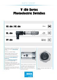
3. V-type Operating Handle<br />
● Appearance (Color N1.5)<br />
● Outside Dimension Diagram<br />
A<br />
Front base<br />
Front plate<br />
Center of Hinge and<br />
Circuit Breaker<br />
Handle<br />
Front plate<br />
TR<br />
I P<br />
PED<br />
O<br />
N<br />
B<br />
90<br />
H<br />
H<br />
OFF<br />
● This handle in conjunction with the breaker main<br />
enables the isolation function effective.<br />
● The safety standards of EN Standards<br />
(EN60204-1) are satisfied.<br />
● Degrees of protection (IEC60529) IP65 is<br />
satisfied standardly.<br />
● OFF-position lock only is available for up to three<br />
commercial padlocks (ø8).<br />
● A door-lock mechanism allows the door to be<br />
opened at OFF-position only.<br />
RESET<br />
16<br />
90<br />
Plate<br />
thickness<br />
1.2–3.2<br />
● Mounting-hole Drilling Dimension Diagram<br />
Center of the<br />
circuit breaker<br />
operating handle<br />
H<br />
C L<br />
54<br />
C<br />
<br />
Maximum F<br />
Circuit breaker Center of the<br />
operating handle<br />
Center of the circuit<br />
breaker operating handle<br />
D<br />
Left<br />
Hinge<br />
H<br />
X<br />
0 or higher (5H+100)<br />
The above illustration shows a view<br />
of the hinges and the circuit breaker<br />
when viewed from the direction of<br />
the load.<br />
● Front Plate Drilling<br />
Dimension Diagram<br />
C L C L<br />
Center of the circuit breaker<br />
C L C L<br />
operating handle<br />
C L ø<br />
H<br />
Center of the<br />
circuit breaker<br />
(Note 1)<br />
X<br />
Circuit<br />
breaker<br />
X<br />
Right<br />
Hinge<br />
Circuit<br />
breaker<br />
C L<br />
ø54<br />
54<br />
G<br />
3-pole<br />
Either M4×0.7<br />
screw or ø5<br />
J<br />
G G<br />
4-pole<br />
Either M4×0.7<br />
screw or ø5<br />
54<br />
Note 1: The drilling at this position is not required for the models of both V2GSW and V2GSWF.<br />
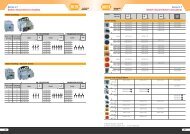
Table 5-17: Summary of Dimensions<br />
Type name<br />
Applicable models<br />
(Note 2) NF32-SW, NF63-CW/SW/HW, NV32-SW<br />
(Note 3) NV63-CW/SW/HW, MB30-SW<br />
V05SWF MB50-CW/SW<br />
<br />
<br />
3P<br />
4P<br />
<br />
A B C D E F G H J<br />
<br />
75 130 44 61 125 25 111<br />
12.5<br />
V1SW<br />
(Note 2)<br />
V1SWF<br />
NF125-CW/SW/HW, NV125-CW/SW/HW<br />
MB100-SW<br />
3P<br />
4P<br />
90 130 44 61<br />
154 518<br />
125 <br />
30 111<br />
<br />
15<br />
V2SW<br />
(Note 2)<br />
V2SWF<br />
NF160-SW/HW, NF250-CW/SW/HW, NV250-CW/SW/HW<br />
NV250-SEW/HEW, MB225-SW<br />
2P, 3P<br />
4P<br />
105 165 46 61<br />
154 518<br />
125 <br />
35 126<br />
<br />
17.5<br />
V2GSW<br />
(Note 2)<br />
V2GSWF<br />
3P<br />
NF125-SGW/HGW, NF160-SGW/HGW, NF250-SGW/HGW 105 165 46 79<br />
4P<br />
172 536<br />
143 <br />
35 126<br />
<br />
17.5<br />
Notes: (1) This hole is not required for two and three poles.<br />
(2) The last letter of “F” of the type designations of V-type operating handles denotes a fixed type. Attach the letters of “4P”<br />
to the end of designation for four-pole models of circuit breaker main body.<br />
(3) Adjustable types can be produced upon request. Please contact us for details.<br />
Remark: (1) You may contact us for details of the V-type operating handle for the U series.<br />
✽ <br />
28