WS Series - autocentrated
WS Series - autocentrated
WS Series - autocentrated

Create successful ePaper yourself
Turn your PDF publications into a flip-book with our unique Google optimized e-Paper software.
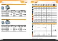
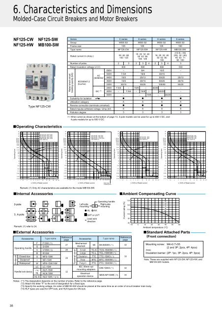
6. Characteristics and Dimensions<br />
Molded-Case Circuit Breakers and Motor Breakers<br />
NF125-CW<br />
NF125-HW<br />
NF125-SW<br />
MB100-SW<br />
Type NF125-CW<br />
<strong>Series</strong> C series S series H series S series<br />
Group <strong>WS</strong>S G2 <strong>WS</strong>S G2 <strong>WS</strong>S G2 <strong>WS</strong>S G2<br />
Frame size 125 125 125 100<br />
Type name NF125-CW NF125-SW NF125-HW MB100-SW<br />
Rated current In (Amp.)<br />
Number of poles 2 3 2 3 4 2 3 4<br />
3<br />
Rated insulation voltage Ui (V)<br />
Rated short-circuit<br />
braking cpacity (kA)<br />
IEC60947-2<br />
(Icu/Ics)<br />
AC<br />
(50/60Hz)<br />
DC ∗1<br />
690V<br />
500V<br />
440V<br />
400V<br />
230V<br />
250V<br />
400V<br />
500V<br />
Suitability for isolation<br />
Utilization category<br />
Reverse connection (terminals unmarked)<br />
Rated impulse withstand voltage Uimp (kV)<br />
Pollution degree<br />
50 63 80<br />
100 125<br />
600<br />
–<br />
7.5/4<br />
10/5<br />
10/5<br />
30/15<br />
7.5/4 –<br />
– 7.5/4<br />
15/8 – 40/20 –<br />
– 15/8 – 40/20<br />
– 15/8 – 40/20<br />
∗1: When wired as shown at the bottom of page 13, 3-pole models can be used for up to 400 V DC, and<br />
4-pole models for up to 500 V DC.<br />
–<br />
●<br />
A<br />
●<br />
8<br />
3<br />
16 20 32 40<br />
50 63 80<br />
100 125<br />
690<br />
8/4<br />
18/9<br />
25/13<br />
30/15<br />
50/25<br />
●<br />
A<br />
●<br />
8<br />
3<br />
16 20 32 40<br />
50 63 80<br />
100<br />
690<br />
10/5<br />
30/15<br />
50/25<br />
50/25<br />
100/50<br />
●<br />
A<br />
●<br />
8<br />
3<br />
(12.5) (16)<br />
(25) 32 (40)<br />
45 63 71<br />
90 100<br />
500<br />
–<br />
–<br />
25/13<br />
30/15<br />
50/25<br />
–<br />
–<br />
–<br />
●<br />
A<br />
●<br />
8<br />
3<br />
■Operating Characteristics<br />
Operating time<br />
4h<br />
2h<br />
1h<br />
30min<br />
20min<br />
14min<br />
10min<br />
6min<br />
4min<br />
2min<br />
1min<br />
30s<br />
20s<br />
10s<br />
5s<br />
2s<br />
1s<br />
0.5s<br />
0.2s<br />
0.1s<br />
0.05s<br />
0.02s<br />
0.01s<br />
Min.<br />
Time-delay trip<br />
NF125-CW 50A~100A<br />
NF125-SW 40A~100A<br />
NF125-HW 40A~100A<br />
MB100-SW 40A~100A<br />
(IEC 60947-2)<br />
Max.<br />
(60A~100A)<br />
Max. (40A~50A)<br />
AC<br />
DC<br />
Max. total<br />
breaking<br />
time<br />
Instantaneous trip<br />
1 1.3 2 3 4 5 6 7 10 15 20 30 40 50<br />
Operating time<br />
4h<br />
2h<br />
1h<br />
30min<br />
20min<br />
14min<br />
10min<br />
6min<br />
4min<br />
2min<br />
1min<br />
30s<br />
20s<br />
10s<br />
5s<br />
2s<br />
1s<br />
0.5s<br />
0.2s<br />
0.1s<br />
0.05s<br />
0.02s<br />
0.01s<br />
Min.<br />
Time-delay trip<br />
Max.<br />
NF125-SW 16A~20A<br />
NF125-HW 16A~20A<br />
MB125-SW 12.5A~20A<br />
(IEC 60947-2)<br />
1 1.3 2 3 4 5 6 7 10 15 20 30 40 50 60 70<br />
AC<br />
DC<br />
Instantaneous trip<br />
Operating time<br />
4h<br />
2h<br />
1h<br />
30min<br />
20min<br />
14min<br />
10min<br />
6min<br />
4min<br />
2min<br />
1min<br />
30s<br />
20s<br />
10s<br />
5s<br />
2s<br />
1s<br />
0.5s<br />
0.2s<br />
0.1s<br />
0.05s<br />
0.02s<br />
0.01s<br />
Min.<br />
NF125-CW 125A<br />
NF125-SW 125A<br />
(IEC 60947-2)<br />
AC<br />
Max.<br />
DC<br />
Max. total<br />
breaking time<br />
Operating time<br />
4h<br />
2h<br />
1h<br />
30min<br />
20min<br />
14min<br />
10min<br />
6min<br />
4min<br />
2min<br />
1min<br />
30s<br />
20s<br />
10s<br />
5s<br />
2s<br />
1s<br />
0.5s<br />
0.2s<br />
0.1s<br />
0.05s<br />
0.02s<br />
Time-delay trip<br />
Instantaneous trip<br />
Time-delay trip<br />
Instantaneous trip<br />
0.01s<br />
1 1.3 2 3 4 5 6 7 10 15 20 30 40 50 1 1.3 2 3 4 5 6 7 10 15 20 30 40 50<br />
Min.<br />
NF125-SW 32A<br />
NF63-HRW 32A<br />
NF125-HW 32A<br />
(IEC 60947-2)<br />
Max.<br />
AC<br />
DC<br />
Max. total<br />
breaking<br />
time<br />
100% of Rated current<br />
100% of Rated current<br />
Max. total<br />
breaking time<br />
100% of Rated current 100% of Rated current<br />
Remark: (1) Only AC characteristics are available for the model MB100-SW.<br />
■Internal Accessories<br />
■Ambient Compensating Curve<br />
2-pole<br />
3, 4-pole<br />
Remark: (1) refer to 24.<br />
■External Accessories<br />
Accessories<br />
Operating handle<br />
Enclosure<br />
Closed-box<br />
Dustproof<br />
Waterproof<br />
Handle lock device<br />
F F1SW (*1)<br />
S<br />
V<br />
R<br />
S<br />
I<br />
W<br />
LC<br />
()<br />
HL<br />
HL-S<br />
<br />
S1SW<br />
V1SW ()<br />
R1SW<br />
NFS-1SW<br />
NFl-1SW<br />
NFW-1SW/1HW<br />
LC-1SW<br />
HLF-1SW<br />
HLN-1SW<br />
HLS-1SW ()()<br />
Reference<br />
page<br />
27<br />
28<br />
29<br />
32<br />
Terminal cover<br />
Left-side<br />
mounting<br />
AL<br />
Accessories<br />
Mechanical<br />
interlock<br />
AX<br />
SHT or UVT<br />
Lead wire<br />
direction<br />
Operating handle<br />
Right-side<br />
mounting<br />
<br />
Ml Ml-05SW3 () 32<br />
TC-S TCS-1SW3W ()<br />
TC-L TCL-1SW3W ()<br />
TTC TTC-1SW3 ()<br />
BTC BTC-1SW3W ()<br />
PTC PTC-1SW3W ()<br />
IEC 35mm rail<br />
mounting adapters<br />
Electrical<br />
operation device<br />
30<br />
DIN-1SW3 () 32<br />
MDS-NF1SWE ()<br />
Current rating (%)<br />
30<br />
130<br />
120<br />
110<br />
100<br />
90<br />
80<br />
–10<br />
Reference<br />
page<br />
Notes: (*1) The designation depends on the number of poles. Refer to the reference page.<br />
(*2) Attach the letter "F" to the end of designation for a fixed type.<br />
(*3) Specify the working voltage. An order of MB100-SW should be placed at the same time as an order of circuit breaker main body.<br />
(*4) HLF types are used for OFF-lock, and HLN types for ON-lock.<br />
Rated ambient<br />
0 10 20 30 40 50 60<br />
Ambient temperature (°C)<br />
■Standard Attached Parts<br />
(Front connection)<br />
Mounting screw: M4×0.7×55<br />
(2 and 3P: 2pcs, 4P: 4pcs)<br />
(Note)<br />
Insulation barrier: (2P: 1pc, 3P: 2pcs, 4P: 3pcs)<br />
Note: These are supplied with NF125-SW, NF125-HW, and<br />
MB100-SW models.<br />
35