X-431 GDS Sensorbox Manual_en.pdf - OBD China
X-431 GDS Sensorbox Manual_en.pdf - OBD China
X-431 GDS Sensorbox Manual_en.pdf - OBD China

Create successful ePaper yourself
Turn your PDF publications into a flip-book with our unique Google optimized e-Paper software.
V1.00.001<br />
2012-05-07
LAUNCH<br />
X<strong>431</strong> <strong>GDS</strong> <strong>S<strong>en</strong>sorbox</strong> <strong>Manual</strong><br />
All rights reserved! No part of this publication may be reproduced,<br />
stored in a retrieval system or transmitted, in any form or by any means<br />
of electronic, mechanical, photocopying and recording or otherwise,<br />
without the prior writt<strong>en</strong> permission of LAUNCH.<br />
This manual is designed only for the use of this unit. LAUNCH is not<br />
responsible for any use of this manual on the other units.<br />
The manual and all the samples herein can be changed without prior<br />
notice. Neither LAUNCH nor its affiliates shall be liable to the purchaser<br />
of this unit or third parties for damages, losses, costs or exp<strong>en</strong>ses<br />
incurred by purchaser or third parties as a result of: accid<strong>en</strong>t, misuse, or<br />
abuse of this unit, or unauthorized modifications, repairs, or alterations to<br />
this unit, or failure to strictly comply with LAUNCH operating and<br />
maint<strong>en</strong>ance instructions.<br />
LAUNCH shall not be liable for any damages or problems arising from<br />
the use of any options or any consumable products other than those<br />
designated as Original LAUNCH Products or LAUNCH Approved<br />
Products<br />
Notice: other product names used herein are for id<strong>en</strong>tification purposes<br />
only and may be trademarks of their respective owners. LAUNCH<br />
disclaims any and all rights in those marks.<br />
This device is only for professional technicians and maint<strong>en</strong>ance<br />
personnel.<br />
ii
LAUNCH<br />
X<strong>431</strong> <strong>GDS</strong> <strong>S<strong>en</strong>sorbox</strong> <strong>Manual</strong><br />
Registered Trademark<br />
LAUNCH is a registered trademark of LAUNCH TECH. CO., LTD.<br />
(LAUNCH) in <strong>China</strong> and other countries. In other countries where any of<br />
the LAUNCH trademarks, service marks, domain names, logos and<br />
company names is not registered, LAUNCH claims other rights<br />
associated with unregistered trademarks, service marks, domain names,<br />
logos and company names. Other products or company names referred<br />
to in this manual may be trademarks of their respective owners. You may<br />
not use any trademarks, service marks, domain names, logos or<br />
company name of LAUNCH or any third party without permission from<br />
the owner of the applicable trademarks, service marks, domain names,<br />
logos or company name. You may visit LAUNCH at<br />
http://www.cnlaunch.com for the information of Launch's and the other<br />
specialized diagnostic tools, or contact Launch by visiting<br />
http://www.X<strong>431</strong>.com or writing to Customer C<strong>en</strong>ter, LAUNCH TECH.<br />
CO., LTD., Launch Industrial Park, North of Wuhe Av<strong>en</strong>ue, Banxuegang,<br />
Bantian, Longgang, Sh<strong>en</strong>zh<strong>en</strong>, Guangdong. P.R. <strong>China</strong>, to request<br />
writt<strong>en</strong> permission to use materials on this manual for purposes or for all<br />
other questions relating to this manual.<br />
iii
LAUNCH<br />
X<strong>431</strong> <strong>GDS</strong> <strong>S<strong>en</strong>sorbox</strong> <strong>Manual</strong><br />
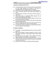
Precaution on Operation<br />
• The appliance is a sophisticated electronic device, never have it<br />
clashed wh<strong>en</strong> in use.<br />
• Main unit scre<strong>en</strong> may flash at the mom<strong>en</strong>t of <strong>en</strong>gine ignition, which<br />
is normal.<br />
• You may unplug the main unit if the program can not be actuated or<br />
confused scre<strong>en</strong> occurs. Plug again to continue the operation.<br />
• Make sure the appliance is properly connected to the DLC to avoid<br />
communication interruptions.<br />
• During operation, keep the scre<strong>en</strong> upward and leveled.<br />
• Be careful wh<strong>en</strong> plugging and unplugging the main cable and<br />
diagnostic connector. Tight<strong>en</strong> the screw before operation to avoid<br />
unexpected disconnecting and/or damage to the port.<br />
• Handle with care. Avoid collision. Unplug the power after operation.<br />
• Do not insert or pull the <strong>GDS</strong> card wh<strong>en</strong> the main unit is powered<br />
on.<br />
• After the operation, the stylus shall be inserted into the hole on the<br />
back of the main unit, and put away the cable and connector, etc<br />
accessories to the box to avoid the lost.<br />
• Unplug the power cable by holding the connector, not the cable<br />
itself.<br />
iv
LAUNCH<br />
X<strong>431</strong> <strong>GDS</strong> <strong>S<strong>en</strong>sorbox</strong> <strong>Manual</strong><br />
Cont<strong>en</strong>ts<br />
1 FOREWORD ................................................................................ 2<br />
1.1 PRODUCT SUMMARY ................................................................. 2<br />
1.2 PRODUCT FEATURES.................................................................. 3<br />
1.3 PRODUCT FUNCTION ................................................................. 3<br />
1.4 TECHNICAL PARAMETERS.......................................................... 3<br />
2 STRUCTURE AND ACCESSORIES.......................................... 5<br />
2.1 SENSORBOX STRUCTURE........................................................... 5<br />
2.2 SENSORBOX ACCESSORIES ........................................................ 6<br />
3 SENSOR SIMULATION.............................................................. 8<br />
3.1 CONNECTIONS .......................................................................... 8<br />
3.2 SIMULATION TEST ..................................................................... 8<br />
3.2.1 DC voltage simulation .......................................................9<br />
3.2.2 Constant frequ<strong>en</strong>cy simulation ........................................11<br />
3.2.3 Predefinition waveform simulation..................................12<br />
3.2.4 Hand-drawn waveform ....................................................15<br />
3.2.5 Precautions on checking vehicle s<strong>en</strong>sor ..........................17<br />
4 AUTO MULTIMETER .............................................................. 20<br />
4.1 MAIN MENU ........................................................................... 20<br />
4.2 TEST SAMPLE .......................................................................... 21<br />
1
LAUNCH<br />
X<strong>431</strong> <strong>GDS</strong> <strong>S<strong>en</strong>sorbox</strong> <strong>Manual</strong><br />
1 Foreword<br />
1.1 Product summary<br />
X-<strong>431</strong> <strong>GDS</strong> is a new g<strong>en</strong>eration of sophisticated automotive<br />
diagnostic product with colorful scre<strong>en</strong> and powerful functions<br />
developed by LAUNCH.<br />
It provides an optional function of automotive s<strong>en</strong>sor simulation test.<br />
“S<strong>en</strong>sor simulation test” function is specially designed to diagnose<br />
and simulate vehicle s<strong>en</strong>sor faults quickly and conv<strong>en</strong>i<strong>en</strong>tly,<br />
including "DC voltage simulation", "Constant frequ<strong>en</strong>cy simulation",<br />
"Predefinition waveform simulation", and "Hand-drawn waveform<br />
simulation".<br />
Vehicle s<strong>en</strong>sors are the signal input devices for electrical control<br />
systems, which can transform all kinds of running parameters, such<br />
as vehicle speed, coolant temperature, <strong>en</strong>gine RPM, air flow, throttle<br />
op<strong>en</strong>ing, etc., into the electronic signal for the vehicle computer who<br />
can optimize the <strong>en</strong>gine running status per the above-m<strong>en</strong>tioned<br />
parameters to keep the <strong>en</strong>gine working in a prime status.<br />
Meanwhile, it integrates the functions of automobile multimeter,<br />
which <strong>en</strong>ables users to perform voltage, resistance, frequ<strong>en</strong>cy test.<br />
(The function utilizes the same hardware device as the s<strong>en</strong>sor<br />
module)<br />
2
LAUNCH<br />
X<strong>431</strong> <strong>GDS</strong> <strong>S<strong>en</strong>sorbox</strong> <strong>Manual</strong><br />
1.2 Product features<br />
• DC voltage simulation<br />
• Constant frequ<strong>en</strong>cy simulation<br />
• Predefinition waveform simulation<br />
• Hand-drawn waveform simulation<br />
1.3 Product function<br />
Provides automotive s<strong>en</strong>sor simulation test and multimeter test<br />
function.<br />
1.4 Technical parameters<br />
<strong>S<strong>en</strong>sorbox</strong><br />
Parameters<br />
Scope<br />
Precision ±5%<br />
Voltage range<br />
-12V~+12V<br />
Max output curr<strong>en</strong>t<br />
70mA<br />
Predefined frequ<strong>en</strong>cy range<br />
0~150Hz<br />
Square-wave signal pulse frequ<strong>en</strong>cy 0~15KHz<br />
Square-wave signal duty ratio<br />
10%~90%<br />
3
LAUNCH<br />
X<strong>431</strong> <strong>GDS</strong> <strong>S<strong>en</strong>sorbox</strong> <strong>Manual</strong><br />
Multimeter<br />
Parameters<br />
Scope<br />
Precision ±5%<br />
Voltage test<br />
Testing range DC-400V~+400V<br />
Input<br />
10Mohm<br />
impedance<br />
Resistance test Testing range 0~40Mohm<br />
Frequ<strong>en</strong>cy test Testing range 0~25KHz<br />
Input<br />
impedance<br />
1000Gohm<br />
Input voltage 1~12V<br />
4
LAUNCH<br />
X<strong>431</strong> <strong>GDS</strong> <strong>S<strong>en</strong>sorbox</strong> <strong>Manual</strong><br />
2 Structure and Accessories<br />
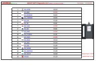
2.1 <strong>S<strong>en</strong>sorbox</strong> structure<br />
Fig. 2-1 Structural diagram of <strong>S<strong>en</strong>sorbox</strong><br />
Table 2-1 shows the ports and indicators for X-<strong>431</strong> <strong>GDS</strong> s<strong>en</strong>sorbox<br />
No. Name Description<br />
1 VΩHz Measuring terminal of multimeter<br />
2 COM Common terminal of multimeter<br />
3 Power interface Connect DC 12V power via the power<br />
adaptor.<br />
4 B-shaped USB Connect main unit via USB connect wire<br />
5
LAUNCH<br />
X<strong>431</strong> <strong>GDS</strong> <strong>S<strong>en</strong>sorbox</strong> <strong>Manual</strong><br />
interface<br />
as a separate USB device<br />
5 Power indicator S<strong>en</strong>sor power indicator, which will be<br />
steady red after the s<strong>en</strong>sor module is<br />
powered up.<br />
6 Indicator for Indicator (Gre<strong>en</strong>) for s<strong>en</strong>ding data to<br />
s<strong>en</strong>ding data to<br />
main unit.<br />
main unit<br />
7 Indicator for Indicator (Gre<strong>en</strong>) for receiving data from<br />
receiving data main unit.<br />
from main unit<br />
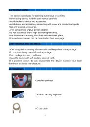
2.2 <strong>S<strong>en</strong>sorbox</strong> accessories<br />
X-<strong>431</strong> <strong>GDS</strong> s<strong>en</strong>sorbox accessories include s<strong>en</strong>sor test cable, probe<br />
etc. See Table 2-2.<br />
As the product configuration can be differ<strong>en</strong>t, the accessories<br />
included with the product may differ from the accessories listed on<br />
this manual. Please see the packing list attached to the product for<br />
the detailed accessories.<br />
Table 2-2 Accessory checklist<br />
No. Name Picture<br />
1 s<strong>en</strong>sor test cable<br />
6
LAUNCH<br />
X<strong>431</strong> <strong>GDS</strong> <strong>S<strong>en</strong>sorbox</strong> <strong>Manual</strong><br />
2 S<strong>en</strong>sor probe<br />
3 Multimeter probe<br />
4 Electric control convertor<br />
cable1<br />
5 Electric control convertor<br />
cable 2<br />
6 Electric control convertor<br />
cable 3<br />
7 Electric control convertor<br />
cable 4<br />
7
LAUNCH<br />
X<strong>431</strong> <strong>GDS</strong> <strong>S<strong>en</strong>sorbox</strong> <strong>Manual</strong><br />
3 S<strong>en</strong>sor Simulation<br />
3.1 Connections<br />
1. Firstly, power on the main unit (Connect one <strong>en</strong>d of the power<br />
adaptor into the power interface of main unit, and the other <strong>en</strong>d<br />
to the DC 12V power supply. Alternatively it can be also<br />
powered by cigarette lighter cable and double clip power cord);<br />
2. Plug one <strong>en</strong>d of the s<strong>en</strong>sor test cable (black) into the "COM"<br />
interface of the s<strong>en</strong>sorbox, th<strong>en</strong> connect the other <strong>en</strong>d to the<br />
test probe or electric control convertor cable;<br />
3. Connect one <strong>en</strong>d of the s<strong>en</strong>sor test cable (red) into the "VΩHz"<br />
interface of the s<strong>en</strong>sorbox, and th<strong>en</strong> connect the other <strong>en</strong>d to<br />
the test probe or electric control convertor cable.<br />
Note: Choose corresponding cables and test probes according to<br />
differ<strong>en</strong>t terminal.<br />
3.2 Simulation test<br />
Simulation test <strong>en</strong>ables users to exactly judge if the s<strong>en</strong>sor is good<br />
or not to avoid replacing compon<strong>en</strong>ts blindly. For example, the<br />
trouble code indicates the fault is in water temperature s<strong>en</strong>sor itself.<br />
But we need to confirm whether the fault results from water<br />
temperature s<strong>en</strong>sor or the connections betwe<strong>en</strong> ECU and s<strong>en</strong>sors,<br />
or ECU itself. In this case, we can make full use of simulation test to<br />
input the signal of simulating water temperature s<strong>en</strong>sor, instead of<br />
8
LAUNCH<br />
X<strong>431</strong> <strong>GDS</strong> <strong>S<strong>en</strong>sorbox</strong> <strong>Manual</strong><br />
water temperature s<strong>en</strong>sor, to the microcomputer. If the <strong>en</strong>gine works<br />
better and the fault vanishes, the fault is in the water temperature<br />
s<strong>en</strong>sor. If the fault still occurs, input the signal to the corresponding<br />
terminals of ECU. Consequ<strong>en</strong>tly, if the fault disappears, the fault lies<br />
in the connection betwe<strong>en</strong> water temperature s<strong>en</strong>sor and ECU,<br />
otherwise, the fault exists in ECU.<br />
After all connections are properly made (refer to Chapter 3.1 for<br />
details), power on and <strong>en</strong>ter the function m<strong>en</strong>u interface, th<strong>en</strong> click<br />
"S<strong>en</strong>sor simulation" to <strong>en</strong>ter the test selection scre<strong>en</strong>. See Fig. 3-1.<br />
Fig.3-1<br />
3.2.1 DC voltage simulation<br />
In Fig. 3-1, select [DC voltage simulation], th<strong>en</strong> click [Enter] button,<br />
the interface is shown as Fig. 3-2:<br />
9
LAUNCH<br />
X<strong>431</strong> <strong>GDS</strong> <strong>S<strong>en</strong>sorbox</strong> <strong>Manual</strong><br />
Fig.3-2<br />
In Fig. 3-2, click the "Voltage" button on right side, a pull-down m<strong>en</strong>u<br />
of "Voltage +" and "voltage -" pops up, which allows you to adjust the<br />
output voltage value. After selecting the desired voltage based on<br />
the working characteristics of s<strong>en</strong>sor, click the "Start" button, th<strong>en</strong><br />
the X-<strong>431</strong> <strong>GDS</strong> will begin to output the simulation voltages. Please<br />
note the red probe is the output terminal of simulation voltage.<br />
Button descriptions:<br />
[System]: includes: shows desktop, views curr<strong>en</strong>t version, and exits<br />
the program.<br />
[Help]: guides you on how to operate the curr<strong>en</strong>t interface.<br />
[Voltage]: adjusts the voltage value through "Voltage +" and<br />
"voltage -".<br />
10
LAUNCH<br />
X<strong>431</strong> <strong>GDS</strong> <strong>S<strong>en</strong>sorbox</strong> <strong>Manual</strong><br />
[Start]: confirms the curr<strong>en</strong>t operation.<br />
[Return]: returns to the previous interface.<br />
3.2.2 Constant frequ<strong>en</strong>cy simulation<br />
This option <strong>en</strong>ables you to simulate the square wave signal of pulse<br />
frequ<strong>en</strong>cy of 0.1 ~ 15 kHz, amplitude range of -5V ~ +5 V and duty<br />
cycle 10% ~ 90%.<br />
In Fig. 3-1, select "Constant frequ<strong>en</strong>cy simulation", and th<strong>en</strong> click<br />
[Enter] to <strong>en</strong>ter a scre<strong>en</strong>, similar to Fig. 3-3.<br />
Fig.3-3<br />
Button descriptions:<br />
[Freq.]: adjusts frequ<strong>en</strong>cy<br />
[Voltage]: displays voltage value of curr<strong>en</strong>t square wave signal<br />
[DCR]: displays duty cycle ratio of curr<strong>en</strong>t square wave signal<br />
11
LAUNCH<br />
X<strong>431</strong> <strong>GDS</strong> <strong>S<strong>en</strong>sorbox</strong> <strong>Manual</strong><br />
After setting, click [Start] to perform the test.<br />
3.2.3 Predefinition waveform simulation<br />
X-<strong>431</strong> <strong>GDS</strong> provides some common s<strong>en</strong>sor waveforms which have<br />
be<strong>en</strong> predefined to facilitate users to simulate s<strong>en</strong>sor signals. As<br />
long as you call out the predefined waveform (after "s<strong>en</strong>sor type"<br />
and "wave type" being selected), the simulation waveform will be<br />
displayed on the left coordinates. Just click "Start" to start simulating<br />
output of corresponding s<strong>en</strong>sor waveform and no more parameters<br />
of simulation waveform are required to set.<br />
In Fig. 3-1, select "Predefinition waveform simulation", th<strong>en</strong> click<br />
[Enter] to <strong>en</strong>ter the scre<strong>en</strong> shown as Fig.3-4.<br />
Fig.3-4<br />
Here, click [Sel.Wv.] button, a scre<strong>en</strong> similar to Fig. 3-5 will appear.<br />
12
LAUNCH<br />
X<strong>431</strong> <strong>GDS</strong> <strong>S<strong>en</strong>sorbox</strong> <strong>Manual</strong><br />
Fig.3-5<br />
In Fig. 3-5, the setting items shown on the left stands for s<strong>en</strong>sor<br />
types.<br />
ECT: Coolant Temperature S<strong>en</strong>sor<br />
EVP: EGR Valve Position S<strong>en</strong>sor<br />
HO2S: Heated Oxyg<strong>en</strong> S<strong>en</strong>sor<br />
IAT: Intake Air Temperature S<strong>en</strong>sor<br />
MAF: Mass Air Flow S<strong>en</strong>sor<br />
MAP: Manifold Absolute Pressure S<strong>en</strong>sor<br />
TP: Throttle Position S<strong>en</strong>sor<br />
VAF: Volume Air Flow S<strong>en</strong>sor<br />
13
LAUNCH<br />
X<strong>431</strong> <strong>GDS</strong> <strong>S<strong>en</strong>sorbox</strong> <strong>Manual</strong><br />
VSS: Vehicle Speed S<strong>en</strong>sor<br />
For example, click "ECT" – "Warm (NTC Thermistor)" in Fig. 3-5, the<br />
right scre<strong>en</strong> will display the waveform of the s<strong>en</strong>sor. See Fig. 3-6.<br />
Fig.3-6<br />
In Fig. 3-6, click [OK] button, th<strong>en</strong> the pre-defined waveform has<br />
be<strong>en</strong> set. See Fig. 3-7.<br />
14
LAUNCH<br />
X<strong>431</strong> <strong>GDS</strong> <strong>S<strong>en</strong>sorbox</strong> <strong>Manual</strong><br />
Fig.3-7<br />
In Fig. 3-7, click [Start] button to perform simulation test.<br />
Button descriptions:<br />
[System]: includes: shows desktop, views curr<strong>en</strong>t version, and exits<br />
the program.<br />
[Help]: provides the operational guide for curr<strong>en</strong>t interface.<br />
[Sel.Wv.]: selects waveforms under differ<strong>en</strong>t working status.<br />
[Start]: continues the following operation.<br />
[Return]: returns to the previous interface.<br />
3.2.4 Hand-drawn waveform<br />
This option offers great conv<strong>en</strong>i<strong>en</strong>ce for users to simulate special<br />
15
LAUNCH<br />
X<strong>431</strong> <strong>GDS</strong> <strong>S<strong>en</strong>sorbox</strong> <strong>Manual</strong><br />
waveform or fault wave. Users only draw the shape of waveform<br />
which needs to be simulated in left drawing area, and th<strong>en</strong> configure<br />
some parameters on the right, namely high level, lower level, and<br />
period of waveform, th<strong>en</strong> click [Start], X<strong>431</strong> <strong>GDS</strong> will output a<br />
waveform as desired.<br />
Warning:<br />
Just draw a complete periodic waveform (wh<strong>en</strong> it is outputted,<br />
the system will regard the waveform in the drawing area as a<br />
periodic one). Users should draw an as large as wave in<br />
drawing zone so that the system can sample more points to<br />
reduce tolerance. While drawing, just pay att<strong>en</strong>tion to the shape<br />
of waveform, high level, low level and period can be ignored,<br />
which can be set in the right parameter setting section.<br />
In Fig. 3-1, select "Hand-drawn waveform simulation", and th<strong>en</strong> click<br />
[Enter], a scre<strong>en</strong> similar to Fig. 3-8 will appear.<br />
16
LAUNCH<br />
X<strong>431</strong> <strong>GDS</strong> <strong>S<strong>en</strong>sorbox</strong> <strong>Manual</strong><br />
Fig.3-8<br />
Button descriptions:<br />
[System]: includes: shows desktop, views curr<strong>en</strong>t version, and exits<br />
the program.<br />
[Help]: provides the operational guide for curr<strong>en</strong>t interface.<br />
[Setup]: includes functions of "P<strong>en</strong>cil", "Eraser", and "Empty".<br />
[Ref.]: clicks to call out the predefined waveform for refer<strong>en</strong>ce.<br />
[Start]: continues the following operation.<br />
[Return]: returns to the previous interface.<br />
3.2.5 Precautions on checking vehicle s<strong>en</strong>sor<br />
• Hold the connector wh<strong>en</strong> plugging or unplugging it. Do not pull<br />
the cable for unplugging.<br />
• At first check the fuse, fusible line and terminals. Th<strong>en</strong> check<br />
17
LAUNCH<br />
X<strong>431</strong> <strong>GDS</strong> <strong>S<strong>en</strong>sorbox</strong> <strong>Manual</strong><br />
others after eliminating these faults.<br />
• Wh<strong>en</strong> measuring voltage, the ignition switch should be on and<br />
the battery voltage should not be less than 11V.<br />
• Wh<strong>en</strong> measuring voltage, please shake the lead lightly in the<br />
vertical and horizontal direction for more precision.<br />
• Wh<strong>en</strong> checking whether there is op<strong>en</strong> in the line, disconnect<br />
the CEU and the relevant s<strong>en</strong>sor at first, th<strong>en</strong> measure the<br />
resistance among the ports of s<strong>en</strong>sor in order to determine<br />
whether op<strong>en</strong>-circuit / contact fault exists or not.<br />
• Wh<strong>en</strong> checking if there is a short in the line, please disconnect<br />
the CEU and the relevant s<strong>en</strong>sor, th<strong>en</strong> measure the resistance<br />
value of the ports betwe<strong>en</strong> the connected port and the vehicle<br />
body. If the resistance value is more than 1MΩ, no fault occurs.<br />
• Before disassembling the <strong>en</strong>gine electrical control system cable,<br />
cut off the power supply, that is, turn the ignition switch OFF and<br />
disconnect the cables on the battery poles.<br />
• Contact the test probe and the two terminals/ the two leads to<br />
be measured wh<strong>en</strong> measuring the voltage betwe<strong>en</strong> the two<br />
terminals or the two leads.<br />
• Contact the red test probe to the terminal/ the cable to be<br />
measured, and the black probe to the ground wh<strong>en</strong> measuring<br />
voltage of one terminal/ one cable.<br />
18
LAUNCH<br />
X<strong>431</strong> <strong>GDS</strong> <strong>S<strong>en</strong>sorbox</strong> <strong>Manual</strong><br />
• Wh<strong>en</strong> checking the continuity of the terminals, contacts and<br />
leads, the method for measuring their resistances can be used<br />
• Check the faults in the terminals of the CEU to s<strong>en</strong>sors, relays,<br />
etc.<br />
• There are two test probes in the testing wire. The black one is<br />
the common signal terminal (signal GND); the red one is the<br />
input terminal for voltage, resistance, and frequ<strong>en</strong>cy test and<br />
output terminal for simulation voltage, simulation frequ<strong>en</strong>cy and<br />
oxyg<strong>en</strong> s<strong>en</strong>sor. Please choose the correct probes to match the<br />
differ<strong>en</strong>t terminals.<br />
19
LAUNCH<br />
X<strong>431</strong> <strong>GDS</strong> <strong>S<strong>en</strong>sorbox</strong> <strong>Manual</strong><br />
4 Auto Multimeter<br />
4.1 Main M<strong>en</strong>u<br />
After connecting main unit and the s<strong>en</strong>sorbox as m<strong>en</strong>tioned above,<br />
power on the multimeter and <strong>en</strong>ter the function m<strong>en</strong>u interface, click<br />
"Multimeter" to display the test m<strong>en</strong>u. See Fig. 4-1.<br />
Fig.4-1<br />
Click the desired test as shown on Fig.4-1 to perform related test.<br />
Take Voltage Test as an example.<br />
Select "Voltage test", and th<strong>en</strong> click [Enter] to <strong>en</strong>ter Fig. 4-2.<br />
20
LAUNCH<br />
X<strong>431</strong> <strong>GDS</strong> <strong>S<strong>en</strong>sorbox</strong> <strong>Manual</strong><br />
Fig.4-2<br />
Button descriptions:<br />
[System]: includes: shows desktop, view curr<strong>en</strong>t version and exit<br />
the program.<br />
[Help]: views help information for curr<strong>en</strong>t operations.<br />
[Set]: includes: "Zoom in", "Zoom out", "Up", "Down", "Cursor", and<br />
"clear".<br />
[Start]: begins or stops the testing process.<br />
[Return]: return to the previous interface.<br />
4.2 Test sample<br />
Knock s<strong>en</strong>sor testing<br />
(1) Resistance test for knock s<strong>en</strong>sor<br />
21
LAUNCH<br />
X<strong>431</strong> <strong>GDS</strong> <strong>S<strong>en</strong>sorbox</strong> <strong>Manual</strong><br />
Switch ignition "OFF", unplug the wire connector of knock s<strong>en</strong>sor,<br />
test the resistance betwe<strong>en</strong> the wire terminal and the case of knock<br />
s<strong>en</strong>sor with "Resistance test" function, it shall be ∞(disconnected),<br />
and if it is 0Ω(conductive), which means the knock s<strong>en</strong>sor shall be<br />
replaced. For the magnetostriction knock s<strong>en</strong>sor, it can also test the<br />
resistance by the "Resistance measurem<strong>en</strong>t" function; the resistance<br />
shall be compliant with the specified value (see specific service<br />
manual for the detailed data), otherwise, the knock s<strong>en</strong>sor shall be<br />
replaced.<br />
(2) Checking for the output signal of knock s<strong>en</strong>sor<br />
Unplug the wire connector of knock s<strong>en</strong>sor, check voltage betwe<strong>en</strong><br />
knock s<strong>en</strong>sor connector terminal and ground wire of knock, it should<br />
be output pulse voltage; otherwise, the knock s<strong>en</strong>sor shall be<br />
replaced.<br />
Coolant temperature s<strong>en</strong>sor testing<br />
(1) Resistance test for coolant temperature s<strong>en</strong>sor<br />
On vehicle testing:<br />
Switch ignition "OFF" and unplug the wire connector of coolant<br />
temperature s<strong>en</strong>sor, th<strong>en</strong> use the "Resistance measurem<strong>en</strong>t" to test<br />
the Resistance betwe<strong>en</strong> two terminals of s<strong>en</strong>sor. The relationship<br />
betwe<strong>en</strong> the resistance and the temperature is in inversely<br />
proportion (negative temperature coeffici<strong>en</strong>t), which shall be less<br />
than 1kΩ during warming up.<br />
22
LAUNCH<br />
X<strong>431</strong> <strong>GDS</strong> <strong>S<strong>en</strong>sorbox</strong> <strong>Manual</strong><br />
Indep<strong>en</strong>d<strong>en</strong>t testing:<br />
Unplug the wire connector of coolant temperature s<strong>en</strong>sor, th<strong>en</strong><br />
remove the s<strong>en</strong>sor from the <strong>en</strong>gine; place the s<strong>en</strong>sor into a breaker<br />
with water and heat the water, th<strong>en</strong> use the "Resistance<br />
measurem<strong>en</strong>t" to test the Resistance betwe<strong>en</strong> two terminals of<br />
coolant temperature s<strong>en</strong>sor at differ<strong>en</strong>t water temperature.<br />
Compared the measured value with the standard value, if the<br />
Resistance is not compliant with the standard, th<strong>en</strong> the coolant<br />
temperature s<strong>en</strong>sor shall be replaced.<br />
(2) Output signal voltage testing for coolant temperature s<strong>en</strong>sor<br />
After installing the coolant temperature s<strong>en</strong>sor, plug the wire<br />
connector of s<strong>en</strong>sor, and th<strong>en</strong> switch ignition ON, test the output<br />
signal voltage betwe<strong>en</strong> the two terminals of wire connector. The<br />
tested voltage shall be in inverse proportional with the coolant<br />
temperature. Wh<strong>en</strong> the harness of coolant temperature s<strong>en</strong>sor is<br />
disconnected, the voltage shall be about 5V if the ignition switch is<br />
ON.<br />
23
LAUNCH<br />
X<strong>431</strong> <strong>GDS</strong> <strong>S<strong>en</strong>sorbox</strong> <strong>Manual</strong><br />
Warranty<br />
THIS WARRANTY IS EXPRESSLY LIMITED TO PERSONS WHO<br />
PURCHASE LAUNCH PRODUCTS FOR PURPOSES OF RESALE<br />
OR USE IN THE ORDINARY COURSE OF THE BUYER’S<br />
BUSINESS.<br />
LAUNCH electronic product is warranted against defects in materials<br />
and workmanship for one year (12 months) from date of delivery to<br />
the user. This warranty does not cover any part that has be<strong>en</strong><br />
abused, altered, used for a purpose other than for which it was<br />
int<strong>en</strong>ded, or used in a manner inconsist<strong>en</strong>t with instructions<br />
regarding use. The exclusive remedy for any automotive meter<br />
found to be defective is repair or replacem<strong>en</strong>t, and LAUNCH shall<br />
not be liable for any consequ<strong>en</strong>tial or incid<strong>en</strong>tal damages. Final<br />
determination of defects shall be made by LAUNCH in accordance<br />
with procedures established by LAUNCH. No ag<strong>en</strong>t, employee, or<br />
repres<strong>en</strong>tative of LAUNCH has any authority to bind LAUNCH to any<br />
affirmation, repres<strong>en</strong>tation, or warranty concerning LAUNCH<br />
automotive meters, except as stated herein.<br />
Disclaimer<br />
THE ABOVE WARRANTY IS IN LIEU OF ANY OTHER WARRANTY,<br />
EXPRESSED OR IMPLIED, INCLUDING ANY WARRANTY OF<br />
MERCHANTABILITY OR FITNESS FOR A PARTICULAR<br />
PURPOSE.<br />
24
LAUNCH<br />
X<strong>431</strong> <strong>GDS</strong> <strong>S<strong>en</strong>sorbox</strong> <strong>Manual</strong><br />
Order Information<br />
Replaceable and optional parts can be ordered directly from your<br />
LAUNCH authorized tool supplier. Your order should include the<br />
following information:<br />
1. Quantity<br />
2. Part number<br />
3. Item description<br />
Customer Service Departm<strong>en</strong>t<br />
If you have any questions on the operation of the unit, please call:<br />
+86-755-84528767<br />
If your unit requires repair service, return it to the manufacturer with<br />
a copy of the sales receipt and a note describing the problem. If the<br />
unit is determined to be in warranty, it will be repaired or replaced at<br />
no charge. If the unit is determined to be out of warranty, it will be<br />
repaired for a nominal service charge plus return freight. S<strong>en</strong>d the<br />
unit prepaid to:<br />
Attn: Customer Service Departm<strong>en</strong>t<br />
LAUNCH TECH. CO., LTD.<br />
Launch Industrial Park,<br />
North of Wuhe Av<strong>en</strong>ue,<br />
Banxuegang, Bantian,<br />
Longgang, Sh<strong>en</strong>zh<strong>en</strong>, Guangdong<br />
P.R.<strong>China</strong>, 518129<br />
Launch website: http: //www. cnlaunch.com<br />
25
Statem<strong>en</strong>t: LAUNCH reserves the rights to make any change to product<br />
designs and specifications without notice. The actual object may differ a<br />
little from the descriptions in the manual in physical appearance, color<br />
and configuration. We have tried our best to make the descriptions and<br />
illustrations in the manual as accurate as possible, and defects are<br />
inevitable, if you have any question, please contact local dealer or<br />
after-sale service c<strong>en</strong>ter of LAUNCH, LAUNCH does not bear any<br />
responsibility arising from misunderstandings.