Vehicle Diagnostic, Testing and Information Systems ... - OBD China
Vehicle Diagnostic, Testing and Information Systems ... - OBD China
Vehicle Diagnostic, Testing and Information Systems ... - OBD China

Create successful ePaper yourself
Turn your PDF publications into a flip-book with our unique Google optimized e-Paper software.
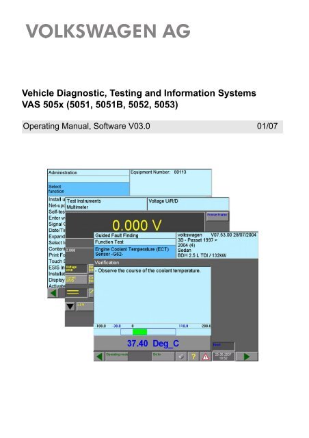
<strong>Vehicle</strong> <strong>Diagnostic</strong>, <strong>Testing</strong> <strong>and</strong> <strong>Information</strong> <strong>Systems</strong><br />
VAS 505x (5051, 5051B, 5052, 5053)<br />
Operating Manual, Software V03.0 01/07
VAS 5051<br />
VAS 5051B<br />
VAS 5052<br />
VAS 5053<br />
Contents<br />
Contents<br />
Safety Instructions ............................................................................................................i<br />
IMPORTANT SAFETY INSTRUCTIONS ........................................................................ ii<br />
1 General <strong>Information</strong> ...........................................................................................1-1<br />
1.1 General Notes ..................................................................................................1-1<br />
1.2 Safety instructions ............................................................................................1-2<br />
1.3 Differences within the tester series ..................................................................1-2<br />
1.3.1 Operating modes ................................................................................1-2<br />
1.3.2 Testers with <strong>and</strong> without Test Instruments .........................................1-3<br />
1.3.3 VAS 5053: administration via partner application ...............................1-3<br />
1.4 Other applicable documents ............................................................................1-3<br />
2 Initial startup .......................................................................................................2-1<br />
2.1 Enter workshop code .......................................................................................2-2<br />
2.1.1 Equipment number ..............................................................................2-3<br />
2.1.2 Importer number <strong>and</strong> dealership number ............................................2-3<br />
2.1.3 Dealership identifier ............................................................................2-5<br />
2.2 Changing the dealership identifier ...................................................................2-6<br />
2.3 Date/Time ........................................................................................................2-6<br />
2.3.1 Setting the date ...................................................................................2-7<br />
2.3.2 Setting the time ...................................................................................2-7<br />
2.3.3 Accepting the date/time ......................................................................2-8<br />
2.4 Back to the start screen ...................................................................................2-9<br />
2.5 Installing br<strong>and</strong> data from CDs ......................................................................2-10<br />
2.6 Installation of additional applications .............................................................2-11<br />
2.7 Printer ............................................................................................................2-12<br />
3 Operation of the masks ......................................................................................3-1<br />
3.1 Masks ...............................................................................................................3-2<br />
3.2 Buttons .............................................................................................................3-2<br />
3.3 Work window ....................................................................................................3-2<br />
3.3.1 Left <strong>and</strong> right information window .......................................................3-3<br />
3.3.2 Dialog box ...........................................................................................3-5<br />
Operating Manual VAS 505x Software V03.0 01/07<br />
A5E00330054/030<br />
All rights reserved.<br />
I
VAS 5051<br />
VAS 5051B<br />
VAS 5052<br />
VAS 5053<br />
Contents<br />
3.3.3 Selection bar .......................................................................................3-6<br />
3.3.4 Scroll bar .............................................................................................3-6<br />
3.3.5 Cursor .................................................................................................3-7<br />
3.3.6 Navigation bar .....................................................................................3-8<br />
3.3.7 Slide controls ....................................................................................3-10<br />
3.3.8 Using the virtual keyboards ...............................................................3-10<br />
3.3.8.1 Alphanumeric keyboard ................................................................3-11<br />
3.3.8.2 Numeric keyboard .........................................................................3-13<br />
3.3.8.3 Decimal keyboard .........................................................................3-14<br />
3.3.8.4 Hexadecimal keyboard .................................................................3-15<br />
3.3.8.5 Virtual keyboard for applications / installations .............................3-16<br />
3.4 USB keyboard <strong>and</strong> mouse .............................................................................3-17<br />
3.4.1 USB keyboard ...................................................................................3-17<br />
3.4.2 USB mouse .......................................................................................3-17<br />
3.5 Print ................................................................................................................3-18<br />
3.5.1 "Print/Save" dialog box .....................................................................3-19<br />
4 <strong>Vehicle</strong> Self-Diagnosis/<strong>OBD</strong> ..............................................................................4-1<br />
5 Test Instruments .................................................................................................5-1<br />
5.1 Overview ..........................................................................................................5-1<br />
5.1.1 Printing measured values ...................................................................5-1<br />
5.2 Starting the Test Instruments ...........................................................................5-2<br />
5.3 Multimeter ........................................................................................................5-3<br />
5.3.1 Direct <strong>and</strong> Alternating Voltage Measurement .....................................5-5<br />
5.3.2 Direct <strong>and</strong> alternating current measurement in-line ............................5-7<br />
5.3.3 Direct <strong>and</strong> Alternating Current Measurement via Current Pick-up ......5-8<br />
5.3.4 Resistance Measurement ...................................................................5-9<br />
5.3.5 Continuity Test ..................................................................................5-10<br />
5.3.6 Diode Test .........................................................................................5-12<br />
5.3.7 Voltage DSO1 ...................................................................................5-14<br />
5.3.8 Pressure T/D .....................................................................................5-15<br />
5.3.9 Temperature T/D ...............................................................................5-16<br />
5.3.10 Calibrate ............................................................................................5-17<br />
5.4 Digital Storage Oscilloscope (DSO) ...............................................................5-18<br />
Operating Manual VAS 505x Software V03.0 01/07<br />
A5E00330054/030<br />
All rights reserved.<br />
II
VAS 5051<br />
VAS 5051B<br />
VAS 5052<br />
VAS 5053<br />
Contents<br />
5.4.1 Channel A, Channel B ......................................................................5-20<br />
5.4.2 Measuring mode ...............................................................................5-25<br />
5.4.3 Trigger Mode .....................................................................................5-27<br />
5.4.4 B<strong>and</strong>width limiting (VAS 5051B only) ...............................................5-30<br />
5.4.5 Freeze Frame ...................................................................................5-30<br />
5.4.5.1 Freeze frame with one measurement cursor displayed ................5-31<br />
5.4.5.2 Freeze frame with measurement cursor 1<br />
<strong>and</strong> measurement cursor 2 displayed ...........................................5-32<br />
5.4.6 Long-term measurement in draw mode ............................................5-34<br />
5.4.7 Tips <strong>and</strong> <strong>Information</strong> .........................................................................5-38<br />
5.5 Parallel mode with Test Instruments <strong>and</strong> <strong>Vehicle</strong> Self-Diagnosis ..................5-40<br />
5.5.1 Overview ...........................................................................................5-40<br />
5.5.2 Operation ..........................................................................................5-41<br />
5.5.3 Values of "Final control diagnosis" diagnostic function .....................5-43<br />
5.5.4 Values of the "Read measured values block" <strong>and</strong> "Basic settings" diagnostic<br />
functions ..................................................................................5-44<br />
5.5.5 Values of "<strong>OBD</strong>" operating mode ......................................................5-44<br />
6 Guided Fault Finding ..........................................................................................6-1<br />
6.1 Overview ..........................................................................................................6-1<br />
6.2 Start Guided Fault Finding ...............................................................................6-7<br />
6.3 "Go to" destination menu .................................................................................6-8<br />
6.4 <strong>Vehicle</strong> identification ........................................................................................6-9<br />
6.4.1 <strong>Vehicle</strong> without CAN diagnostics ......................................................6-10<br />
6.4.2 <strong>Vehicle</strong> with gateway <strong>and</strong> CAN diagnostics ......................................6-10<br />
6.4.2.1 Gateway not registered .................................................................6-11<br />
6.4.2.2 No communication with gateway ..................................................6-12<br />
6.5 Confirming vehicle identification, diagnostic connection ................................6-13<br />
6.6 <strong>Vehicle</strong> system test ........................................................................................6-15<br />
6.6.1 Possible problems .............................................................................6-16<br />
6.6.1.1 <strong>Diagnostic</strong> bus faulty .....................................................................6-16<br />
6.6.1.2 Definitely installed control unit not recognised ..............................6-17<br />
6.6.1.3 Optionally installed control unit not recognised ............................6-17<br />
6.6.2 Observe vehicle system test .............................................................6-18<br />
6.6.3 Start module ......................................................................................6-19<br />
Operating Manual VAS 505x Software V03.0 01/07<br />
A5E00330054/030<br />
All rights reserved.<br />
III
VAS 5051<br />
VAS 5051B<br />
VAS 5052<br />
VAS 5053<br />
Contents<br />
6.7 Fault memory contents ..................................................................................6-20<br />
6.8 Complaint report ............................................................................................6-25<br />
6.9 Function/Component selection ......................................................................6-30<br />
6.9.1 Documents ........................................................................................6-34<br />
6.10 Test plan ........................................................................................................6-36<br />
6.11 Function test ..................................................................................................6-39<br />
6.11.1 Test dialogs .......................................................................................6-43<br />
6.11.2 Measuring instruction (multimeter) ....................................................6-43<br />
6.11.3 Measuring instruction for vehicle systems ........................................6-45<br />
6.11.3.1 Measuring instruction results in a message ..................................6-45<br />
6.11.3.2 Measuring instruction with direct output .......................................6-46<br />
6.11.3.3 Measured values table ..................................................................6-46<br />
6.11.4 Digital Storage Oscilloscope (DSO) measuring instruction ...............6-49<br />
6.11.5 Cancel function test ..........................................................................6-49<br />
6.12 Leaving the Guided Fault Finding application ................................................6-50<br />
6.12.1 Interrupt .............................................................................................6-51<br />
6.12.1.1 Interrupt work briefly (pause) ........................................................6-51<br />
6.12.1.2 "Interrupt" work for a longer period (save job) ..............................6-52<br />
6.12.1.3 Load diagnosis job ........................................................................6-53<br />
6.12.2 Cancel ...............................................................................................6-55<br />
6.12.3 Exit ....................................................................................................6-55<br />
6.13 Diagnosis log .................................................................................................6-57<br />
6.14 Function test log .............................................................................................6-58<br />
6.15 Stop modul .....................................................................................................6-58<br />
6.16 On-line feedback log ......................................................................................6-59<br />
7 Guided Functions ...............................................................................................7-1<br />
7.1 Overview ..........................................................................................................7-1<br />
7.2 Guided Functions run sequence ......................................................................7-5<br />
8 Applications ........................................................................................................8-1<br />
8.1 Overview ..........................................................................................................8-1<br />
8.2 Starting application ..........................................................................................8-1<br />
8.2.1 Starting application from CD-ROM .....................................................8-3<br />
8.2.2 Service training ...................................................................................8-3<br />
Operating Manual VAS 505x Software V03.0 01/07<br />
A5E00330054/030<br />
All rights reserved.<br />
IV
VAS 5051<br />
VAS 5051B<br />
VAS 5052<br />
VAS 5053<br />
Contents<br />
9 Administration ....................................................................................................9-1<br />
9.1 Overview ..........................................................................................................9-1<br />
9.2 Starting Administration .....................................................................................9-3<br />
9.3 Selecting function .............................................................................................9-4<br />
9.4 Install update ....................................................................................................9-5<br />
9.4.1 Base CD ..............................................................................................9-6<br />
9.4.1.1 Loading a base CD .........................................................................9-7<br />
9.4.2 Update base CD .................................................................................9-7<br />
9.4.2.1 Loading an update base CD ...........................................................9-7<br />
9.4.3 Br<strong>and</strong> CD ............................................................................................9-8<br />
9.4.4 Flash CD .............................................................................................9-8<br />
9.5 Net-update .......................................................................................................9-9<br />
9.6 Self-test ..........................................................................................................9-11<br />
9.6.1 Test Instruments unit (VAS 5051 / VAS 5051B only) ........................9-12<br />
9.6.2 <strong>Diagnostic</strong> bus unit ............................................................................9-12<br />
9.7 Enter Workshop Code/Change Dealership Identifier .....................................9-14<br />
9.8 Signal Generator ............................................................................................9-15<br />
9.9 Date/Time ......................................................................................................9-16<br />
9.10 Exp<strong>and</strong>ed Functions ......................................................................................9-16<br />
9.11 Select Initial Graphic ......................................................................................9-16<br />
9.12 Contents .........................................................................................................9-16<br />
9.13 Print Format ...................................................................................................9-17<br />
9.13.1 Printer driver / Paper format ..............................................................9-17<br />
9.13.2 Print type ...........................................................................................9-18<br />
9.13.3 Changing printer properties ..............................................................9-18<br />
9.14 Print jobs (VAS 5053) ....................................................................................9-19<br />
9.15 Touch Screen Calibration ..............................................................................9-20<br />
9.16 ESIS Installation or Update ............................................................................9-22<br />
9.17 Installation or update assist (not VAS 5051) ..................................................9-22<br />
9.18 Display user documentation ...........................................................................9-23<br />
9.18.1 Displaying a document on the VAS 5051 .........................................9-24<br />
9.18.1.1 Zoom .............................................................................................9-24<br />
9.18.1.2 Original size ..................................................................................9-25<br />
Operating Manual VAS 505x Software V03.0 01/07<br />
A5E00330054/030<br />
All rights reserved.<br />
V
VAS 5051<br />
VAS 5051B<br />
VAS 5052<br />
VAS 5053<br />
Contents<br />
9.18.1.3 Backward ......................................................................................9-25<br />
9.18.1.4 Forward .........................................................................................9-25<br />
9.18.1.5 Print ..............................................................................................9-25<br />
9.18.1.6 Operating bar ................................................................................9-26<br />
9.18.2 Displaying a document on the VAS 5052, VAS 5051B,<br />
(VAS 5053) ........................................................................................9-27<br />
9.18.3 Viewing <strong>and</strong> printing user documentation on a PC ...........................9-27<br />
9.19 Activate/deactivate telediagnosis ...................................................................9-28<br />
9.19.1 Telediagnostics (waiting) ..................................................................9-28<br />
9.19.2 Telediagnosis (RSIS) ........................................................................9-31<br />
9.20 ELSA installation ............................................................................................9-33<br />
9.21 ELSA administration ......................................................................................9-33<br />
9.22 Application statistic ........................................................................................9-34<br />
9.23 Installation applications ..................................................................................9-35<br />
9.24 Dimension pressure / temperature .................................................................9-35<br />
9.25 Network settings ............................................................................................9-36<br />
9.25.1 Display network settings ...................................................................9-37<br />
9.25.2 Change CentralPartnerNet-password ...............................................9-37<br />
9.25.3 Adjustusting station name .................................................................9-37<br />
9.25.4 Displaying target-URL .......................................................................9-38<br />
9.25.5 Activate/Deactivate online connection via the<br />
Internet (Secure Client) .....................................................................9-39<br />
9.25.6 Proxy settings ...................................................................................9-39<br />
9.25.7 GeKo-test (confidentiality <strong>and</strong> component protection) ......................9-40<br />
9.25.8 Setting ISDN protocol .......................................................................9-40<br />
9.25.9 Installation radio LAN ........................................................................9-41<br />
9.25.10 Online-connection .............................................................................9-41<br />
9.25.11 Importing importer settings ...............................................................9-42<br />
9.25.12 Application tests ...............................................................................9-42<br />
9.25.13 Activating/deactivating network update after restart .........................9-42<br />
9.26 Exporting function test files ............................................................................9-43<br />
9.27 Import function test files .................................................................................9-43<br />
9.28 System expansions ........................................................................................9-44<br />
9.28.1 Add printer ........................................................................................9-44<br />
Operating Manual VAS 505x Software V03.0 01/07<br />
A5E00330054/030<br />
All rights reserved.<br />
VI
VAS 5051<br />
VAS 5051B<br />
VAS 5052<br />
VAS 5053<br />
Contents<br />
9.29 Keyboard assignment ....................................................................................9-45<br />
9.30 Update installation (only VAS 5053) ..............................................................9-45<br />
9.31 Battery service ...............................................................................................9-46<br />
9.32 Display battery charging ................................................................................9-47<br />
9.33 Switching on erWin documents (only VAS 5051B <strong>and</strong> VAS 5052) ................9-48<br />
9.34 Partner application (VAS 5053) .....................................................................9-48<br />
9.35 Configuration of vehicle communication ........................................................9-49<br />
10 Help ....................................................................................................................10-1<br />
10.1 Overview ........................................................................................................10-1<br />
10.2 Starting <strong>and</strong> closing Help ...............................................................................10-1<br />
10.3 Help Overview ................................................................................................10-2<br />
10.4 Help on pressed button ..................................................................................10-4<br />
11 Abbreviations <strong>and</strong> terms .................................................................................11-1<br />
12 Index ..................................................................................................................12-1<br />
Operating Manual VAS 505x Software V03.0 01/07<br />
A5E00330054/030<br />
All rights reserved.<br />
VII
VAS 5051<br />
VAS 5051B<br />
VAS 5052<br />
VAS 5053<br />
Contents<br />
Applicable software versions<br />
This operating manual applies to base CD release V11.00.<br />
Associated documents<br />
In addition to this operating manual that describes the use of the individual ➚operating<br />
modes, the following relevant technical documents may exist for the individual testers:<br />
• /1/ Start-up/unpacking instructions (tester-specific)<br />
with important information about starting up <strong>and</strong> registering the unit.<br />
• /2/ Brief instructions (tester-specific)<br />
Fold-out sheet with information about the tester <strong>and</strong> also brief information about using<br />
it. This printed documentation is a part of a tester package.<br />
• /3/ Operating Manual VAS 505x Hardware (tester-specific)<br />
Description of tester, display <strong>and</strong> control elements, functions of diagnostic <strong>and</strong> measurement<br />
cables, troubleshooting as well as technical data.<br />
• /4/ Start-up/unpacking instructions including partner application VAS 5053<br />
Describes, in addition to /1/, the installation of the partner application <strong>and</strong> also administration<br />
functions for the VAS 5053.<br />
• /5/ Printer manual<br />
The documentation for the printer is included in the printer package (also see the accompanying<br />
data carrier).<br />
• /6/ VAS 505x Service information<br />
contains important information, addresses <strong>and</strong> telephone hotlines in case of malfunction.<br />
• /7/ <strong>Vehicle</strong> self-diagnosis operating manual<br />
Describes the use of the "<strong>Vehicle</strong> self-diagnosis" operating mode.<br />
Reference may be made to these documents in the operating manual as follows.<br />
Example: (See /3/, chapter "Troubleshooting")<br />
Note<br />
The operating manuals are subject to maintenance <strong>and</strong> are delivered with every base<br />
CD, with the exception of /2/ <strong>and</strong> /5/. Check the manuals from time to time to see<br />
whether there are any updates. You can find information on the display of the manuals<br />
in section 9.18.<br />
Operating Manual VAS 505x Software V03.0 01/07<br />
A5E00330054/030<br />
All rights reserved.<br />
VIII
VAS 5051<br />
VAS 5051B<br />
VAS 5052<br />
VAS 5053<br />
Safety Instructions<br />
Safety Instructions<br />
Meaning of symbols<br />
The safety instructions in the operating manuals, the Startup/Unpacking Instructions or in<br />
other documentation provided, on screen displays on the tester during operation <strong>and</strong> on<br />
the products themselves use symbols with the following meanings:<br />
Warning!<br />
Text with this symbol contains information for your safety <strong>and</strong> how you can reduce the<br />
risk of severe or fatal injury.<br />
The WARNING<br />
symbol warrants particular attention for your safety.<br />
Caution!<br />
Text with this symbol contains information about how you can avoid damage to the<br />
vehicle <strong>and</strong> the tester.<br />
The Caution symbol tells you that if the information is ignored, damage to the<br />
vehicle <strong>and</strong>/or the tester could result (e.g.: Ensure that the touch screen is not touched<br />
with sharp, edged objects.).<br />
Note<br />
Text with this symbol contains additional, useful information.<br />
A Note<br />
information.<br />
symbol contains other, special instructions for using the device, <strong>and</strong> related<br />
Note on further safety instructions<br />
The general safety instructions, which are valid for the complete VAS 505x family of<br />
testers, are listed in the following. Further safety instructions are to be found in the<br />
operating manuals. Therefore, please read the operating manuals before use.<br />
Safety instructions may also appear on the screen of the tester. Follow all the<br />
instructions displayed.<br />
Operating Manual VAS 505x Software V03.0 01/07<br />
A5E00330054/030<br />
All rights reserved.<br />
i
VAS 5051<br />
VAS 5051B<br />
VAS 5052<br />
VAS 5053<br />
Safety Instructions<br />
IMPORTANT SAFETY INSTRUCTIONS<br />
1. Warning!<br />
Read all instructions.<br />
2. Warning!<br />
Do not operate equipment with a damaged cord or if the equipment has been damaged<br />
- until it has been examined by a qualified serviceman.<br />
3. Warning!<br />
Do not let cord hang over edge of table, bench or counter, or come in contact with hot<br />
manifolds or moving fan blades.<br />
4. Warning!<br />
An extension cord is not allowed. For testing use only specified cables.<br />
5. Warning!<br />
Always unplug equipment from electrical outlet when not in use. Never yank cord to pull<br />
plug from outlet. Grasp plug <strong>and</strong> pull to disconnect.<br />
6. Warning!<br />
To protect against risk of fire, do not operate equipment in the vicinity of open<br />
containers of fuel (gasoline).<br />
Operating Manual VAS 505x Software V03.0 01/07<br />
A5E00330054/030<br />
All rights reserved.<br />
ii
VAS 5051<br />
VAS 5051B<br />
VAS 5052<br />
VAS 5053<br />
Safety Instructions<br />
7. Warning!<br />
Adequate ventilation should be provided when working on operating combustion<br />
engines.<br />
8. Warning!<br />
Use only as described in this manual. Use only manufactures’s recommended<br />
attachments.<br />
9. Warning!<br />
Risk of explosions<br />
The devices have internal parts which emit sparks <strong>and</strong> therefore must not be exposed<br />
to flammable fumes. The device should be operated at least 460 mm (18 inches) above<br />
the floor surface since fumes from fuels <strong>and</strong> other materials accumulate at floor level.<br />
10. Warning!<br />
All measurement cables may only be used within the measurement ranges stipulated in<br />
the technical specifications <strong>and</strong> the descriptions in the operating manual. All<br />
measurement pick-ups may only be used on cable whose casing is undamaged. Do not<br />
carry out measurements on damaged cables.<br />
11. Warning!<br />
The devices connected to electrical power supply correspond to protection class 1 <strong>and</strong><br />
are fitted with a safety-tested mains cable. They may only be connected to electrical<br />
networks with an earthed protective conductor (TN networks) or electrical outlets with<br />
earthed protective conductors.<br />
12. Warning!<br />
Fluctuations <strong>and</strong> deviations in the power supply beyond the permitted range of<br />
tolerance can lead to malfunctions <strong>and</strong> damage.<br />
Operating Manual VAS 505x Software V03.0 01/07<br />
A5E00330054/030<br />
All rights reserved.<br />
iii
VAS 5051<br />
VAS 5051B<br />
VAS 5052<br />
VAS 5053<br />
Safety Instructions<br />
13. Warning!<br />
During test drives, secure the tester with a strap on the vehicle's back seat <strong>and</strong> connect<br />
it to the vehicle using the diagnostic cable. A second person must operate the tester<br />
from the back seat. Operation from the front seat is too dangerous, e.g. in the event of<br />
airbag activation.<br />
Only for VAS 5051:<br />
To supply the VAS 5051 with power from the vehicle battery, use only the 3 m diagnostic<br />
cable.<br />
14. Warning!<br />
Electrical ignition systems carry voltages of up to approx. 30 kV. Observe general safety<br />
guidelines for workshops at all times.<br />
15. Warning!<br />
If you open the tester or its accessories without authorisation or carry out improper<br />
alterations to them, considerable risk to you <strong>and</strong> to the device may result.<br />
16. Caution! VAS 5051 - changing fuse<br />
For inline current measurements with the VAS 5051, only a replacement fuse of the<br />
same type <strong>and</strong> same amperage may be installed in order to avoid risks of fire <strong>and</strong> to<br />
protect the device. To order original parts, refer to the corresponding chapters of the<br />
operating manual.<br />
17. Caution! VAS 5051B workshop trolley - ventilation<br />
When operating with the VAS 5051B workshop trolley, make sure that there is sufficient<br />
ventilation for the table power adapter of the tester <strong>and</strong> for the printer. Please note that<br />
even when the tester is switched off, the battery charging circuit remains in operation<br />
<strong>and</strong> the printer is online (although in energy saving mode).<br />
• Completely open the top cover above the printer or the roll-up door during operation<br />
(depending on the existing workshop trolley).<br />
• Heat-dissipation of the table power adapter must not be impaired by objects on top<br />
of it (cable, cloth, etc.).<br />
• Pull the mains cable of the workshop trolley to switch off the complete device.<br />
Operating Manual VAS 505x Software V03.0 01/07<br />
A5E00330054/030<br />
All rights reserved.<br />
iv
VAS 5051<br />
VAS 5051B<br />
VAS 5052<br />
VAS 5053<br />
Safety Instructions<br />
18. Caution! when connecting non-VW vehicles<br />
The VAS 505x diagnostic devices were developed for vehicles from the Volkswagen<br />
group. If the tester is connected directly to vehicles from other manufacturers, damage<br />
to the vehicle could result.<br />
Therefore if non-VW vehicles are to be tested using the general <strong>OBD</strong> functions in the<br />
<strong>Vehicle</strong> Self-Diagnosis application, the <strong>OBD</strong> adapter cable VAS 5052/16 needs to be<br />
connected between the diagnostic cable <strong>and</strong> the diagnostic connection on the vehicle<br />
(with fewer cable connections).<br />
19. Caution! when h<strong>and</strong>ling the battery<br />
• The battery may only be replaced by trained personnel.<br />
• Never short-circuit the battery.<br />
• Never throw the battery into a fire.<br />
• Dispose of or recycle the battery in accordance to the local regulations.<br />
SAVE THESE INSTRUCTIONS!<br />
Release: 2005-03-30<br />
Operating Manual VAS 505x Software V03.0 01/07<br />
A5E00330054/030<br />
All rights reserved.<br />
v
VAS 5051<br />
VAS 5051<br />
VAS 5051B<br />
VAS 5051B<br />
VAS 5052<br />
VAS 5053<br />
VAS 50 53<br />
VAS 5052<br />
General <strong>Information</strong><br />
1 General <strong>Information</strong><br />
1.1 General Notes<br />
The operating manual software contains the information you will need to operate the<br />
tester series VAS 505x, as far as use of the ➚operating modes 1 via the touch screen is<br />
concerned.<br />
All information about the tester/hardware can be be found in /3/.<br />
This documentation is intended to be used by technically qualified persons with the relevant<br />
knowledge in the field of vehicle diagnosis <strong>and</strong> test instruments.<br />
For reasons of clarity the operating manual does not include all details of all versions of<br />
the operating modes described. In the same way the contents of the ➚masks shown<br />
here may differ to a minor extent from the masks shown by the different tester types.<br />
Tester-specific differences are indicated by text <strong>and</strong> / or symbols. The model designation<br />
"VAS 505x" st<strong>and</strong>s for VAS 5051, VAS 5051B, VAS 5052 <strong>and</strong> VAS 5053.<br />
The symbols of the corresponding testers appear at the top of pages containing information<br />
valid for several models.<br />
Table 1-1<br />
Tester symbols<br />
VAS 5051 VAS 5052<br />
VAS 5051B VAS 5053<br />
1. The glossary arrow ➚ indicates that the term so marked is explained in chapter 11.<br />
Operating Manual VAS 505x Software V03.0 01/07<br />
A5E00330054/030<br />
All rights reserved.<br />
1-1
VAS 5051<br />
VAS 5051B<br />
VAS 5052<br />
VAS 5053<br />
General <strong>Information</strong><br />
1.2 Safety instructions<br />
You should comply with all safety instructions. These will be found after the table of contents<br />
<strong>and</strong> at the various relevant places in the operating manual.<br />
1.3 Differences within the tester series<br />
1.3.1 Operating modes<br />
The following table provides an overview of operating modes available in the different<br />
testers.<br />
Table 1-2<br />
VAS 505x Operating modes<br />
Operating mode<br />
VAS<br />
5051 1<br />
VAS<br />
5051B<br />
VAS<br />
5052<br />
VAS<br />
5053<br />
Administration ● ● ● ◗<br />
<strong>Vehicle</strong> Self-Diagnosis ● ● ● ●<br />
<strong>OBD</strong> ● ● ● ●<br />
Test Instruments ● ● ❍ ❍<br />
Guided Fault Finding ● ● ● ❍<br />
Guided Functions ● ● ● ●<br />
Applications ● ● ● ❍<br />
1. For the VAS 5051, there is no communication with LT3 <strong>and</strong> ⁄UDS control units at<br />
present.<br />
●<br />
◗<br />
available, ❍ not available<br />
available in part at the tester, in part via the ➚partner application<br />
Communication with LT3 commercial vehicles <strong>and</strong> UDS control units<br />
Communication with LT3 vehicles is available as a new feature from base CD V10.00<br />
<strong>and</strong> with UDS control units from base CD V11.00.<br />
Operating Manual VAS 505x Software V03.0 01/07<br />
A5E00330054/030<br />
All rights reserved.<br />
1-2
VAS 5051<br />
VAS 5051B<br />
VAS 5052<br />
VAS 5053<br />
General <strong>Information</strong><br />
1.3.2 Testers with <strong>and</strong> without Test Instruments<br />
Within the tester series there are models with <strong>and</strong> without Test Instruments. For the correct<br />
use of the function tests with test instruments available in the Guided Fault Finding,<br />
so-called "replacement values" (see section 6.11) must be input via a ➚virtual keyboard<br />
in the case of testers without Test Instruments. The measurements are carried out using<br />
an external test instrument <strong>and</strong> the measured values then input via the touch screen.<br />
1.3.3 VAS 5053: administration via partner application<br />
Instead of a hard disc, the VAS 5053 is equipped with a flash (memory) card. It does not<br />
have a DVD drive either. This means that some Administration functions cannot be carried<br />
out on the VAS 5053 directly. They are therefore 'boarded out' <strong>and</strong> executed from a partner<br />
application (see /4/). The communication between the partner (VAS 5051B, VAS 5052<br />
or workshop PC) <strong>and</strong> the VAS 5053 is carried out via a USB connection.<br />
1.4 Other applicable documents<br />
Associated documents are listed after the table of contents. Please note that each tester<br />
has its own hardware description. The software description, on the other h<strong>and</strong>, since it<br />
nearly applies to the entire VAS 505x tester series, is provided in a common operating<br />
manual.<br />
Using the operating manuals<br />
The operating manuals are located on the ➚base CD <strong>and</strong> are loaded onto the tester via<br />
the CD. You can also view <strong>and</strong> print the operating manual if you insert the base CD into<br />
the CD/DVD drive of a PC. For more detailed information, see section 9.18.<br />
Caution!<br />
Only insert the base CD in a PC that has already been switched on, <strong>and</strong> remove it from<br />
the CD/DVD drive again without delay after you have viewed the operating manual.<br />
Since the base CD can be booted, the operating system on your PC's hard drive can be<br />
destroyed if the base CD is still in the drive the next time the PC is switched on.<br />
Operating Manual VAS 505x Software V03.0 01/07<br />
A5E00330054/030<br />
All rights reserved.<br />
1-3
VAS 5051<br />
VAS 5051B<br />
VAS 5052<br />
VAS 5053<br />
Initial startup<br />
2 Initial startup<br />
Once the tester has completed the start-up routine, initially a warning will be displayed:<br />
No network communication is possible with the current station name!<br />
Use the menu item Administration / Network settings to change the station name.<br />
This message will appear at every start-up until you change the station name. For information<br />
on how to define this setting, see section 9.25.3.<br />
Click on OK to close this dialog box.<br />
Another dialog box now appears. It appears each time the tester is started. It explains<br />
the meaning of the symbols used for warnings <strong>and</strong> notes. After reading the information,<br />
close the dialog box with OK. You can access the global warnings <strong>and</strong> notes at any time<br />
by clicking on the button with the red warning triangle (see fig. 2-1).<br />
Depending on the tester battery's state of charge on the VAS 5051B <strong>and</strong> VAS 5053, a<br />
prompt may appear asking you to start a battery service cycle. For more information, see<br />
section 9.31.<br />
Closing the dialog boxes enables the start mask. It contains the initial graphic, the<br />
current software version of the base CD <strong>and</strong> the buttons ➚Administration, Warning <strong>and</strong><br />
notes, Help <strong>and</strong> Print. The image you see may vary depending on the software version.<br />
For information on using the buttons, see chapter 3.<br />
<strong>Information</strong> on the<br />
currently loaded base<br />
CD is shown here<br />
Press this button to<br />
open Administration.<br />
Fig. 2-1<br />
Start mask as it appears during initial startup<br />
Printouts, help,<br />
warnings <strong>and</strong> notes,<br />
indication of date <strong>and</strong><br />
time<br />
Operating Manual VAS 505x Software V03.0 01/07<br />
A5E00330054/030<br />
All rights reserved.<br />
2-1
VAS 5051<br />
VAS 5051B<br />
VAS 5052<br />
VAS 5053<br />
Initial startup<br />
2.1 Enter workshop code<br />
Before you can use the tester in your workshop, you must first enter your workshop<br />
code. To do this, you can use the Enter Workshop Code function. This function only<br />
appears when you start the device for the first time.<br />
To enable worldwide equipment identification <strong>and</strong> a unique user assignment, three elements<br />
are used:<br />
• Equipment number<br />
• VZ / importer number 1<br />
• Dealership number<br />
The VZ / importer number <strong>and</strong> dealership number (provided by Volkswagen) must be<br />
input by the user at initial start-up. To do so, first click on the Administration button <strong>and</strong><br />
then select the line "Enter workshop code".<br />
Entered by<br />
manufacturer<br />
Select this<br />
function!<br />
Fig. 2-2<br />
Mask Administration, select function<br />
1. VZ: Sales centre in Germany<br />
Operating Manual VAS 505x Software V03.0 01/07<br />
A5E00330054/030<br />
All rights reserved.<br />
2-2
VAS 5051<br />
VAS 5051B<br />
VAS 5052<br />
VAS 5053<br />
Initial startup<br />
2.1.1 Equipment number<br />
The equipment number (the same as the last five digits of the ser. number on the rating<br />
plate) is held in the read-only memory in the unit <strong>and</strong> cannot be changed by the user<br />
(see fig. 2-2).<br />
Table 2-1<br />
Equipment numbers<br />
Range of<br />
numbers<br />
Model<br />
1 - 19999 VAS 5051<br />
20001 - 49999 VAS 5053<br />
50001 - 79999 VAS 5052<br />
80001 - 99999 VAS 5051B<br />
2.1.2 Importer number <strong>and</strong> dealership number<br />
Two entry masks will appear so that you can enter the workshop code (importer number<br />
<strong>and</strong> dealership number). These masks will only appear once. Another mask will then<br />
appear, allowing you to enter the dealership identifier as shown in table 2-2. You can<br />
change this entry at any time.<br />
Table 2-2<br />
Workshop code<br />
Parameter<br />
Importer number<br />
Dealership number<br />
Dealership identifier<br />
Type of input<br />
three digits from 0 to 9 (number is provided by VW)<br />
five digits from 0 to 9 (number is provided by VW)<br />
you can enter up to two lines, each containing a maximum<br />
of 60 numbers <strong>and</strong> letters, for the name <strong>and</strong><br />
address of your workshop; entries must be in Latin letters<br />
with no diacritical marks<br />
Operating Manual VAS 505x Software V03.0 01/07<br />
A5E00330054/030<br />
All rights reserved.<br />
2-3
VAS 5051<br />
VAS 5051B<br />
VAS 5052<br />
VAS 5053<br />
Initial startup<br />
Corrections:<br />
press C to delete the<br />
rightmost digit in the<br />
display.<br />
Enter your 3-digit<br />
importer number<br />
<strong>and</strong> confirm by<br />
pressing Q.<br />
Fig. 2-3<br />
Mask "Enter importer number"<br />
For information on using the ➚virtual keyboards, see also section 3.3.8.<br />
Enter your 5-digit<br />
dealership number<br />
<strong>and</strong> confirm by<br />
pressing Q.<br />
Fig. 2-4<br />
Mask "Enter Dealership Number"<br />
The workshop code that has been entered remains unchanged even after installing a<br />
new ➚base CD (see section 9.4) <strong>and</strong> once entered can never be changed.<br />
Operating Manual VAS 505x Software V03.0 01/07<br />
A5E00330054/030<br />
All rights reserved.<br />
2-4
VAS 5051<br />
VAS 5051B<br />
VAS 5052<br />
VAS 5053<br />
Initial startup<br />
Make sure that the<br />
entries you have made<br />
are correct. Select<br />
Cancel to enter the<br />
information again.<br />
Note:<br />
It is not possible to<br />
change a workshop<br />
code after it has been<br />
entered!<br />
Fig. 2-5<br />
"Confirmation of input for importer number <strong>and</strong> dealership number" mask<br />
2.1.3 Dealership identifier<br />
After you have confirmed the entries for the importer number <strong>and</strong> dealership number, a<br />
mask will appear so that you can enter the dealership identifier.<br />
Fig. 2-6<br />
Keyboard used for entering dealership identifier<br />
Operating Manual VAS 505x Software V03.0 01/07<br />
A5E00330054/030<br />
All rights reserved.<br />
2-5
VAS 5051<br />
VAS 5051B<br />
VAS 5052<br />
VAS 5053<br />
Initial startup<br />
Enter your dealership identifier (such as company name <strong>and</strong> address) here line by line.<br />
Conclude the input of each line using the white "Q" button (not with the grey letter buttons).<br />
Use the white arrow button to switch between lower <strong>and</strong> upper case letters. The<br />
other arrow keys may be used for changing the input position.<br />
For more information on using the virtual keyboard, see section 3.3.8.<br />
2.2 Changing the dealership identifier<br />
After you have entered the workshop code, the function "Enter workshop code" is<br />
replaced by "Change dealership identifier". With this function, you can change your<br />
dealership identifier at any time.<br />
2.3 Date/Time<br />
After entering the workshop code, you can change to Administration operating mode to<br />
set the correct date <strong>and</strong> time for the system. Select "Date/time" in the list to display the<br />
following mask:<br />
The arrows appear<br />
after touching a button.<br />
Fig. 2-7<br />
Mask "Date/Time", set hour<br />
Once the date/time has been set, it can only be overwritten again under specific circumstances<br />
(see section 2.3.3).<br />
Operating Manual VAS 505x Software V03.0 01/07<br />
A5E00330054/030<br />
All rights reserved.<br />
2-6
VAS 5051<br />
VAS 5051B<br />
VAS 5052<br />
VAS 5053<br />
Initial startup<br />
2.3.1 Setting the date<br />
The date is displayed according to the German st<strong>and</strong>ard: day - month - year. To change<br />
the date, select the display field for the day, the month or the year. The appropriate value<br />
can be set individually using the two arrow keys to the left <strong>and</strong> right of the date display.<br />
The left-h<strong>and</strong> knob decrements the selection by one unit.<br />
The right-h<strong>and</strong> knob increments the selection by one unit.<br />
2.3.2 Setting the time<br />
To change the time, select the display field for the hour or the minute. The appropriate<br />
value can be set individually using the two arrow keys to the left <strong>and</strong> right of the time<br />
display.<br />
The left-h<strong>and</strong> knob decrements the selection by one unit.<br />
The right-h<strong>and</strong> knob increments the selection by one unit.<br />
Operating Manual VAS 505x Software V03.0 01/07<br />
A5E00330054/030<br />
All rights reserved.<br />
2-7
VAS 5051<br />
VAS 5051B<br />
VAS 5052<br />
VAS 5053<br />
Initial startup<br />
2.3.3 Accepting the date/time<br />
Note<br />
A set date/time is stored on the tester <strong>and</strong> updated continuously from this point forward.<br />
Values before the date last saved are not accepted. If you attempt to store an older<br />
date, an appropriate message is displayed.<br />
In this case, the date can only be reset after the reinstallation of a formatting base CD<br />
(e.g. Base V07.00.00).<br />
Press "Back" to return to the previous screen mask. The set values<br />
are used as the system date/time. The current time values are<br />
always displayed again on the navigation bar at the bottom of the<br />
work window.<br />
By pressing "Go to", you can "Cancel" or "Exit" the time input <strong>and</strong> exit the mask without<br />
changing the system time.<br />
Operating Manual VAS 505x Software V03.0 01/07<br />
A5E00330054/030<br />
All rights reserved.<br />
2-8
VAS 5051<br />
VAS 5051B<br />
VAS 5052<br />
VAS 5053<br />
Initial startup<br />
2.4 Back to the start screen<br />
With the Go to button <strong>and</strong> subsequent selection of the Exit line you can return to the start<br />
screen from the Administration operating mode.<br />
Now the tester is ready for operation <strong>and</strong> displays e. g. the following start screen with<br />
other activated buttons.<br />
Fig. 2-8<br />
Start mask after entering the dealer data<br />
The current version of the base CD is shown in the start mask. Included in this information<br />
are the language designation, version number <strong>and</strong> version date.<br />
The start screen offers you the following selection:<br />
• ➚<strong>Vehicle</strong> Self-Diagnosis, see /7/<br />
• ➚<strong>OBD</strong>, see /7/<br />
• ➚Test Instruments, see chapter 5 (Replacement value input for VAS 5052)<br />
• ➚Guided Fault Finding, see chapter 6<br />
• ➚Guided Functions, see chapter 7<br />
• ➚Applications, see chapter 8<br />
• ? (Help), see chapter 10<br />
• (safety information), see section 3.3.6<br />
• Print; see section 3.5 <strong>and</strong> the corresponding sections of the operating modes in<br />
question<br />
• ➚Applications; see chapter 8 (not VAS 5053)<br />
Operating Manual VAS 505x Software V03.0 01/07<br />
A5E00330054/030<br />
All rights reserved.<br />
2-9
VAS 5051<br />
VAS 5051B<br />
VAS 5052<br />
VAS 5053<br />
Initial startup<br />
2.5 Installing br<strong>and</strong> data from CDs<br />
For Guided Fault Finding (not with VAS 5053) <strong>and</strong> Guided Functions to work, you must<br />
install one or more ➚br<strong>and</strong> CDs as follows:<br />
1. Open the CD / DVD drive <strong>and</strong> insert the desired br<strong>and</strong> CD. Be sure to read the information<br />
about inserting CDs (see /3/).<br />
2. Close the CD drive.<br />
3. Press Administration.<br />
4. In the mask that appears, choose "CD update/installation" from the menu (fig. 2-9.<br />
For more information about this function, see section 9.4). Confirm the security dialog<br />
that follows.<br />
5. The contents of the br<strong>and</strong> CD are now installed on the VAS 505x. It can take more<br />
than an hour to carry out a full installation. As soon as installation is complete, the tester<br />
switches from Administration operating mode back to the start mask. A br<strong>and</strong> symbol<br />
is displayed in the top right corner of the screen to indicate which br<strong>and</strong> CD(s)<br />
have been installed on the tester.<br />
Fig. 2-9<br />
Installing a br<strong>and</strong> CD<br />
Operating Manual VAS 505x Software V03.0 01/07<br />
A5E00330054/030<br />
All rights reserved.<br />
2-10
VAS 5051<br />
VAS 5051B<br />
VAS 5052<br />
VAS 5053<br />
Initial startup<br />
Two br<strong>and</strong><br />
CDs are<br />
loaded<br />
Fig. 2-10<br />
Start mask with br<strong>and</strong> symbol after installation of br<strong>and</strong> CD<br />
6. Remove the CD from the drive.<br />
Install additional CDs if necessary by repeating steps 1 through 6.<br />
For installation on the VAS 5053 via the ➚partner application, see /4/.<br />
2.6 Installation of additional applications<br />
The installation of additional applications, such as e.g. ELSA, erWin, Bentley-Assist or<br />
ESIS, is described in the administration (see chapter 9).<br />
After the installation, an appropriate button, e.g. "Elsa Win", appears in the start mask,<br />
above the "Applications" button.<br />
Operating Manual VAS 505x Software V03.0 01/07<br />
A5E00330054/030<br />
All rights reserved.<br />
2-11
VAS 5051<br />
VAS 5051B<br />
VAS 5052<br />
VAS 5053<br />
Initial startup<br />
2.7 Printer<br />
Note<br />
For information about printers <strong>and</strong> possible settings, see section 9.13 <strong>and</strong><br />
section 9.28.1.<br />
On/Off switch (VAS 5051/VAS 5051B printer)<br />
If the on/off switch on the left side of the printer is off, switch it to ON. You will see the<br />
message "INITIALIZING" in the display field while it is starting up. Once operationally<br />
ready, the printer switches to display "ON-LINE..." <strong>and</strong> the "Ready" LED next to the display<br />
panel lights up.<br />
The printer can remain on because it switches automatically to st<strong>and</strong>by mode.<br />
Note<br />
When a print job is started, st<strong>and</strong>by mode is automatically canceled <strong>and</strong> the internal<br />
heating element is switched on. When the operating temperature is reached (after<br />
approx. 60 s) printing begins.<br />
Operating Manual VAS 505x Software V03.0 01/07<br />
A5E00330054/030<br />
All rights reserved.<br />
2-12
VAS 5051<br />
VAS 5051B<br />
VAS 5052<br />
VAS 5053<br />
Operation of the masks<br />
3 Operation of the masks<br />
4<br />
4<br />
5<br />
3<br />
6<br />
7<br />
8<br />
2<br />
9<br />
1<br />
Fig. 3-1<br />
Overview – masks<br />
1. ➚Mask (screen display)<br />
2. Button in the navigation bar<br />
3. ➚Work window<br />
4. Left <strong>and</strong> right ➚information window<br />
5. ➚Dialog box<br />
6. ➚Selection bar<br />
7. ➚Scroll bar<br />
8. Cursor<br />
9. ➚Navigation bar<br />
Note<br />
In "<strong>Vehicle</strong> self-diagnosis" operating mode, the use of the masks may differ from this<br />
description. For more information about the operation of the vehicle self-diagnosis,<br />
see /7/.<br />
Operating Manual VAS 505x Software V03.0 01/07<br />
A5E00330054/030<br />
All rights reserved.<br />
3-1
VAS 5051<br />
VAS 5051B<br />
VAS 5052<br />
VAS 5053<br />
Operation of the masks<br />
3.1 Masks<br />
The graphic displays on the screen are known as "masks" (fig. 3-1, 1). They display all<br />
the information <strong>and</strong> control functions.<br />
The masks displayed on the tester are usually structured in the same way: in the bottom<br />
section there is a bar with control elements (the ➚navigation bar), the middle <strong>and</strong> largest<br />
section is taken up by the work window in which you make your selection or can enter values.<br />
The two information windows are above the work window.<br />
3.2 Buttons<br />
In each mask, you will only see the buttons (fig. 3-1, 2) that are necessary for a particular<br />
task. You select the various functions with these buttons. The colour of the button shows<br />
you whether or not it is activated. If the button is dark it is pressed or switched on.<br />
pressed button,<br />
function active<br />
You have selected this button. As soon as<br />
you are no longer touching the screen,<br />
the desired comm<strong>and</strong> is executed.<br />
button not pressed,<br />
function can be activated<br />
You can see this button on the screen but<br />
have not activated it.<br />
3.3 Work window<br />
The work window (fig. 3-1, 3) takes up the largest part of the mask. The display changes<br />
according to the operating mode <strong>and</strong> current progress.<br />
Operating Manual VAS 505x Software V03.0 01/07<br />
A5E00330054/030<br />
All rights reserved.<br />
3-2
VAS 5051<br />
VAS 5051B<br />
VAS 5052<br />
VAS 5053<br />
Operation of the masks<br />
3.3.1 Left <strong>and</strong> right information window<br />
Most of the masks contain two information windows (fig. 3-1, 4) which are located above<br />
the work window.<br />
Note<br />
The contents of the working <strong>and</strong> information windows illustrated in this operating manual<br />
are examples <strong>and</strong> need not necessarily be the same as the contents of your tester.<br />
The left-h<strong>and</strong> information window displays the following information:<br />
• 1st line: Name of the operating mode (<strong>Vehicle</strong> Self-Diagnosis, Applications, Guided<br />
Fault Finding, Guided Functions, Administration).<br />
• 2nd line: Name of the function activated in the respective operating mode<br />
• 3rd <strong>and</strong> 4th line: Operating instructions (e.g.: Select engine code), status (e.g.: Function<br />
not found) or detailed information on the displayed function.<br />
Fig. 3-2<br />
Display in the left-h<strong>and</strong> information window<br />
Operating Manual VAS 505x Software V03.0 01/07<br />
A5E00330054/030<br />
All rights reserved.<br />
3-3
VAS 5051<br />
VAS 5051B<br />
VAS 5052<br />
VAS 5053<br />
Operation of the masks<br />
In the right-h<strong>and</strong> information window, results or the previous selection are displayed.<br />
In Test Instruments operating mode, fault reports are also displayed in this window.<br />
Fig. 3-3<br />
Selection of a complaint report in the right-h<strong>and</strong> information window<br />
Operating Manual VAS 505x Software V03.0 01/07<br />
A5E00330054/030<br />
All rights reserved.<br />
3-4
VAS 5051<br />
VAS 5051B<br />
VAS 5052<br />
VAS 5053<br />
Operation of the masks<br />
3.3.2 Dialog box<br />
A ➚dialog box (fig. 3-1, 5) is a small mask which is displayed over the main mask. It<br />
shows additional information, operating possibilities <strong>and</strong> fault messages to be able to<br />
execute further steps in the selected program.<br />
Note<br />
As long as a dialog box is open, the buttons of the main mask cannot be pressed. You<br />
have to press a button in the dialog box to close it first.<br />
The following buttons may appear in the dialog boxes:<br />
Table 3-1<br />
Buttons of the dialog boxes (selection)<br />
Button<br />
Cancel<br />
Display<br />
Exit<br />
OK<br />
Pause<br />
Close<br />
Overview<br />
Interrupt<br />
Meaning<br />
You abort an action <strong>and</strong> return to the previous mask<br />
Allows you to display image or text documents.<br />
You end an operating mode <strong>and</strong> return to the system start screen<br />
You confirm the action or a dialog with "OK".<br />
Work is interrupted briefly <strong>and</strong> then continued.<br />
The dialog box is closed.<br />
You are shown a selection list where you can select the desired<br />
text or action.<br />
Work is interrupted for an extended period of time, <strong>and</strong> data is<br />
saved.<br />
Printer symbol: Starts a screen printout which sends what you see<br />
on screen to the selected output medium. For more details, see<br />
section 3.5.1.<br />
The help also appears in a dialog box. See chapter 10 for using help.<br />
Operating Manual VAS 505x Software V03.0 01/07<br />
A5E00330054/030<br />
All rights reserved.<br />
3-5
VAS 5051<br />
VAS 5051B<br />
VAS 5052<br />
VAS 5053<br />
Operation of the masks<br />
3.3.3 Selection bar<br />
After selecting a line in the work window or in a dialog box, this line is highlighted by<br />
means of a black selection bar (fig. 3-1, 6). The words in the line you have selected are<br />
shown in white.<br />
After you have made your selection, the next mask will usually appear as soon as you<br />
move your finger away from the touch screen.<br />
If this is not the case, your tester offers you the possibility of selecting several texts. Select<br />
all the texts you want to mark. To then go to the next mask, press the Continue button (see<br />
page 3-8).<br />
3.3.4 Scroll bar<br />
If the complete text cannot be displayed in a dialog box or mask, a scroll bar (fig. 3-1, 7)<br />
appears on the right. It consists of a slide <strong>and</strong> two arrows. The length of the slide shows<br />
you whether it is a large or a small document. The smaller the slide the larger the text<br />
which has not yet been displayed. To read the text, place your finger on the slide <strong>and</strong><br />
move it up or down. (VAS 5052: Alternatively, you can press <strong>and</strong> hold the upper mouse<br />
button <strong>and</strong> move the slide using the navigation button.) The desired text is displayed. You<br />
can, however, also move it line by line. If you touch or click the "Arrow down" ( ) the text<br />
moves up one line, with the "Arrow up" ( ) key it moves down one line.<br />
Operating Manual VAS 505x Software V03.0 01/07<br />
A5E00330054/030<br />
All rights reserved.<br />
3-6
VAS 5051<br />
VAS 5051B<br />
VAS 5052<br />
VAS 5053<br />
Operation of the masks<br />
3.3.5 Cursor<br />
The cursor (fig. 3-1, 8) of the tester takes on various forms depending on its present<br />
function.<br />
Table 3-2<br />
Forms of the cursor<br />
Appearance Function Note<br />
The "arrow" is the cursor form<br />
with which you select functions<br />
or buttons.<br />
Controlled by touching the screen.<br />
On VAS 5052, it is also possible to<br />
use the mouse control.<br />
The "hourglass" appears when<br />
the tester is processing your<br />
inputs.<br />
No further inputs should be made<br />
when the hourglass appears. Wait<br />
until the cursor changes back to an<br />
arrow.<br />
The ”printer” appears when<br />
you have sent a print comm<strong>and</strong><br />
to a connected printer by<br />
pressing the ”Print” button.<br />
No further inputs should be made<br />
when this display appears. Wait until<br />
the cursor changes back to an arrow.<br />
Operating Manual VAS 505x Software V03.0 01/07<br />
A5E00330054/030<br />
All rights reserved.<br />
3-7
VAS 5051<br />
VAS 5051B<br />
VAS 5052<br />
VAS 5053<br />
Operation of the masks<br />
3.3.6 Navigation bar<br />
The navigation bar (fig. 3-1, 9) is at the bottom of the mask. You can call help <strong>and</strong> service<br />
functions with the buttons in this line. The work window changes every time you press a<br />
button. The navigation bar contains a maximum of eight different operating buttons as<br />
well as the indication of the date <strong>and</strong> time. The number of buttons actually available<br />
depends on the type of mask <strong>and</strong> its current state.<br />
Fig. 3-4<br />
Overview of buttons on the navigation bar (example)<br />
After you have pressed the desired button, the tester will carry out the corresponding<br />
action.<br />
If provided, the buttons appearing on the navigation bar have the following functions:<br />
You can abort the current function or return to the previous mask with<br />
the Back button.<br />
Using this button, you can switch from Guided Fault Finding or Guided<br />
Functions to another operating mode.<br />
Use this button to switch directly to another operating mode.<br />
Using this button in Guided Functions, you can go to the mask <strong>Vehicle</strong><br />
system test.<br />
Using this button in Guided Functions, you can start the <strong>Vehicle</strong><br />
system test.<br />
You call the tester help function (see chapter 10).<br />
By pressing this button, you can view general warnings ("Caution",<br />
"Warning") <strong>and</strong> notes.<br />
You go to the next mask with the Continue button.<br />
Operating Manual VAS 505x Software V03.0 01/07<br />
A5E00330054/030<br />
All rights reserved.<br />
3-8
VAS 5051<br />
VAS 5051B<br />
VAS 5052<br />
VAS 5053<br />
Operation of the masks<br />
This button opens the "Go to destination" menu. In the menu, you will<br />
find different items depending on the current operating mode <strong>and</strong><br />
function of the tester.<br />
• Press "Cancel" to go to the first ➚mask of the current operating<br />
mode.<br />
• Press "Exit" to go to the start mask.<br />
• Press "Administration" to go to a limited number of administration<br />
functions. You can also use these functions in other active operating<br />
modes, such as Test Instruments <strong>and</strong> Guided Fault Finding. Afterwards,<br />
press the appropriate button on the navigation bar to<br />
return to the original operating mode. The following functions are<br />
available at present (depending on the tester, see chapter 9 for<br />
function descriptions):<br />
− Change dealership identifier<br />
− Contents<br />
− Print format<br />
− Display user documentation<br />
− Activate telediagnosis<br />
− Network settings<br />
− Configuration of vehicle communication<br />
• If other applications are active in addition to the described operating<br />
modes, you can switch to the applications by selecting the corresponding<br />
name.<br />
• In Guided Fault Finding test stepts can be selected which have already<br />
been carried out. This allows you to go back in the function<br />
test in order to change entries or selections as needed (see<br />
chapter 6.3).<br />
For the print options, see section 3.5.<br />
Operating Manual VAS 505x Software V03.0 01/07<br />
A5E00330054/030<br />
All rights reserved.<br />
3-9
VAS 5051<br />
VAS 5051B<br />
VAS 5052<br />
VAS 5053<br />
Operation of the masks<br />
3.3.7 Slide controls<br />
You can change the setting values continuously with the slide control.<br />
Fig. 3-5<br />
Slide control<br />
Touch the lighter coloured control knob <strong>and</strong> pull it slowly to the right or left depending on<br />
whether you want to set the value higher or lower.<br />
If you touch the area to the right or left of the slide control, the value is incremented or<br />
decremented.<br />
3.3.8 Using the virtual keyboards<br />
The tester does not have a traditional keyboard. If it is necessary to input data, a socalled<br />
➚virtual keyboard will appear on the touch screen, allowing you to enter text by<br />
touching the "keys" on the screen. The layout of the virtual keyboard changes to suit the<br />
application case in question.<br />
A virtual keyboard consists of an input field (which provides various keys) <strong>and</strong> a display<br />
field alongside or above it which displays the text you have input.<br />
The tester uses several types of virtual keyboards for special tasks. Examples are shown<br />
in the following sections.<br />
Note<br />
You can also enter characters using a keyboard connected to the tester. See<br />
section 3.4.1.<br />
Operating Manual VAS 505x Software V03.0 01/07<br />
A5E00330054/030<br />
All rights reserved.<br />
3-10
VAS 5051<br />
VAS 5051B<br />
VAS 5052<br />
VAS 5053<br />
Operation of the masks<br />
3.3.8.1 Alphanumeric keyboard<br />
When the alphanumeric keyboard appears on the screen you can enter letters, numbers<br />
<strong>and</strong> special characters. Your input can be viewed in the field above the keyboard.<br />
To enter a text or string of numbers, touch or click the desired buttons in the right order.<br />
Note<br />
If the text or the sequence of numbers is too long, an acoustic signal is emitted.<br />
Examples of alphanumeric keyboards are shown in fig. 3-6 <strong>and</strong> fig. 3-7. Depending on<br />
the task, different keyboards arrangements are used.<br />
Display field for<br />
entered texts<br />
Fig. 3-6<br />
Alphanumeric keyboard (lowercase letters) with display field<br />
Fig. 3-7<br />
Alphanumeric keyboard (uppercase letters) with display field<br />
Operating Manual VAS 505x Software V03.0 01/07<br />
A5E00330054/030<br />
All rights reserved.<br />
3-11
VAS 5051<br />
VAS 5051B<br />
VAS 5052<br />
VAS 5053<br />
Operation of the masks<br />
Special keys<br />
The alphanumeric keyboard has some special keys (some of which have a lighter background)<br />
with the following functions.<br />
You can use this button to delete <strong>and</strong> correct your input. If you touch or<br />
press C for "Clear" the last entered character is cleared; if you use this<br />
button several times, the text is deleted character by character in reverse<br />
as long as characters still exist.<br />
The Q button means ➚Quit. You usually use this button to confirm <strong>and</strong> terminate<br />
your entry. In multi-line input possibilities, you can use Q to move<br />
to the next line. In the left h<strong>and</strong> information window you are shown how<br />
many characters <strong>and</strong> lines you can enter.<br />
This corresponds to a keyboard shift key. When you touch or click it, the<br />
display of the keyboard changes from upper case letters with special characters<br />
to lower case letters with numbers <strong>and</strong> vice versa (see fig. 3-6,<br />
fig. 3-7). This button only appears in the alphanumeric keyboard.<br />
This button is required to insert a space between words or letters.<br />
This key moves the input position up a line.<br />
This key moves the input position back a character.<br />
This key moves the input position forward a character.<br />
This key moves the input position down a line.<br />
Operating Manual VAS 505x Software V03.0 01/07<br />
A5E00330054/030<br />
All rights reserved.<br />
3-12
VAS 5051<br />
VAS 5051B<br />
VAS 5052<br />
VAS 5053<br />
Operation of the masks<br />
3.3.8.2 Numeric keyboard<br />
Enter the desired value by touching the number keys. The numbers you have input will<br />
be displayed in the field at the top.<br />
Fig. 3-8<br />
Numerical keyboard with display field<br />
Special keys<br />
The numerical keyboard includes special keys C <strong>and</strong> Q. They have the same function as<br />
those on the alphanumeric keyboard.<br />
Operating Manual VAS 505x Software V03.0 01/07<br />
A5E00330054/030<br />
All rights reserved.<br />
3-13
VAS 5051<br />
VAS 5051B<br />
VAS 5052<br />
VAS 5053<br />
Operation of the masks<br />
3.3.8.3 Decimal keyboard<br />
Enter the desired value by touching the number keys. The numbers you have input will<br />
be displayed in the field to the left.<br />
Fig. 3-9<br />
Decimal keyboard with display field<br />
Special keys<br />
The decimal keyboard includes special keys C <strong>and</strong> Q <strong>and</strong> the arrow keys. They have the<br />
same function as those on the alphanumeric keyboard. The keyboard also has the following<br />
additional special keys:<br />
This key inserts a positive sign.<br />
This key inserts a negative sign.<br />
This key inserts a decimal point.<br />
Operating Manual VAS 505x Software V03.0 01/07<br />
A5E00330054/030<br />
All rights reserved.<br />
3-14
VAS 5051<br />
VAS 5051B<br />
VAS 5052<br />
VAS 5053<br />
Operation of the masks<br />
3.3.8.4 Hexadecimal keyboard<br />
Enter the desired value by touching the characters. The numbers you have input will be<br />
displayed in the field to the left.<br />
Fig. 3-10<br />
Hexadecimal keyboard with display field<br />
Special keys<br />
The hexadecimal keyboard includes special keys C <strong>and</strong> Q <strong>and</strong> the arrow keys. They have<br />
the same function as those on the alphanumeric keyboard.<br />
Operating Manual VAS 505x Software V03.0 01/07<br />
A5E00330054/030<br />
All rights reserved.<br />
3-15
VAS 5051<br />
VAS 5051B<br />
VAS 5052<br />
VAS 5053<br />
Operation of the masks<br />
3.3.8.5 Virtual keyboard for applications / installations<br />
For operating applications (Elsa Win, erWin, etc.) <strong>and</strong> for installation purposes (ELSA,<br />
printer drivers, etc.), an operating bar appears at bottom right on the screen, with five<br />
rectangular operating buttons <strong>and</strong> a selection list. You can use the first four buttons to<br />
activate a virtual alphanumeric keyboard, which will appear in the corner of the screen<br />
corresponding to the symbol shown on the button you press. This virtual keyboard is language-specific<br />
<strong>and</strong> can be set via the "Keyboard assignment" function (section 9.29) in<br />
Administration.<br />
When you press the fifth button, the virtual keyboard will disappear again <strong>and</strong> the operating<br />
bar shifted to the corner last selected.<br />
You can use the menu bar that appears in order to return to other applications that have<br />
been loaded or to the start mask via the "System Start" menu item.<br />
Fig. 3-11<br />
Operating bar of the virtual keyboard<br />
Fig. 3-12<br />
Example with GB keyboard assignment<br />
The virtual keyboard is copyright of the manufacturer:<br />
© 2000 MontFocus <strong>Information</strong> <strong>Systems</strong> Ltd. All rights reserved.<br />
Operating Manual VAS 505x Software V03.0 01/07<br />
A5E00330054/030<br />
All rights reserved.<br />
3-16
VAS 5051<br />
VAS 5051B<br />
VAS 5052<br />
VAS 5053<br />
Operation of the masks<br />
3.4 USB keyboard <strong>and</strong> mouse<br />
3.4.1 USB keyboard<br />
If a USB keyboard is connected, you can make inputs in applications or during installations.<br />
It is an alternative to the virtual keyboard in section 3.3.8.<br />
A language-specific keyboard is provided. The keyboard can be set via the "Keyboard assignment"<br />
function (section 9.29) in administration.<br />
3.4.2 USB mouse<br />
As an alternative to operating via the touch screen, a connected USB mouse can also be<br />
used with the VAS 5051B.<br />
Operating Manual VAS 505x Software V03.0 01/07<br />
A5E00330054/030<br />
All rights reserved.<br />
3-17
VAS 5051<br />
VAS 5051B<br />
VAS 5052<br />
VAS 5053<br />
Operation of the masks<br />
3.5 Print<br />
If you press the "Print" button on the ➚navigation bar, a sub-menu<br />
provides you with various options for the output of results via a printer/<br />
➚external storage device. Before using a printer, make that it has<br />
been set correctly (see section 9.13).<br />
• Screen: Prints the contents of the screen that is currently visible<br />
(screen shot). This option is always possible.<br />
• Enter vehicle ID no./licence plate no.: In operating modes <strong>Vehicle</strong><br />
Self-Diagnosis, Guided Fault Finding <strong>and</strong> Guided Functions,<br />
you can enter the chassis number <strong>and</strong> licence plate number of the<br />
tested vehicle before issuing the log by using the alphanumeric<br />
keyboard that appears. In this way, the vehicle ID number <strong>and</strong> licence<br />
plate number will appear in the log, allowing clear identification<br />
later on. When logs are saved to removable storage device,<br />
the vehicle ID number also appears in the file name. For this reason,<br />
you must enter the vehicle ID number before saving. This data<br />
is deleted when you quit the operating mode.<br />
• Safely remove hardware (not for VAS 5053)<br />
This menu item is only available if you have used a USB external<br />
storage device to output data. Make sure to select this option prior<br />
to disconnecting the external storage device from the tester, otherwise<br />
the transferred data might be lost. A dialog box informs you<br />
when you may disconnect the external storage device without any<br />
loss of data.<br />
You can find further print functions (diagnosis protocol, ...) in the<br />
appropriate sections of the corresponding operating modes.<br />
On starting a print job (screen, protocol, …) a dialog box appears<br />
so that you are able to specify the job in more detail, see<br />
section 3.5.1.<br />
Note on protocols<br />
In the VAS 505x, protocols are output in XML format together with the corresponding<br />
format file "report.xsl". If data is on a external storage device <strong>and</strong> it is to be displayed on<br />
a PC, an appropriate application for reading the data is required, such as Internet<br />
Explorer 6.0. The format file is only written to the external storage device once, even if<br />
multiple protocols were output. It specifies the format of the pages displayed.<br />
Operating Manual VAS 505x Software V03.0 01/07<br />
A5E00330054/030<br />
All rights reserved.<br />
3-18
VAS 5051<br />
VAS 5051B<br />
VAS 5052<br />
VAS 5053<br />
Operation of the masks<br />
3.5.1 "Print/Save" dialog box<br />
On assigning a print job, a dialog box appears. Its operating buttons depend on the current<br />
situation:<br />
Fig. 3-13<br />
Example of the dialog box for a print job<br />
Use this dialog box to specify the print job in detail. You may enter multiple outputs in<br />
succession, e.g. one for a printer (paper) <strong>and</strong> one for a USB memory.<br />
The dialog box remains open until you press the "Continue" button. The selected print<br />
job is displayed under the title bar. The option of writing to USB memory or diskette is<br />
provided only if the appropriate external storage device has been connected <strong>and</strong> recognised<br />
If the USB memory stick is connected later on <strong>and</strong> recognised by the system, the<br />
dialog box is updated.<br />
If you press the printer symbol on the title bar, another dialog box appears that you can<br />
use to specify the output of the desired screen content.<br />
Functions of the operating buttons:<br />
• Print<br />
Printout via the configured printer (see section 9.13).<br />
• Save to diskette<br />
Output to the disc drive connected.<br />
• Save to USB stick (USB memory)<br />
Output to the USB memory connected. You connect a USB memory later on, the corresponding<br />
button is displayed.<br />
• Send for online technical support<br />
Output to the "ProtoURL" address via LAN connection (display option, see<br />
section 9.25.4). If there is no connection, an appropriate message is displayed <strong>and</strong><br />
the protocol is stored temporarily on the tester (also see section 6.16). You can only<br />
send the diagnostic protocol of the Guided Fault Finding/Guided Functions online.<br />
Operating Manual VAS 505x Software V03.0 01/07<br />
A5E00330054/030<br />
All rights reserved.<br />
3-19
VAS 5051<br />
VAS 5051B<br />
VAS 5052<br />
VAS 5053<br />
Operation of the masks<br />
• Safely remove hardware (not for VAS 5053)<br />
This button appears if a USB memory is connected. Press it before you remove the<br />
USB memory (also see section 3.5).<br />
• Save to VAS 5053 (only for VAS 5053)<br />
If no printer is connected, print jobs may be saved to the VAS 5053 <strong>and</strong> printed at a<br />
later point in time (also see section 9.14).<br />
• Enter vehicle identification no./license plate no.<br />
If the vehicle identification no. <strong>and</strong> the license plate no. are required to output a protocol<br />
(also see section 3.5), these values are requested here if they have not been entered<br />
yet.<br />
If the vehicle identification no. has already been entered or found automatically during<br />
the ➚vehicle system test, then you only need to enter the vehicle license number. You<br />
do not need to repeat this. After such a data request <strong>and</strong> the corresponding input, you<br />
will need to restart the printout.<br />
• Help<br />
Help for the dialog.<br />
• Continue<br />
Closes the dialog box.<br />
Printing the diagnosis protocol<br />
If a diagnosis protocol is output, you are asked whether you would like a complete protocol<br />
or a short version (see section 6.13; not for "Send for online technical support").<br />
Printing user manuals<br />
Printout is only possible using a printer, the "Print/Save" dialog box does not appear.<br />
However, the desired page range can be entered prior to printing.<br />
Operating Manual VAS 505x Software V03.0 01/07<br />
A5E00330054/030<br />
All rights reserved.<br />
3-20
VAS 5051<br />
VAS 5051B<br />
VAS 5052<br />
VAS 5053<br />
<strong>Vehicle</strong> Self-Diagnosis/<strong>OBD</strong><br />
4 <strong>Vehicle</strong> Self-Diagnosis/<strong>OBD</strong><br />
Note<br />
For information on the use of the "<strong>Vehicle</strong> self-diagnosis" mode, see /7/.<br />
Operating Manual VAS 505x Software V03.0 01/07<br />
A5E00330054/030<br />
All rights reserved.<br />
4-1
VAS 5051<br />
VAS 5051B<br />
Test Instruments<br />
5 Test Instruments<br />
5.1 Overview<br />
The Test Instruments operating mode allows you to set the testing unit with the help of<br />
parameter masks <strong>and</strong> then use the unit to perform tests. Measurement results are displayed<br />
numerically <strong>and</strong>/or graphically on the screen.<br />
Note<br />
There are no special Test Instruments provided for the VAS 5052 <strong>and</strong> the VAS 5053.<br />
The measurements required for Guided Fault Finding must be obtained using external<br />
testing devices. The results of these measurements can be entered as replacement values<br />
via a ➚virtual keyboard.<br />
The following functions are available in Test Instruments operating mode:<br />
• Multimeter<br />
• ➚DSO<br />
In addition, you can also use the buttons on the navigation bar to switch to the<br />
• <strong>Vehicle</strong> Self-Diagnosis,<br />
• Guided Fault Finding <strong>and</strong><br />
• Guided Functions<br />
operating modes. You can only do this if you began your diagnostic session in one of<br />
these operating modes.<br />
Caution!<br />
Use the Test Instruments only on vehicles <strong>and</strong> vehicle components.<br />
In the Test Instruments operating mode functions you can also have selected measured<br />
values from <strong>Vehicle</strong> Self-Diagnosis displayed in parallel.<br />
5.1.1 Printing measured values<br />
Via the Print button <strong>and</strong> then selecting "Screen" you can output a copy of the screen to<br />
the output medium specified.<br />
Operating Manual VAS 505x Software V03.0 01/07<br />
A5E00330054/030<br />
All rights reserved.<br />
5-1
VAS 5051<br />
VAS 5051B<br />
Test Instruments<br />
5.2 Starting the Test Instruments<br />
The Test Instruments are accessed from the start mask by pressing the Test Instruments<br />
button.<br />
Fig. 5-1<br />
Start mask, activation of Test Instruments<br />
The "Multimeter" mask always appears after it is started.<br />
Free use<br />
Test Instruments can be programmed to carry out a fault search as part of a function test<br />
(see section 6.11) - for example, for checking wiring - or be used as desired. In the latter<br />
case you can select instruments directly from the start mask via the Test Instruments button<br />
or via non-fixed functions on the navigation bar of the other operating modes. If the<br />
Test Instruments are currently in use in a function test they will not be available for free<br />
use.<br />
When Test Instruments is started from the start mask, the "Multimeter"<br />
mask always opens first but when switched from the ➚application<br />
operating modes it will be the mask last used which will open (multimeter<br />
or DSO).<br />
You can change between the "Multimeter" <strong>and</strong> "DSO" masks via the "Go to" menu.<br />
Operating Manual VAS 505x Software V03.0 01/07<br />
A5E00330054/030<br />
All rights reserved.<br />
5-2
VAS 5051<br />
VAS 5051B<br />
Test Instruments<br />
5.3 Multimeter<br />
Setting the multimeter<br />
When accessed from the start mask, the "Multimeter" mask is displayed in its basic setting<br />
"Voltage URD" (see fig. 5-2). When you return to the "Multimeter" mask, the setting<br />
shown will be the last one used since the operating mode was started.<br />
Once the mask appears, the current setting is used to perform a calibration.<br />
Funktionsblock 1<br />
Funktionsblock 2<br />
Fig. 5-2<br />
"Multimeter" mask, basic setting<br />
The "Multimeter" mask is used to operate the multimeter as a free measuring device.<br />
You can set measurement functions, perform measurements <strong>and</strong> read the test results in<br />
it.<br />
Operating Manual VAS 505x Software V03.0 01/07<br />
A5E00330054/030<br />
All rights reserved.<br />
5-3
VAS 5051<br />
VAS 5051B<br />
Test Instruments<br />
Function blocks<br />
The buttons on screen for selecting the measurement functions of the two function<br />
blocks have differently coloured inscriptions.<br />
The selectable measurement functions are divided into two function blocks (see fig. 5-2):<br />
• Function block 1 (measurements via URD measuring lead, yellow inscription)<br />
− Voltage URD<br />
− Current URD (VAS 5051B) or inline current (VAS 5051)<br />
− Resistance URD<br />
− Diode test URD<br />
− Continuity test URD<br />
• Function block 2 (measurement via current pick-ups, DSO1 measuring lead, pressure<br />
/ temperature sensor, green inscription )<br />
− Voltage DSO1<br />
− Pressure T/D<br />
− Temperature T/D<br />
− Current via current pick-up<br />
Two simultaneous measurements<br />
You can perform one measurement from function block 1 or function block 2 or you can<br />
perform one from each of the function blocks simultaneously (for example see fig. 5-9).<br />
Operate both measurement functions the same way as if each of them was the only<br />
measurement currently performed.<br />
If there is a second measurement function selected in the function block which is not<br />
needed, you can switch it off by selecting it.<br />
If there is a second measurement function selected in the function block which is not<br />
needed, you can switch it off by selecting it again.<br />
The bar indicating the measured value <strong>and</strong> the Min/Max display under the value display<br />
are omitted when two measurements are active at the same time.<br />
Overflow / underflow of measurement values<br />
An overflow or underflow of measurement values for measuring the voltage, current <strong>and</strong><br />
resistance is indicated by "+++++" or "- - - - -" in the display field <strong>and</strong> the value display of<br />
the Min/Max function.<br />
Operating Manual VAS 505x Software V03.0 01/07<br />
A5E00330054/030<br />
All rights reserved.<br />
5-4
VAS 5051<br />
VAS 5051B<br />
Test Instruments<br />
Calibration<br />
An automatic self-calibration feature is built in to the multimeter functions. It is performed<br />
the first time the corresponding button is activated. If you switch ➚measurement types, it<br />
will also calibrate in the new measurement type.<br />
This calibration will also take place when you return to the Test Instruments operating<br />
mode if has been more than an hour since the last switch.<br />
You can also perform the calibration manually if necessary (see Calibrate button,<br />
section 5.3.10).<br />
5.3.1 Direct <strong>and</strong> Alternating Voltage Measurement<br />
Press on the Voltage URD button to select the "Voltage measurement"<br />
measurement function.<br />
Press the "=" button to select the "Direct voltage" measurement type.<br />
(max. 50 V).<br />
Press the "~" button to select the "Alternating voltage" measurement<br />
type (max. 40 V).<br />
Press the display box for the measurement range to switch from automatic<br />
to manual measurement range selection. You can reactivate<br />
automatic measurement selection by pressing on the display box a<br />
second time.<br />
Press this button to set the next higher measurement range when<br />
selecting measurement ranges manually.<br />
Press this button to set the next lower measurement range when<br />
selecting measurement ranges manually.<br />
The colours of the triangles on the measurement selection buttons<br />
indicate their status:<br />
• Yellow triangle ⇒Measurement range changes possible<br />
• Black triangle ⇒Disabled<br />
Press the Freeze Frame button to "freeze" the measured value display.<br />
Cyclical repetition of the measurement stops <strong>and</strong> the last display is<br />
frozen.<br />
Press the Freeze Frame button again.<br />
Cyclical repetition of the measurement restarts <strong>and</strong> the display is<br />
updated on a continuous basis.<br />
Operating Manual VAS 505x Software V03.0 01/07<br />
A5E00330054/030<br />
All rights reserved.<br />
5-5
VAS 5051<br />
VAS 5051B<br />
Test Instruments<br />
Freeze Frame remote control<br />
Press the button on the end of the measuring lead test probe to start<br />
the Freeze Frame feature by remote control when measuring a vehicle.<br />
Extreme values<br />
While a measured value is being displayed, you can press the Minimum<br />
Maximum button to start the "Extreme values" function.<br />
The "Extreme values" function calculates the current minimum <strong>and</strong><br />
maximum values from the measured values displayed <strong>and</strong> shows<br />
them both in the measured values bar in the form of two vertical lines.<br />
These extreme value lines represent the fluctuation range of the<br />
measured values.<br />
The values calculated for the minimum <strong>and</strong> maximum measured value<br />
are displayed below the lines.<br />
Extreme values can only be switched on when one measured value is<br />
being displayed (not with two simultaneous measurements).<br />
Fig. 5-3<br />
"Multimeter" mask, voltage measurement<br />
Operating Manual VAS 505x Software V03.0 01/07<br />
A5E00330054/030<br />
All rights reserved.<br />
5-6
VAS 5051<br />
VAS 5051B<br />
Test Instruments<br />
5.3.2 Direct <strong>and</strong> alternating current measurement in-line<br />
Press the "Current URD" or Inline current button (VAS 5051) to select<br />
the measurement function "Current measurement". You can measure<br />
currents up to 2 A (VAS 5051B) or 10 A (VAS 5051) here. The current<br />
circuit is opened <strong>and</strong> the tester is connected into it directly as an<br />
ammeter (in-line measurement).<br />
It is only with the VAS 5051 that the red connector of the<br />
URD cable needs to be plugged into the 10 A socket of the tester.<br />
Press the display box for the measurement range to switch from automatic<br />
to manual measurement range selection. You can reactivate<br />
automatic measurement selection by pressing on the display box a<br />
second time.<br />
The other elements of this mask are identical to those of the direct <strong>and</strong> alternating voltage<br />
measurement masks (see section 5.3.1).<br />
Fig. 5-4<br />
"Multimeter" mask, current measurement<br />
Operating Manual VAS 505x Software V03.0 01/07<br />
A5E00330054/030<br />
All rights reserved.<br />
5-7
VAS 5051<br />
VAS 5051B<br />
Test Instruments<br />
5.3.3 Direct <strong>and</strong> Alternating Current Measurement via Current Pick-up<br />
Note<br />
If the button is pressed without a current pick-up being plugged in, an<br />
error message will appear: "Current pick-up not connected". On the<br />
other h<strong>and</strong>, if one of the four current pick-ups (50 A, 100 A, 500 A or<br />
1800 A) is plugged in, it will be detected automatically <strong>and</strong> displayed<br />
in the right-h<strong>and</strong> information window. Disconnecting the current pickup<br />
will only be detected during measurement. When measurement is<br />
restarted after Freeze Frame, the tester detects if the current pick-up<br />
was changed <strong>and</strong> updates the right-h<strong>and</strong> information window. After a<br />
current pick-up is connected or changed, calibration will be carried out<br />
before the first measurement is made.<br />
The measurement ranges are adapted automatically to the pick-up<br />
type which was detected. Press the display box for the measurement<br />
range to switch from automatic to manual measurement range selection.<br />
You can reactivate automatic measurement selection by pressing<br />
on the display box a second time.<br />
If carrying out measurements with current pick-ups, remember to recalibrate the pick-up<br />
when measuring low currents because of possible magnetisation if you have previously<br />
used the pick-up to measure currents in a higher range. For example, this would arise<br />
when measuring the quiescent current after switching off the ignition.<br />
The other elements of this mask are identical to those of the direct <strong>and</strong> alternating voltage<br />
measurement masks (see section 5.3.1).<br />
Fig. 5-5<br />
"Multimeter" mask: current measurement with the 50 A current pick-up<br />
Operating Manual VAS 505x Software V03.0 01/07<br />
A5E00330054/030<br />
All rights reserved.<br />
5-8
VAS 5051<br />
VAS 5051B<br />
Test Instruments<br />
5.3.4 Resistance Measurement<br />
Press the Resistance URD button to select the "Resistance measurement"<br />
function.<br />
Press the display box for the measurement range to switch from automatic<br />
to manual measurement range selection. You can reactivate<br />
automatic measurement selection by pressing on the display box a<br />
second time.<br />
Fig. 5-6<br />
"Multimeter" mask, resistance measurement<br />
When the 0...100 Ohm measurement range is selected, the calibration for this measurement<br />
range is started. A dialog box prompts you to take the necessary actions.<br />
Use of the "=" <strong>and</strong> "~" buttons is disabled.<br />
The other elements of this mask are identical to those of the direct <strong>and</strong> alternating voltage<br />
measurement masks (see section 5.3.1).<br />
Operating Manual VAS 505x Software V03.0 01/07<br />
A5E00330054/030<br />
All rights reserved.<br />
5-9
VAS 5051<br />
VAS 5051B<br />
Test Instruments<br />
5.3.5 Continuity Test<br />
Press the Continuity test URD button to select the "Continuity test"<br />
measurement function. It indicates a connection or an open line.<br />
Fig. 5-7<br />
"Multimeter" mask, continuity test, connection<br />
Freeze Frame remote control<br />
Press the Freeze Frame button.<br />
Cyclical repetition of the measurement stops <strong>and</strong> the last display is<br />
frozen.<br />
Press the Freeze Frame button again.<br />
Cyclical repetition of the measurement restarts <strong>and</strong> the display is<br />
updated on a continuous basis.<br />
Press the button on the end of the measuring lead test probe to start the Freeze Frame<br />
feature by remote control.<br />
Use of the "=" <strong>and</strong> "~" buttons is disabled.<br />
Operating Manual VAS 505x Software V03.0 01/07<br />
A5E00330054/030<br />
All rights reserved.<br />
5-10
VAS 5051<br />
VAS 5051B<br />
Test Instruments<br />
Display<br />
The results of the continuity test are shown in graphical form:<br />
⇒ Connection (see fig. 5-7)<br />
⇒ Interruption<br />
When the closed switch symbol is displayed, a signal tone is also heard.<br />
Operating Manual VAS 505x Software V03.0 01/07<br />
A5E00330054/030<br />
All rights reserved.<br />
5-11
VAS 5051<br />
VAS 5051B<br />
Test Instruments<br />
5.3.6 Diode Test<br />
Press the Diode test URD button to select the "Diode test" measurement<br />
function.<br />
Press the Freeze Frame button.<br />
Cyclical repetition of the measurement stops <strong>and</strong> the last display is<br />
frozen.<br />
Press the Freeze Frame button again.<br />
Cyclical repetition of the measurement restarts <strong>and</strong> the display is<br />
updated on a continuous basis.<br />
Freeze Frame remote control<br />
Press the button on the end of the measuring lead test probe to activate the Freeze<br />
Frame button by remote control.<br />
Use of the "=" <strong>and</strong> "~" buttons is disabled.<br />
Fig. 5-8<br />
"Multimeter" mask, diode test, diode in forward direction<br />
Operating Manual VAS 505x Software V03.0 01/07<br />
A5E00330054/030<br />
All rights reserved.<br />
5-12
VAS 5051<br />
VAS 5051B<br />
Test Instruments<br />
Display<br />
The result of the diode test is displayed as a graphical symbol:<br />
⇒ Diode in forward direction (see fig. 5-8)<br />
+ -<br />
⇒ Diode in reverse direction<br />
+ -<br />
⇒ Short circuit<br />
⇒ Interruption<br />
Operating Manual VAS 505x Software V03.0 01/07<br />
A5E00330054/030<br />
All rights reserved.<br />
5-13
VAS 5051<br />
VAS 5051B<br />
Test Instruments<br />
5.3.7 Voltage DSO1<br />
The "Voltage DSO1 function gives you in addition to the URD functions a greater voltage<br />
measurement range up to ±400 V peak voltage (even with a.c. voltage). You can use this<br />
function in combination with the measurement functions of function block 1 (fig. 5-2) <strong>and</strong><br />
thus make two measurements at the same time.<br />
Fig. 5-9<br />
"Multimeter" mask: voltage measurement via URD <strong>and</strong> DSO1<br />
Caution!<br />
when using the DSO cables<br />
The DSO cables (with blue identification of the pin plug) are approved for voltage peaks<br />
up to 400 V <strong>and</strong> not designed for use in the measurement categories II, III <strong>and</strong> IV.<br />
For this reason, use the DSO cables only for measurements on the vehicle. Keep possible<br />
overvoltages in mind when measuring.<br />
Measurements on the mains voltage are not permitted.<br />
Operating Manual VAS 505x Software V03.0 01/07<br />
A5E00330054/030<br />
All rights reserved.<br />
5-14
VAS 5051<br />
VAS 5051B<br />
Test Instruments<br />
5.3.8 Pressure T/D<br />
Connect the appropriate pressure sensor <strong>and</strong> press the button "Pressure<br />
T/D". The connected pressure sensor will then be detected automatically<br />
<strong>and</strong> ➚calibrated to atmospheric pressure. The<br />
corresponding measurement range will then be preset. The measured<br />
value display is the relative pressure. In Administration operating<br />
mode you can specify "bar" or "lb/in 2 " (see section 9.24).<br />
Press the Filter button to filter out higher frequency interference (more<br />
strongly damped display).<br />
Bild 5-10<br />
"Pressure T/D" mask<br />
Operating Manual VAS 505x Software V03.0 01/07<br />
A5E00330054/030<br />
All rights reserved.<br />
5-15
VAS 5051<br />
VAS 5051B<br />
Test Instruments<br />
5.3.9 Temperature T/D<br />
Connect the temperature sensor for measuring fluids or air <strong>and</strong> press<br />
the button "Temperature T/D". The connected temperature sensor will<br />
then be detected automatically <strong>and</strong> ➚calibrated. In Administration<br />
operating mode you can specify Celsius (°C) or Fahrenheit (°F) (see<br />
section 9.24).<br />
Bild 5-11<br />
"Temperature T/D“" mask<br />
Operating Manual VAS 505x Software V03.0 01/07<br />
A5E00330054/030<br />
All rights reserved.<br />
5-16
VAS 5051<br />
VAS 5051B<br />
Test Instruments<br />
5.3.10 Calibrate<br />
Press the Calibrate button to perform a manual ➚calibration of the<br />
Test Instruments <strong>and</strong> the attached measuring leads. Where necessary,<br />
dialog boxes guide you through the further actions.<br />
You should always carry out manual calibration any time you change the DSO measuring<br />
cable, change or use the current pick-ups at a different location, or use the tester for<br />
the first time after a long period, especially if it has been exposed to wide temperature<br />
fluctuations.<br />
Perform the calibration manually to compensate for additional contact resistances through<br />
to the measured object in resistance tests. Short the connections to the measured object.<br />
The calibration will then cover not only the measuring lead but also the connections to the<br />
measured object.<br />
Operating Manual VAS 505x Software V03.0 01/07<br />
A5E00330054/030<br />
All rights reserved.<br />
5-17
VAS 5051<br />
VAS 5051B<br />
Test Instruments<br />
5.4 Digital Storage Oscilloscope (DSO)<br />
Starting the DSO<br />
Once you are in the "Multimeter" mask press the Go to button <strong>and</strong> select menu item<br />
"DSO". If you want to return to the "Multimeter" mask afterwards, in the "Go to" menu<br />
select the menu item "Multimeter".<br />
When changing from application operating modes the mask last used in Test Instruments<br />
operating mode will appear: either the "Multimeter" or the "DSO" mask.<br />
The first time the "DSO" mask is opened, it will display the basic settings (fig. 5-12).<br />
From then on, each time the "DSO" mask is selected the settings used the last time the<br />
mode was started remain in force.<br />
Measurement<br />
range,<br />
coupling of<br />
channel A<br />
Time base<br />
Measurement<br />
range,<br />
coupling of<br />
channel B<br />
Trigger point<br />
Fig. 5-12<br />
"DSO" mask, basic setting<br />
The "DSO" mask allows you to use the digital storage oscilloscope as a free measurement<br />
device. You can set parameters, trigger measurements <strong>and</strong> read the measurement<br />
results.<br />
You can display up to three measurement curves on screen simultaneously. To provide<br />
clearer assignment of the functions, the button labels, the parameters <strong>and</strong> the displayed<br />
measurement signals are displayed in different colours:<br />
• Channel A: yellow<br />
• Channel B: green<br />
• Preset measurements: blue<br />
Operating Manual VAS 505x Software V03.0 01/07<br />
A5E00330054/030<br />
All rights reserved.<br />
5-18
VAS 5051<br />
VAS 5051B<br />
Test Instruments<br />
You can enter the following settings in the "DSO" mask:<br />
• Select the measurement channels using the Channel A <strong>and</strong> Channel B buttons.<br />
• Set parameters for the measurement channels (not available in Auto Setup)<br />
• Select <strong>and</strong> set parameters for the trigger channel using the Trigger mode button (not<br />
visible when you are working in Draw mode).<br />
• Select the measuring mode using the Measuring mode button.<br />
• Setting the time base via the arrow keys<br />
Image position <strong>and</strong> time base<br />
If none of the buttons "Channel A", "Channel B", "Trigger mode" or "Measuring mode"<br />
has been pressed, you can select the image position <strong>and</strong> the time base.<br />
Press this button to shift the curve grid-by-grid to the right <strong>and</strong> so to<br />
bring sections that are further left into view.<br />
Press this button to shift the curve grid-by-grid to the left <strong>and</strong> so bring<br />
sections that are further right into view.<br />
If the curve is shifted to the right or left, the trigger point (shown by a<br />
coloured arrow) will also be moved.<br />
Press this button to set the next higher time base.<br />
Press this button to set the next lower time base.<br />
Note<br />
The smallest time base (VAS 5051: 10 µs/Div, VAS 5051B: 1.25 µs/Div) can only be set<br />
with single-channel operation (channel A or B OFF). The button of the switched-off<br />
channel is then blanked out.<br />
Time bases 20, 50 <strong>and</strong> 100 s/Div can only be set in draw mode.<br />
Div. = division (raster).<br />
Operating Manual VAS 505x Software V03.0 01/07<br />
A5E00330054/030<br />
All rights reserved.<br />
5-19
VAS 5051<br />
VAS 5051B<br />
Test Instruments<br />
5.4.1 Channel A, Channel B<br />
Press the button "Channel A" or "Channel B" to display the operating<br />
functions for "Channel", "Measurement range", "Coupling", "Min /<br />
Max” <strong>and</strong> "Measurement preset" below the display field <strong>and</strong> thus be<br />
able to access them for this channel.<br />
In addition, a slide control appears at the right-h<strong>and</strong> margin of the display box which can<br />
be used to set the vertical shift of the displayed curve.<br />
Beneath the slide control is the offset voltage displayed (in volts).<br />
In a two-channel view, for example, you can position channel A in the upper portion of<br />
the display box <strong>and</strong> the signal curve of channel B at the bottom. This provides you with a<br />
clearer screen view, specially if the signal curves do not intersect.<br />
Fig. 5-13<br />
"DSO": two-channel display<br />
Operating Manual VAS 505x Software V03.0 01/07<br />
A5E00330054/030<br />
All rights reserved.<br />
5-20
VAS 5051<br />
VAS 5051B<br />
Test Instruments<br />
Instrument connection<br />
A submenu appears with the following selection options:<br />
CP 50A 1<br />
Current pick-up 100A<br />
CP 500A<br />
Current pick-up 1800A<br />
Pressure<br />
Temp.<br />
kV 1<br />
DSO2<br />
DSO1<br />
OFF<br />
The line you select is highlighted.<br />
Press the Channel button to enter the test connection for the pre-set<br />
channel, e.g. "Channel A".<br />
Select the desired test connection (measuring lead) <strong>and</strong> press the Channel button again<br />
(or any other button) to accept the selection <strong>and</strong> close the menu. If you select OFF,<br />
"Channel A" is inactive.<br />
Note<br />
If "Channel B" is already off, the OFF choice does not appear for "Channel A" <strong>and</strong> viceversa.<br />
Measurement range<br />
You can change the measurement range by one step by pressing the "Up arrow" or<br />
Down arrow buttons. The current measurement range, e.g. "10 V/Div.", is displayed on<br />
the left of the display box (yellow - at the top - to match with channel A <strong>and</strong> green - at the<br />
bottom - to match with channel B).<br />
Press this button to set a larger voltage range.<br />
Press this button to set a smaller voltage range<br />
1. CP: Current pick-up; KV: KV pick-up<br />
Operating Manual VAS 505x Software V03.0 01/07<br />
A5E00330054/030<br />
All rights reserved.<br />
5-21
VAS 5051<br />
VAS 5051B<br />
Test Instruments<br />
Coupling<br />
Press the Coupling button to select the coupling for "Channel A".<br />
A submenu appears with the following selection options:<br />
With channel KV <strong>and</strong><br />
temp.:<br />
GND<br />
DC<br />
With channel DSO1, DSO2<br />
<strong>and</strong> current pick-ups:<br />
GND<br />
DC<br />
AC<br />
With pressure<br />
GND<br />
DC<br />
LF<br />
The line you select is highlighted.<br />
Select the desired coupling <strong>and</strong> then press the Coupling button again.<br />
• If "GND" is selected, "Channel A" is set to its reference potential (tester ground) <strong>and</strong><br />
a flat line is displayed as the signal characteristic. In this function you can set the zero<br />
of the curve display with the slide control.<br />
• If "DC" is selected, the direct <strong>and</strong> alternating voltage portions of the test signal are represented.<br />
The pre-set DC coupling appears as a "=" symbol on the touchscreen (e.g.<br />
"2 V/Div.=", see fig. 5-12)<br />
• If "AC" is selected, only the alternating voltage portion of the test signal is represented.<br />
The pre-set AC coupling appears as a "~" symbol on the touchscreen.<br />
• When "LF" is selected a low-pass filter is activated which filters out higher-frequency<br />
noise.<br />
If "OFF" is selected in the channel menu, the Coupling button is not visible.<br />
Moving the curve vertically<br />
Press on the slider <strong>and</strong> move it up or down the slide bar to shift the<br />
curve up or down.<br />
If you touch the track above the slide control you can shift the slide control upwards in<br />
small steps.<br />
If you touch the track below the slide control you can shift the slide control downwards in<br />
small steps.<br />
Operating Manual VAS 505x Software V03.0 01/07<br />
A5E00330054/030<br />
All rights reserved.<br />
5-22
VAS 5051<br />
VAS 5051B<br />
Test Instruments<br />
Preset measurements<br />
When you press the Preset measurement button the " Preset measurements"<br />
mask appears displaying a list of available sample curves.<br />
Preset measurements show sample curves for individual signals compared with the signal<br />
to be measured. This presets the DSO <strong>and</strong> you do not have to make any other settings.<br />
If you change some settings, they will no longer match the preset measurement<br />
<strong>and</strong> the sample curve will disappear.<br />
Select a sample curve from the list. The selected line is highlighted.<br />
Press the Display button in the "Preset measurements" mask to display<br />
the selected sample curve.<br />
If none of the lines has been selected in the list, the prompt<br />
First select a preset measurement<br />
is delivered. Acknowledge it with "OK".<br />
• In the "DSO" mask, you can use the Document button that appears to display a document<br />
relating to the selected sample curve, containing e.g. notes for adaptation, the<br />
installation position of the object measured <strong>and</strong> the operating conditions. Press the<br />
Back button to display the sample curve again.<br />
• In the "DSO" mask the saved sample curve is displayed in blue.<br />
• The "Preset measurement" button is highlighted.<br />
• The name of the preset measurement is displayed in an information box displayed in<br />
the upper right portion of the mask.<br />
• The measurement parameters of the selected channels are set to the values at which<br />
the curve path of the preset measurement was saved. While a preset measurement<br />
is displayed, only the slide control, the trigger position, the display documents <strong>and</strong> the<br />
freeze frame function can be used.<br />
You can now compare the cyclically measured curve with the fixed sample curve.<br />
Press the "Preset measurement" button again to end the "Preset measurement" function.<br />
The hidden buttons reappear.<br />
If you press the one of the buttons "Channel A", "Channel B", "Trigger Mode" or "Measuring<br />
Mode" during the "Preset measurements" function, it will be exited automatically <strong>and</strong><br />
the preset curve will disappear from the screen.<br />
Operating Manual VAS 505x Software V03.0 01/07<br />
A5E00330054/030<br />
All rights reserved.<br />
5-23
VAS 5051<br />
VAS 5051B<br />
Test Instruments<br />
Min/Max values<br />
Press the Min/Max button to display at the lower edge of the oscillogram<br />
the extreme values of the current channel in numerical form <strong>and</strong><br />
in the same colour as the corresponding channel (see fig. 5-13).<br />
This function delivers the extreme values (minimum <strong>and</strong> maximum) of all curve values of<br />
the selected channel which occurred since the start of measurement. Display of the values<br />
cannot be moved to another position on the screen.<br />
Extreme values are registered by an overscanning even between the actual scanning<br />
times. The curve displayed does not appear as smooth as in the normal plot - this is due<br />
to the alternating display of minimum <strong>and</strong> maximum values.<br />
With the two smallest time bases (ms/Div) <strong>and</strong> in draw mode, extreme values cannot be<br />
displayed.<br />
You can switch display of extreme values back off by pressing the Min/Max button a second<br />
time. Switching the min / max function off <strong>and</strong> on resets to zero the display of the extreme<br />
values during scanning.<br />
Operating Manual VAS 505x Software V03.0 01/07<br />
A5E00330054/030<br />
All rights reserved.<br />
5-24
VAS 5051<br />
VAS 5051B<br />
Test Instruments<br />
5.4.2 Measuring mode<br />
Measured value acquisition is parametrized with the Measuring mode<br />
button.<br />
When it is pressed, the buttons "Auto set-up", "Auto level", "Auto", "Normal", Single" <strong>and</strong><br />
"Draw mode" appear below the display field.<br />
Fig. 5-14<br />
"DSO" mask: auto level mode, measuring mode<br />
In auto setup mode the amplitudes of channel A <strong>and</strong> B, the time base<br />
<strong>and</strong> the trigger threshold are set automatically.<br />
Auto setup is performed only once each time it is called. Measuring<br />
mode then switches automatically to auto level mode.<br />
In auto level mode the set trigger threshold (percentage threshold in<br />
the range ±100 % of the signal amplitude) is tracked automatically so<br />
that a triggered image is always visible independent of the signal<br />
amplitude.<br />
In auto mode measured value acquisition starts automatically in freerunning<br />
operation when a valid trigger event occurs (according to the<br />
pre-set trigger level) or when a wait time dependent on the selected<br />
time base has elapsed (no freeze frame).<br />
Operating Manual VAS 505x Software V03.0 01/07<br />
A5E00330054/030<br />
All rights reserved.<br />
5-25
VAS 5051<br />
VAS 5051B<br />
Test Instruments<br />
In normal mode, cyclical measured value acquisition takes place only<br />
when a valid trigger event occurs. If the trigger is missing, a prompt<br />
appears in the display box at the right.<br />
In single mode, a measurement is taken only once after a valid trigger<br />
event.<br />
Note<br />
The Auto Setup <strong>and</strong> Auto Level functions can only be used if triggered internally (that is,<br />
the trigger signal must be selected as a measure channel) or if the trigger pick-up is<br />
used.<br />
Auto level <strong>and</strong> auto setup can only function smoothly with periodic signals with low<br />
interference.<br />
Note<br />
In draw mode, measured values are acquired without triggering <strong>and</strong><br />
the curve is plotted continually from left to right. Draw mode is used for<br />
displaying low-frequency signals. Long-term measurement is also<br />
possible in draw mode. Extreme values cannot be displayed.<br />
The time base in draw mode can be set from 0.2 to 100 s/Div.<br />
Operating Manual VAS 505x Software V03.0 01/07<br />
A5E00330054/030<br />
All rights reserved.<br />
5-26
VAS 5051<br />
VAS 5051B<br />
Test Instruments<br />
5.4.3 Trigger Mode<br />
Here you can set the trigger time point from which the signal to be measured is to be<br />
recorded.<br />
Press the "Trigger mode" button to display the operating functions for<br />
"channel", "coupling", "edge" <strong>and</strong> "horizontal movement" under the<br />
display field <strong>and</strong> thus be able to set it.<br />
A slider also appears at the right edge of the display box which you can use to set the<br />
➚trigger level.<br />
Fig. 5-15<br />
"DSO" mask, trigger mode<br />
The vertical position of the trigger point in the display field (shown by an arrow) indicates<br />
the trigger position. Below the slide control you will see the corresponding trigger voltage<br />
or (in the case of "Auto level" measuring mode) the trigger value in %.<br />
Provided the trigger position is within the valid measurement range, the trigger point<br />
lights up in the colour of the channel selected (blue in the case of external triggering -<br />
does not take place via the measurement lines for channel A or channel B). If not, it<br />
appears in red. The upward- or downward-pointing direction of the arrow shows whether<br />
triggering will happen with a rising (positive) or falling (negative) edge.<br />
Operating Manual VAS 505x Software V03.0 01/07<br />
A5E00330054/030<br />
All rights reserved.<br />
5-27
VAS 5051<br />
VAS 5051B<br />
Test Instruments<br />
A submenu appears with the following selection options:<br />
CP 50 A 1<br />
CP 100 A<br />
CP 500 A<br />
CP 1800 A<br />
Pressure<br />
Temp.<br />
Pick-up 1<br />
kV 1<br />
DSO2<br />
DSO1<br />
The line you select is highlighted.<br />
Press the Channel button to select the measurement connection for<br />
the trigger signal.<br />
Select the desired measurement connection for triggering <strong>and</strong> press the Channel button<br />
again.<br />
Press the Coupling button to select the "Coupling" for "Trigger mode".<br />
According to the selection "channel A", "channel B" <strong>and</strong> the "coupling" set there, a submenu<br />
appears with at least part of the following selection options:<br />
HF<br />
LF<br />
DC<br />
AC<br />
The selected line is highlighted.<br />
Select the desired coupling <strong>and</strong> then press the Coupling button again.<br />
• Selecting "HF" (high-pass filter) filters out the low-frequency components of the trigger<br />
signal.<br />
• Selecting "LF" (low-pass filter) filters out the high-frequency components of the trigger<br />
signal.<br />
• If "DC" is selected, the trigger signal will be DC-coupled (DC <strong>and</strong> AC components included).<br />
• If "AC" is selected, the trigger signal will be AC-coupled (DC components filtered out).<br />
Selecting "AC" is not possible in draw mode.<br />
1. CP: Current pick-up; Pick-up: trigger pick-up; KV: KV pick-up<br />
Operating Manual VAS 505x Software V03.0 01/07<br />
A5E00330054/030<br />
All rights reserved.<br />
5-28
VAS 5051<br />
VAS 5051B<br />
Test Instruments<br />
Note<br />
If the "Pick-up" trigger signal is selected, the Coupling button is not visible.<br />
"AC" coupling is not displayed when there is "DC" coupling shown for the selected measurement<br />
channel, <strong>and</strong> vice versa.<br />
A submenu appears with the following selection options:<br />
neg.<br />
pos.<br />
The selected line is highlighted.<br />
Press the Edge button to select the edge of the trigger or test signal<br />
you want to trigger.<br />
Select the desired edge <strong>and</strong> then press the Edge button again.<br />
• If "neg." is selected, the falling edge of the trigger or test signal is used.<br />
• If "pos." is selected, the rising edge of the trigger or test signal is used.<br />
Note<br />
If the "Pick-up" trigger signal is selected, the Edge button is not visible.<br />
Press this button to move the trigger grid by grid to the left <strong>and</strong> thus<br />
bring sections further to the right into view.<br />
Press this button to move the trigger grid by grid to the right <strong>and</strong> thus<br />
bring sections further to the left into view.<br />
Press the slider <strong>and</strong> move it up <strong>and</strong> down the slide bar to change the<br />
trigger level.<br />
Touch the track above the slide control to move it step by step upwards <strong>and</strong> thus set the<br />
trigger level to higher voltage values.<br />
Touch the track below the slide control to move it step by step downwards <strong>and</strong> thus set<br />
the trigger level to lower voltage values.<br />
Note<br />
The slider is not visible when the "Pick-up" trigger signal is selected.<br />
Operating Manual VAS 505x Software V03.0 01/07<br />
A5E00330054/030<br />
All rights reserved.<br />
5-29
VAS 5051<br />
VAS 5051B<br />
Test Instruments<br />
5.4.4 B<strong>and</strong>width limiting (VAS 5051B only)<br />
By default, the "B<strong>and</strong>width limiting" button is enabled automatically up<br />
to 0.01 ms/div. A low-pass filter with a 75-kHz cut-off frequency is activated<br />
in all measurement channels. This blocks out high-frequency<br />
components <strong>and</strong> the display is roughly the same as with the<br />
VAS 5051. For high-frequency signals such as CAN bus signals,<br />
b<strong>and</strong>width limiting can be disabled manually, as required.<br />
5.4.5 Freeze Frame<br />
Press the Freeze Frame button.<br />
Cyclical repetition of the test is paused <strong>and</strong> the last curve is frozen.<br />
The "Cursor 1" <strong>and</strong> "Cursor 2" buttons also appear (see section 5.4.5.1).<br />
Press the Freeze Frame button again.<br />
The cyclic repetition of the measurement is restarted.<br />
Freeze Frame remote control<br />
Press the button on the end of the measuring lead test probe to start the Freeze Frame<br />
feature by remote control.<br />
Parameters changed<br />
If you change parameters while using the Freeze Frame function, the curve on display is<br />
not affected. The message "Parameter changed" does, however, appear in the information<br />
box at the right because the curve <strong>and</strong> the set parameters no longer match.<br />
Operating Manual VAS 505x Software V03.0 01/07<br />
A5E00330054/030<br />
All rights reserved.<br />
5-30
VAS 5051<br />
VAS 5051B<br />
Test Instruments<br />
5.4.5.1 Freeze frame with one measurement cursor displayed<br />
Press the "Cursor 1" or "Cursor 2" button to determine voltage values<br />
at specific time points on the curve.<br />
The following mask appears when you press the button:<br />
Fig. 5-16<br />
"DSO" mask, freeze frame with a cursor<br />
The "Amplitude Channel A" display box (➚amplitude) shows the voltage value at the<br />
point in the curve for channel A where the cursor is positioned.<br />
The "Amplitude Channel B" display box shows the voltage value at the point in the curve<br />
for channel B where the cursor is positioned.<br />
The "Time value" display box shows the time value at the point in the curve where the<br />
cursor is positioned, referred to the trigger point.<br />
Touch the curve to move the cursor to this point (rough control).<br />
Press this button to move the cursor to the left (fine control).<br />
Press this button to move the cursor to the right (fine control).<br />
Operating Manual VAS 505x Software V03.0 01/07<br />
A5E00330054/030<br />
All rights reserved.<br />
5-31
VAS 5051<br />
VAS 5051B<br />
Test Instruments<br />
5.4.5.2 Freeze frame with measurement cursor 1<br />
<strong>and</strong> measurement cursor 2 displayed<br />
Press the "Cursor 1" <strong>and</strong> "Cursor 2" buttons to determine voltage <strong>and</strong> time difference values<br />
between particular points on the curve.<br />
Press the "Cursor 1" button <strong>and</strong> place the cursor, as described in<br />
section 5.4.5.1, at the point on the curve for which you want to determine<br />
the voltage <strong>and</strong>/or time differences when compared with the cursor<br />
2 position (reference point).<br />
Press the "Cursor 2" button <strong>and</strong> place the cursor at the point on the<br />
curve for which you want to determine the voltage differences to the<br />
position of cursor 1.<br />
When the "Cursor 2" button is pressed, cursor 1 cannot be moved.<br />
Touch the curve to move the cursor (rough control).<br />
Press this button to move the cursor to the left (fine control).<br />
Press this button to move the cursor to the right (fine control).<br />
Operating Manual VAS 505x Software V03.0 01/07<br />
A5E00330054/030<br />
All rights reserved.<br />
5-32
VAS 5051<br />
VAS 5051B<br />
Test Instruments<br />
Once both cursors have been activated, the following mask is displayed:<br />
Fig. 5-17 "DSO" mask, freeze frame with Cursor 1 <strong>and</strong> Cursor 2<br />
The "Amplitude difference A" display box shows the voltage difference between the two<br />
points on the curve for channel A where the cursors are located.<br />
The "Amplitude difference B" display box shows the voltage difference between the two<br />
points on the curve for channel B where the cursors are located.<br />
The "Time difference" field shows the time difference value between the points where the<br />
cursors are located.<br />
Operating Manual VAS 505x Software V03.0 01/07<br />
A5E00330054/030<br />
All rights reserved.<br />
5-33
VAS 5051<br />
VAS 5051B<br />
Test Instruments<br />
5.4.6 Long-term measurement in draw mode<br />
Long-term measurement allows a time interval to be set for the measurement process in<br />
"Draw" measurement mode. After recording, the signal curves are compressed to the<br />
width of the window <strong>and</strong> output accordingly. A zoom function allows you to look more<br />
closely at selectable parts of the curves.<br />
When the "Draw mode" button is pressed, the "Long-term measurement" button appears<br />
(see fig. 5-18).<br />
Fig. 5-18<br />
"DSO" mask with button for setting long-term measurement<br />
Note<br />
Since all measured values are compressed to the width of the window, values from selfdiagnosis<br />
cannot be displayed or recorded during long-term measurement.<br />
Pressing the "Long-term measurement" button takes you to the<br />
mask for setting long-term measurement (see fig. 5-19). The<br />
"Freeze frame" function is switched on for this purpose. The "Longterm<br />
measurement" button remains hidden during the measurement.<br />
Touch one of the buttons for hours <strong>and</strong> minutes to select them for<br />
setting with the arrow keys. The previously set time is retained for a<br />
repetition of the long-term measurement.<br />
Operating Manual VAS 505x Software V03.0 01/07<br />
A5E00330054/030<br />
All rights reserved.<br />
5-34
VAS 5051<br />
VAS 5051B<br />
Test Instruments<br />
The right-h<strong>and</strong> button decrements the hour or minute by one unit.<br />
The left-h<strong>and</strong> button increments the hour or minute by one unit.<br />
The maximum duration of a long-term measurement is limited by the sampling rate <strong>and</strong><br />
the number of channels being recorded since as the sampling rate increases, the quantity<br />
of data also rises. The maximum recording period at a sampling rate of 5 Hz is 48 h.<br />
Fig. 5-19<br />
"DSO" mask with elements for setting long-term measurement<br />
After pressing the "Long-term measurement" button you next set the time for the measurement<br />
interval. To start the measurement process, deactivate the Freeze Frame button.<br />
After pressing the "Long-term measurement" button <strong>and</strong> setting the<br />
time for the measurement interval, start the measuring process by disabling<br />
the "Freeze frame" button.<br />
Note<br />
During the long-term measurement, no USB cables or USB peripheral devices, such as<br />
external storage devices, keyboards etc. may be removed or connected. That could<br />
result in the loss of data.<br />
Operating Manual VAS 505x Software V03.0 01/07<br />
A5E00330054/030<br />
All rights reserved.<br />
5-35
VAS 5051<br />
VAS 5051B<br />
Test Instruments<br />
While recording is in progress, the right-h<strong>and</strong> information window shows the reception<br />
time. During this period you cannot change the parametrization of long-term measurement<br />
but you can abort early by pressing the Freeze Frame button again. The measurement<br />
result is then displayed as if the time up to that point were actually the time which<br />
had been set.<br />
Once the time period has finished, long-term measurement ends. The Freeze Frame<br />
function switches itself on automatically <strong>and</strong> all of the data recorded is compressed to the<br />
window width <strong>and</strong> displayed (see fig. 5-20). This presentation is formatted in such a way<br />
that the extreme values of the compressed data are displayed.<br />
At the end of long-term measurement you can evaluate the signal curve with the aid of<br />
cursors 1 <strong>and</strong> 2 (see section 5.4.5.2).<br />
Bild 5-20<br />
"DSO" mask with normal display<br />
You can however zoom in on any section you wish.<br />
The Zoom button is only displayed when no cursor function is active.<br />
Press the Zoom button to zoom in on a section of the recorded data.<br />
Pressing the Zoom button again switches the zoom function back off.<br />
Select the section you want to magnify either by tapping at a point on the measurement<br />
curve or by selecting a section, dragging it over the screen <strong>and</strong> releasing it. In the meantime<br />
the start <strong>and</strong> end of the zoom section are marked by cursor 1 <strong>and</strong> cursor 2.<br />
Operating Manual VAS 505x Software V03.0 01/07<br />
A5E00330054/030<br />
All rights reserved.<br />
5-36
VAS 5051<br />
VAS 5051B<br />
Test Instruments<br />
The selected range is now exp<strong>and</strong>ed to fill the width of the display (see fig. 5-21). You<br />
can keep magnifying a section until the data displayed cannot be exp<strong>and</strong>ed any more.<br />
Briefly tapping on a point causes the data in its vicinity to be exp<strong>and</strong>ed to the maximum<br />
immediately.<br />
Press this button to move the displayed area grid by grid to the left<br />
until the lower storage limit is reached.<br />
Press this button to move the displayed area grid by grid to the right<br />
until the upper storage limit is reached.<br />
Fig. 5-21<br />
"DSO" mask with zoomed display<br />
Even in the zoom display you can use the cursor functions in the usual way.<br />
Operating Manual VAS 505x Software V03.0 01/07<br />
A5E00330054/030<br />
All rights reserved.<br />
5-37
VAS 5051<br />
VAS 5051B<br />
Test Instruments<br />
5.4.7 Tips <strong>and</strong> <strong>Information</strong><br />
Auto setup - Your most valuable button<br />
The DSO is equipped with an auto setup mode which automatically calculates <strong>and</strong><br />
makes all DSO settings in response to periodic input signals. If channels A <strong>and</strong> B <strong>and</strong> the<br />
trigger are correctly selected, after a short time you will get an optimally triggered display<br />
which continues in "Auto level" mode.<br />
If no curve is displayed, check why in the following order:<br />
1. Are the DSO leads correctly connected to the tester?<br />
For most applications connect the DSO leads as follows:<br />
DSO1 lead to input DSO1, DSO2 lead to input DSO2<br />
2. Is the correct channel input selected?<br />
For most applications set the DSO for "Channel A" or "Channel B" as follows:<br />
Channel A to DSO1 (default), channel B to DSO2 (default)<br />
3. Is the correct trigger channel selected?<br />
For most applications set the channel in trigger mode as follows:<br />
Channel to DSO1 (default)<br />
4. Repeat auto setup.<br />
If possible, auto setup mode with switch to auto level mode is always preferable. Auto<br />
setup can also be repeated at any time.<br />
No trigger<br />
In normal <strong>and</strong> single mode: Triggering will work best when you bring the trigger point<br />
onto a clear amplitude value. Use the trigger’s fine adjuster. If the trigger is outside the<br />
amplitude, the message "No trigger" appears. Depending on the preconditions, no signal<br />
characteristic at all or a frozen signal characteristic (no measurement) will then be displayed.<br />
Now return the trigger manually to the amplitude range until the message disappears.<br />
Operating Manual VAS 505x Software V03.0 01/07<br />
A5E00330054/030<br />
All rights reserved.<br />
5-38
VAS 5051<br />
VAS 5051B<br />
Test Instruments<br />
Auto level<br />
In auto level mode you can trigger signals independently of their amplitude <strong>and</strong> zero<br />
position, because then the triggering is based on a percentage amplitude value.<br />
After the auto setup is completed the mode changes automatically to auto level <strong>and</strong> the<br />
triggering is set to 0 % of the amplitude value. In trigger mode you can use the slide control<br />
to set any unambiguous trigger value between ± 100%; otherwise the DSO triggers<br />
in the middle of the measured signal.<br />
Auto<br />
If you have no information about the signal, use auto mode. In this case, the curve is also<br />
output even if the trigger is outside the amplitude (untriggered display).<br />
Afterwards move the trigger manually to a value within the amplitude range for a freeze<br />
image.<br />
Normal<br />
Use normal mode if you are familiar with operation of the DSO. You will only get an<br />
image when the trigger is within the amplitude range of the measured signal. Make sure<br />
there is a valid trigger event.<br />
Single<br />
In single mode you can record a one-off event. The signal is measured <strong>and</strong> displayed<br />
immediately as a freeze frame. Make sure there is a valid trigger event.<br />
Operating Manual VAS 505x Software V03.0 01/07<br />
A5E00330054/030<br />
All rights reserved.<br />
5-39
VAS 5051<br />
VAS 5051B<br />
Test Instruments<br />
5.5 Parallel mode with Test Instruments <strong>and</strong> <strong>Vehicle</strong> Self-Diagnosis<br />
5.5.1 Overview<br />
As an option you can run <strong>Vehicle</strong> Self-Diagnosis <strong>and</strong> Test Instruments in parallel. Here,<br />
in the "Multimeter" <strong>and</strong> "DSO" masks, in addition to the measured values you can also<br />
display the following values which <strong>Vehicle</strong> Self-Diagnosis reads off cyclically in the background<br />
(see fig. 5-22):<br />
• Measurement <strong>and</strong> status values of the "Final control diagnosis" diagnostic function<br />
• Measurement <strong>and</strong> status values of the "Read measured values block" diagnostic<br />
function<br />
• Measurement <strong>and</strong> status values of the "Basic settings" diagnostic function<br />
• Measurement <strong>and</strong> status values of the <strong>OBD</strong> functions<br />
• Measurement <strong>and</strong> status values of the LT2 functions<br />
• Measurement <strong>and</strong> status values of the LT3 functions<br />
In each case up to 4 self-diagnosis values can be displayed. If more values are read out,<br />
the first four will be displayed.<br />
Fig. 5-22<br />
"Multimeter" mask displaying measured values from the <strong>Vehicle</strong> Self-Diagnosis<br />
Operating Manual VAS 505x Software V03.0 01/07<br />
A5E00330054/030<br />
All rights reserved.<br />
5-40
VAS 5051<br />
VAS 5051B<br />
Test Instruments<br />
Note<br />
Since the two operating modes do not function synchronously, in the display of the<br />
measured values phase shifts will occur, these being caused by the time behaviour of<br />
the control units <strong>and</strong> of the tester operating system. With fast dynamic events the values<br />
from <strong>Vehicle</strong> Self-Diagnosis serve only as additional information <strong>and</strong> should not be<br />
linked with the measured values from Test Instruments in a causal temporal relationship.<br />
After you return to a vehicle self-diagnosis mask, a triggerable configured DSO measurement<br />
is retained - for example, a single-shot measurement for a valve control pulse. In<br />
<strong>Vehicle</strong> Self-Diagnosis you can then perform operations in the usual manner - in other<br />
words, you could press the Continue button, for example, to continue with a final control<br />
diagnosis. When you return to the "DSO" mask afterwards, it will now also show the curve<br />
which was measured in the background.<br />
5.5.2 Operation<br />
Parallel operation of vehicle self-diagnosis <strong>and</strong> test instruments is be possible if you<br />
switched from "<strong>Vehicle</strong> self-diagnosis" operating mode to "Test instruments". If Test<br />
Instruments operating mode is called directly from the start mask, parallel operation will<br />
not be available.<br />
In the "Multimeter" or the "DSO" mask press the "Meas. values Self-<br />
Diagnosis" button. It will not be displayed then in the Test Instruments<br />
masks unless you switched over to it from <strong>Vehicle</strong> Self-Diagnosis.<br />
With <strong>OBD</strong> <strong>and</strong> LT values you can, if applicable, display the corresponding designator by<br />
briefly tapping on the value from vehicle self-diagnosis (see fig. 5-23). Tapping once<br />
more on the screen outside the measurement value bar causes the designator to disappear<br />
again.<br />
While parallel operation is active, you can use the Test Instruments <strong>and</strong> <strong>Vehicle</strong> Self-<br />
Diagnosis buttons to switch back <strong>and</strong> forth between the operating modes.<br />
Operating Manual VAS 505x Software V03.0 01/07<br />
A5E00330054/030<br />
All rights reserved.<br />
5-41
VAS 5051<br />
VAS 5051B<br />
Test Instruments<br />
Press the "Freeze Frame" button to freeze the measured value display.<br />
This pauses the cyclical repetition of the measurement <strong>and</strong> the last<br />
display remains on screen without changing.<br />
Press the Freeze Frame button again. The cyclic repetition of the<br />
measurement is restarted.<br />
The cyclic display of the measured values from the vehicle self-diagnosis<br />
is not affected by the "Freeze frame" function.<br />
In the "Multimeter" or the "DSO" mask press the "Meas. values Self-<br />
Diagnosis" button again to hide display of parallel mode. Self-diagnosis<br />
measurements here continue in the background.<br />
You can only end parallel operation <strong>and</strong> self-diagnosis measurements in "<strong>Vehicle</strong> self-diagnosis"<br />
operating mode.<br />
Operating Manual VAS 505x Software V03.0 01/07<br />
A5E00330054/030<br />
All rights reserved.<br />
5-42
VAS 5051<br />
VAS 5051B<br />
Test Instruments<br />
5.5.3 Values of "Final control diagnosis" diagnostic function<br />
To display values of the "Final control diagnosis" diagnostic function, proceed as follows:<br />
1. Switch from <strong>Vehicle</strong> Self-Diagnosis operating mode to Test Instruments operating<br />
mode, "Multimeter" or "DSO" mask.<br />
2. Press the "Meas. values Self-Diagnosis" button.<br />
3. Switch over to <strong>Vehicle</strong> Self-Diagnosis operating mode.<br />
4. Start final control diagnosis.<br />
5. Switch back over to the "Multimeter" or the "DSO" mask. Here the value registered by<br />
final control diagnosis will be displayed (see fig. 5-23).<br />
Fig. 5-23<br />
"Multimeter" mask displaying values from the final control diagnosis<br />
While the display is active you can change back to <strong>Vehicle</strong> Self-Diagnosis <strong>and</strong> press the<br />
Continue button in order to access the next final control diagnosis.<br />
Trigger conditions cannot be set within multimeter mode. Display is solely the values of<br />
<strong>Vehicle</strong> Self-Diagnosis in parallel with the measured values of the multimeter.<br />
Note<br />
Designators of values are currently available only for <strong>OBD</strong> values <strong>and</strong> LT2 control units.<br />
Operating Manual VAS 505x Software V03.0 01/07<br />
A5E00330054/030<br />
All rights reserved.<br />
5-43
VAS 5051<br />
VAS 5051B<br />
Test Instruments<br />
5.5.4 Values of the "Read measured values block" <strong>and</strong> "Basic settings" diagnostic<br />
functions<br />
To display values of the "Read measured values block" <strong>and</strong> "Basic settings" diagnostic<br />
functions, proceed as follows:<br />
1. In <strong>Vehicle</strong> Self-Diagnosis select a block of measured values (see /7/).<br />
2. Switch to the "Multimeter" or the "DSO" mask.<br />
3. Press the "Meas. values Self-Diagnosis" button. Up to four values registered cyclically<br />
in the background will be displayed (see fig. 5-22).<br />
5.5.5 Values of "<strong>OBD</strong>" operating mode<br />
Basically the same rules apply as with displaying values of the "Read measured values<br />
block" <strong>and</strong> "Basic settings" diagnostic functions: A maximum of four values is displayed.<br />
In addition the following restrictions apply:<br />
• When more than four <strong>OBD</strong> values are measured - six PIDs, for example - only the first<br />
four values are displayed.<br />
• Only numerical values are displayed.<br />
• Only actual values are displayed - that is, no setpoint values are shown (such as min<br />
/ max values).<br />
Fig. 5-24<br />
"Multimeter" mask displaying <strong>OBD</strong> values<br />
Operating Manual VAS 505x Software V03.0 01/07<br />
A5E00330054/030<br />
All rights reserved.<br />
5-44
VAS 5051<br />
VAS 5051B<br />
VAS 5052<br />
Guided Fault Finding<br />
6 Guided Fault Finding<br />
6.1 Overview<br />
This operating mode is not available to the VAS 5053.<br />
The ➚"Guided Fault Finding" operating mode "guides" you from the vehicle identification<br />
<strong>and</strong> detecting a vehicle malfunction (➚fault symptoms) to locating the cause of the fault<br />
<strong>and</strong> finally to eliminating that cause. All the vehicle information (fittings, symptoms,<br />
functions <strong>and</strong> components, documents <strong>and</strong> function tests) is automatically compiled <strong>and</strong><br />
made available for this purpose.<br />
All functions from the operating modes "<strong>Vehicle</strong> self-diagnosis" <strong>and</strong> "Test instruments"<br />
(only VAS 5051 / VAS 5051B) are available in the "Guided Fault Finding" application <strong>and</strong><br />
are integrated in function tests there.<br />
The fault symptoms are made available to the Guided Fault Finding application from<br />
three different sources:<br />
• Fault memory contents (from vehicle systems)<br />
• Complaint reports (from user input)<br />
• ➚Experience rules (field findings stored in the system)<br />
In addition, you have the option of selecting functions or components yourself <strong>and</strong><br />
incorporating them into the ➚test plan or displaying the documents assigned to them.<br />
The sequence of operations for Guided Fault Finding can be seen in fig. 6-1; this<br />
diagram will also direct you to the sections in which the individual areas are explained in<br />
detail.<br />
Note<br />
You can only use the Guided Fault Finding operating mode if at least one br<strong>and</strong> CD has<br />
been installed on the VAS 505x. For information on installing br<strong>and</strong> CDs, see<br />
section 2.5 <strong>and</strong> section 9.4.3.<br />
Note<br />
Guided Fault Finding only provides limited testing possibilities for old vehicles: the vehicle<br />
system test for reading the fault memory <strong>and</strong> also a few customer service functions<br />
via the function / component selection. Special fault-finding programs are not provided<br />
here.<br />
Operating Manual VAS 505x Software V03.0 01/07<br />
A5E00330054/030<br />
All rights reserved.<br />
6-1
VAS 5051<br />
VAS 5051B<br />
VAS 5052<br />
Guided Fault Finding<br />
(1) Start mask<br />
Guided Fault Finding is initiated from the start mask (for further information, see<br />
section 6.2).<br />
(2) <strong>Vehicle</strong> identification, ➚gateway installation list, ➚basic features<br />
Guided Fault Finding begins with vehicle identification. This can occur either automatically,<br />
by means of a gateway installation list, or manually, via input of the basic features,<br />
or via a mixture of the two (automatic <strong>and</strong> manual). In some cases, questions can be presented<br />
e.g. concerning the national variants. The diagnostic cable must be connected <strong>and</strong><br />
the ignition must be switched on for automatic <strong>and</strong> mixed vehicle identification (for further<br />
information, see section 6.4).<br />
(3) <strong>Vehicle</strong> identification, vehicle system test, read fault memory<br />
The vehicle-system test follows once the basic features have been determined <strong>and</strong> / or<br />
input. All the electronic vehicle systems that can be present, given the basic features of<br />
the vehicle specified, will be represented in a mask. <strong>Vehicle</strong> communication will be used<br />
to check which vehicle systems <strong>and</strong> variants are built into the connected vehicle. In addition,<br />
their fault memories are be read <strong>and</strong> their contents displayed once the ➚start module<br />
has finished (for more information, see section 6.6).<br />
(4) Execute start module<br />
Depending on the nature of the diagnostic data, a ➚start module may be run after the<br />
vehicle system test. One or more function tests can be started in it, for example, to read<br />
out the vehicle identification number (VIN) (for more information, see section 6.6.3).<br />
(5) Fault memory contents<br />
Here the fault memory contents read from the vehicle systems <strong>and</strong> the associated texts<br />
sorted by default by control unit number <strong>and</strong> fault code are displayed in a mask. If the<br />
corresponding ambient conditions are present, they can also be sorted by these (for<br />
more information, see section 6.7).<br />
From this mask on you can use the Go to button to switch to function / component selection,<br />
where you can select a component yourself, <strong>and</strong> either enter it in the test plan or<br />
display its associated documents.<br />
Operating Manual VAS 505x Software V03.0 01/07<br />
A5E00330054/030<br />
All rights reserved.<br />
6-2
VAS 5051<br />
VAS 5051B<br />
VAS 5052<br />
Guided Fault Finding<br />
(6) Fault memory entries available?<br />
If there are fault memory entries available, the run sequence proceeds to the test plan;<br />
if this is not the case, it goes to the "Complaint Report" mask.<br />
(7) Test plan<br />
In the test plan, an automatic test plan is compiled from the fault symptoms that were<br />
available <strong>and</strong> that were entered. The component with the highest degree of suspicion is<br />
placed at the very top <strong>and</strong> is preselected for processing. The results of each function test<br />
lead to a re-evaluation of the test plan with a suggestion for the next processing<br />
sequence, so the order of function tests suggested can change or others can be added<br />
(for further information, see section 6.10).<br />
(8) Function test<br />
A ➚function test starts a function test (test program) that consists of a sequence of ➚test<br />
steps, with which it can localise a fault down to the level of an individual component, lead<br />
<strong>and</strong> plug or control unit. The function test's operation is dialog-controlled <strong>and</strong> uses the<br />
full <strong>Vehicle</strong> Self-Diagnosis functionality e.g. "Read Data Block", "Adaption" etc. With<br />
VAS 5051, the internal Test Instruments (multimeter, oscilloscope) are utilised for the<br />
function test, e.g. for lead <strong>and</strong> signal tests.<br />
With VAS 5052, these measurements must be made using external testing devices.<br />
The function test dialog boxes allow replacement values to be entered, i.e. you use an<br />
external device to take measurements at the measuring points specified <strong>and</strong> then enter<br />
the measured value via a virtual keyboard (for further information, see section 6.11).<br />
(9) Leaving the Guided Fault Finding application<br />
You leave Guided Fault Finding via the "Go to" function. You can "Interrupt" the diagnosis<br />
session, "Cancel" it or "Exit" it.<br />
Interrupt<br />
This function permits you to interrupt the diagnosis session briefly (to pause it) or to save<br />
the diagnostic session in order to resume it later (for further information, see<br />
section 6.12.1).<br />
Operating Manual VAS 505x Software V03.0 01/07<br />
A5E00330054/030<br />
All rights reserved.<br />
6-3
VAS 5051<br />
VAS 5051B<br />
VAS 5052<br />
Guided Fault Finding<br />
Exit<br />
At exit all vehicle systems are checked once again <strong>and</strong> with faults set the fault memory is<br />
cleared <strong>and</strong> then read again. If there are still faults present, Guided Fault Finding can be<br />
continued or be definitively terminated (for further information, see section 6.12.3).<br />
With <strong>OBD</strong> vehicles when the readiness code is deleted or faulty it can still be generated<br />
again via an inquiry.<br />
Cancel<br />
Cancel is like Exit, except here the program goes back to the first Guided Fault Finding<br />
mask instead of the start mask.<br />
(10) Executing end module<br />
Depending on the nature of the diagnostic data, an end module may be started before<br />
leaving the Guided Fault Finding application. One or more function tests can be started<br />
in the stop module, which can be used e.g. for feedback to the vehicle manufacturer (for<br />
more information, see section 6.15).<br />
(11) Complaints<br />
If no fault is recognised in the vehicle system test, the Guided Fault Finding application<br />
automatically takes you to the "Complaint report" mask. <strong>Information</strong> about "Technical<br />
problem solutions" is available here. In addition, you can enter the complaint lodged by<br />
the customer or your own observations. Several symptoms can be registered, in order to<br />
establish the ➚fault characteristics as precisely as possible. The tester evaluates the<br />
symptoms using the expert knowledge contained on its hard drive (for further information,<br />
see section 6.8).<br />
You can also reach the dialog for entering complaints using the Go to button from the<br />
"Test plan" mask (seesection 6.10). This enables you to give the tester additional information<br />
for its fault memory entries.<br />
(12) Function/Component selection<br />
Here, you can directly enter functions or components that, according to your experience,<br />
could possibly be the sources of the fault(s). The functions <strong>and</strong>/or components selected<br />
are entered in the test plan (➚User Test Plan) (for further information, see section 6.9).<br />
However, you can also select Display Documents via the Go to button <strong>and</strong> display the<br />
documents belonging to the selected component.<br />
Operating Manual VAS 505x Software V03.0 01/07<br />
A5E00330054/030<br />
All rights reserved.<br />
6-4
VAS 5051<br />
VAS 5051B<br />
VAS 5052<br />
Guided Fault Finding<br />
Start mask<br />
1<br />
section 6.4<br />
section 6.6<br />
Installation list,<br />
basic features<br />
<strong>Vehicle</strong> system test<br />
<strong>Vehicle</strong><br />
identification<br />
2<br />
3<br />
Execute start module<br />
(if available)<br />
4<br />
section 6.6.3<br />
Display fault memory<br />
contents<br />
5<br />
section 6.7<br />
section 6.9 section 6.8<br />
Function / Component<br />
Selection<br />
Are fault memory<br />
entries available?<br />
6<br />
no<br />
Complaints<br />
12<br />
yes<br />
11<br />
section 6.10<br />
Test Plan<br />
7 8<br />
Function test<br />
section 6.12.3<br />
End<br />
Guided Fault<br />
Finding<br />
9<br />
section 6.11<br />
section 6.15<br />
Execute end Module<br />
(if available)<br />
10<br />
Fig. 6-1<br />
Basic run sequence of Guided Fault Finding<br />
Operating Manual VAS 505x Software V03.0 01/07<br />
A5E00330054/030<br />
All rights reserved.<br />
6-5
VAS 5051<br />
VAS 5051B<br />
VAS 5052<br />
Guided Fault Finding<br />
Problem log<br />
If you have problems during a function test, you can use the "Go to" function to save the<br />
previous process to a external storage device (for more information, see section 6.3) <strong>and</strong><br />
pass the information on.<br />
On-line feedback log<br />
An ➚on-line feedback log is available at the end of the diagnosis session for sending<br />
feedback to the manufacturer (for further information, see section 6.16).<br />
Operating mode button in the navigation bar<br />
In Guided Fault Finding, you can use the Operating mode button to switch over to the<br />
operating modes Test Instruments (VAS 5051 only), <strong>Vehicle</strong> Self-Diagnosis or Guided<br />
Functions, to e.g. carry out a measurement there or a diagnosis function outside of<br />
Guided Fault Finding. Functions from Test Instruments or <strong>Vehicle</strong> Self-Diagnosis that are<br />
presently being used by Guided Fault Finding will disappear.<br />
Switching back to the Guided Fault Finding operating mode always takes you back to the<br />
mask from which the switchover occurred. Processing of the operating mode can continue<br />
unrestricted from that point.<br />
Go to button on the navigation bar<br />
You can use the "Go to" function to interrupt Guided Fault Finding, cancel it, exit it, read<br />
➚ECU identification data, generate the problem log, or switch over to other Guided Fault<br />
Finding functions that have already been run (see section 3.3.6 <strong>and</strong> section 6.3).<br />
Print button in the navigation bar<br />
The following options are also displayed for selection if you have reached the "Test plan"<br />
mask:<br />
• <strong>Diagnostic</strong> log: From the test plan, you can print out a log of all previously run function<br />
tests or save it to the removable storage device.<br />
• Function test log: From the test plan, you can print out a log of the last function test<br />
run or save it to the removable storage device.<br />
See also section 3.5, section 6.13 <strong>and</strong> section 6.14.<br />
Operating Manual VAS 505x Software V03.0 01/07<br />
A5E00330054/030<br />
All rights reserved.<br />
6-6
VAS 5051<br />
VAS 5051B<br />
VAS 5052<br />
Guided Fault Finding<br />
6.2 Start Guided Fault Finding<br />
Guided Fault Finding is launched from the start mask. It begins with selection of the<br />
br<strong>and</strong> <strong>and</strong> the subsequent vehicle identification.<br />
Fig. 6-2<br />
Start of Guided Fault Finding<br />
Operating Manual VAS 505x Software V03.0 01/07<br />
A5E00330054/030<br />
All rights reserved.<br />
6-7
VAS 5051<br />
VAS 5051B<br />
VAS 5052<br />
Guided Fault Finding<br />
6.3 "Go to" destination menu<br />
In the Go to Destination menu ("Go to" button), you are given various options for leaving<br />
the Guided Fault Finding application (see section 6.12.) <strong>and</strong> some administration functions<br />
(see section 3.3.6).<br />
Using the "Go to" menu, you can however access other functions <strong>and</strong> masks of the<br />
Guided Fault Finding application. It contains the titles of the Guided Fault Finding masks<br />
which have already been run, for example, "<strong>Vehicle</strong> system test", "Fault memory contents",<br />
"Test plan," <strong>and</strong> the titles of the test steps already processed in the function test.<br />
User-guided masks such as "Complaint report", "Function / component selection", <strong>and</strong><br />
"Documents" are also contained in the list (for an example, see fig. 6-34). You can return<br />
to any of these masks via the "Go to" menu in order to resume Guided Fault Finding at<br />
that point.<br />
Under "ECU identification data" you can obtain information about all vehicle systems<br />
which have been read as part of vehicle identification.<br />
Example:<br />
019 - Databus <strong>OBD</strong> Interface<br />
4E0910468B<br />
4E0907468<br />
Gateway H10 0080<br />
Long coding<br />
Dealership number 12345<br />
01 - Engine electronics<br />
4F0910560C 8E0907560 *<br />
E5F8C60 H10 ---XE09<br />
Coding 5711<br />
Dealership number 12345<br />
"Documents" displays only the documents of the last component selected in Function/<br />
Component Selection.<br />
If you use a Go to destination (or, where applicable, the "Back" button) to return to a previous<br />
test step, you can browse through <strong>and</strong> have another look at the course of the test<br />
up to that point e.g. using the "Continue" button. Existing results <strong>and</strong> decisions made in<br />
test dialogs will be displayed to you. As you go through, you can also repeat <strong>and</strong> correct<br />
measurements <strong>and</strong> test dialogs. However, from this point on, you must run through the<br />
rest of function test as new, since new results <strong>and</strong> decisions could produce a different<br />
program run sequence.<br />
Operating Manual VAS 505x Software V03.0 01/07<br />
A5E00330054/030<br />
All rights reserved.<br />
6-8
VAS 5051<br />
VAS 5051B<br />
VAS 5052<br />
Guided Fault Finding<br />
The "Export problem log" item is another function in the "Go to" menu. If a fault occurs<br />
during a function test, you can use this function to save to a removable storage device<br />
the run sequence up to that point. Before you save the log you will need to provide via<br />
the virtual keyboard a job code for the diagnostic session under which the job can later<br />
be found <strong>and</strong> reloaded. The saved run sequence will show all masks run through in the<br />
course of the diagnostic session, <strong>and</strong> provides additional feedback for the manufacturer.<br />
The Guided Fault Finding Light program (not included in the current package) can be<br />
used by the manufacturer to import <strong>and</strong> examine the data.<br />
A removable storage device can hold several diagnosis sessions <strong>and</strong> screenshots.<br />
You can switch over to other tester operating modes such as "<strong>Vehicle</strong> Self-diagnosis"<br />
<strong>and</strong> "Guided Functions" via the "Operating mode" button on the navigation bar.<br />
6.4 <strong>Vehicle</strong> identification<br />
The vehicle identification is for the clear identification of the vehicle by means of basic<br />
features (type, model year, variant, engine code) <strong>and</strong> its control unit equipment as well<br />
as other data, such as e.g. the vehicle identification number (VIN).<br />
The basic features can be determined manually via a selection list provided on the tester<br />
or automatically. <strong>Vehicle</strong>s with gateway <strong>and</strong> CAN diagnostics support the identification<br />
process, since the gateway provides an installation <strong>and</strong> status list containing important<br />
data for the vehicle identification. In this respect, an identification process for a vehicle<br />
with gateway <strong>and</strong> CAN diagnostics differs from that for a vehicle without gateway <strong>and</strong><br />
CAN diagnostics.<br />
The following description therefore distinguishes between:<br />
• <strong>Vehicle</strong> without CAN diagnostics<br />
• <strong>Vehicle</strong> with CAN diagnostics<br />
Operating Manual VAS 505x Software V03.0 01/07<br />
A5E00330054/030<br />
All rights reserved.<br />
6-9
VAS 5051<br />
VAS 5051B<br />
VAS 5052<br />
Guided Fault Finding<br />
6.4.1 <strong>Vehicle</strong> without CAN diagnostics<br />
After selecting the br<strong>and</strong>, the basic features are selected <strong>and</strong> entered manually. The<br />
sequence is as follows:<br />
1. Type,<br />
2. Model year,<br />
3. Variant,<br />
4. Engine code.<br />
A request to confirm the vehicle identification follows. If there is no connection yet between<br />
tester <strong>and</strong> vehicle, the next picture is displayed <strong>and</strong> the request to establish the<br />
connection (section 6.5). Then, the vehicle system test is performed (section 6.6).<br />
6.4.2 <strong>Vehicle</strong> with gateway <strong>and</strong> CAN diagnostics<br />
Provided that communication with the gateway is possible (also see section 6.4.2.2), a<br />
message appears:<br />
Communication setup with vehicle systems<br />
The tester reads the installation list <strong>and</strong> its status information from the gateway control<br />
unit <strong>and</strong> saves it for further evaluation. The installation list indicates e.g. whether a control<br />
unit is registered in the gateway (coded) <strong>and</strong>/or its fault memory is set.<br />
If a non-coded control unit is registered, It can be coded without delay (see<br />
section 6.4.2.1). The fault status is used during the vehicle system test, thus allowing the<br />
interrogation of the fault memory to be restricted to the indexed control units.<br />
Depending on the br<strong>and</strong> <strong>and</strong> the type, an identification test can already take place before<br />
selecting the first basic feature (type) that builds on the gateway data already read <strong>and</strong><br />
further data can be identified, such as e.g. basic features, national variants (about questions)<br />
<strong>and</strong> the vehicle identification number (VIN). In the best case, all basic features can<br />
be determined, so that the identification process takes place fully automatically.<br />
If the automatic identification of the basic features is not given, the tester offers the manual<br />
input of the the non-identified values:<br />
• Type,<br />
• Model year,<br />
• Variant <strong>and</strong><br />
• Engine code.<br />
The confirmation of the vehicle identification follows the specification of the basic features<br />
(see section 6.5).<br />
Operating Manual VAS 505x Software V03.0 01/07<br />
A5E00330054/030<br />
All rights reserved.<br />
6-10
VAS 5051<br />
VAS 5051B<br />
VAS 5052<br />
Guided Fault Finding<br />
6.4.2.1 Gateway not registered<br />
If individual control units are detected as being "not coded" (not registered) when the<br />
installation list is evaluated, you will have to recode these control units. Guided Fault<br />
Finding automatically activates the "Reading / writing long coding" self-diagnosis<br />
function for this purpose.<br />
Fig. 6-3<br />
"Select vehicle systems for coding " mask<br />
Proceed as follows to code:<br />
1. Select all entries marked as "not coded". They change to the "coded" status<br />
(registered).<br />
2. Press the Continue button to start coding. Coding is executed in the gateway.<br />
The installation list of the gateway is read again <strong>and</strong> checked for control units that are not<br />
coded.<br />
If the coding is once again incorrect, a fault report to that effect will appear. After this you<br />
can repeat the coding or press "Continue" to begin manual vehicle identification. You can<br />
repeat coding or press the "Continue" button to begin vehicle identification. In this case,<br />
the subsequent vehicle system test generates an malfunction message since the gateway<br />
was not coded correctly or could not be read. For this purpose,a special communication<br />
test, adapted to the gateway, can be presented.<br />
Operating Manual VAS 505x Software V03.0 01/07<br />
A5E00330054/030<br />
All rights reserved.<br />
6-11
VAS 5051<br />
VAS 5051B<br />
VAS 5052<br />
Guided Fault Finding<br />
6.4.2.2 No communication with gateway<br />
If the tester was unable to set up communication with a gateway control unit, it will<br />
present you with the manual vehicle identification option. Here, select the vehicle's basic<br />
features one after the other from selection lists that you are shown. The previously<br />
selected basic features will appear in the right-h<strong>and</strong> information window of the following<br />
masks, for verification of the selection made.<br />
After selecting the fourth basic feature, the "Check vehicle identification" mask appears.<br />
At any time, you can switch back to the previous screen using the "Back" button to make<br />
a different selection there. The next mask shows the next picture (see section 6.5). If you<br />
now press the "Continue" button, the tester attempts to establish communication with the<br />
gateway again. If this does not work again, the following note appears:<br />
Fig. 6-4<br />
Note: "No CAN communication possible"<br />
Operating Manual VAS 505x Software V03.0 01/07<br />
A5E00330054/030<br />
All rights reserved.<br />
6-12
VAS 5051<br />
VAS 5051B<br />
VAS 5052<br />
Guided Fault Finding<br />
6.5 Confirming vehicle identification, diagnostic connection<br />
The following mask concludes vehicle identification. The basic features specified are<br />
shown in the right-h<strong>and</strong> information window. Check carefully whether the vehicle to be<br />
diagnosed matches the entries exactly. With manual vehicle identification, you can press<br />
the "Back" button to switch back to the previous masks to make changes there if necessary.<br />
Fig. 6-5<br />
"Confirm vehicle identification" mask<br />
When you press the "Continue" button, the diagnostic data for the specified vehicle is<br />
loaded from the hard drive into the working memory <strong>and</strong> communication with the vehicle<br />
is established.<br />
If you have not yet connected the diagnostic cable with the vehicle, you will be prompted<br />
to connect it after confirmation of the vehicle identification. To do so you will be shown a<br />
document displaying the fitting location of the diagnostic connection.<br />
Operating Manual VAS 505x Software V03.0 01/07<br />
A5E00330054/030<br />
All rights reserved.<br />
6-13
VAS 5051<br />
VAS 5051B<br />
VAS 5052<br />
Guided Fault Finding<br />
Fig. 6-6<br />
"Connect VAS 505x to vehicle" mask<br />
If you press the "Continue" button, the tester attempts to establish communication with<br />
the vehicle again. You can repeat the communication setup any number of times or cancel<br />
it if you are unsuccessful continuously. In either case, the tester switches to the vehicle<br />
system test.<br />
If communication could not be established during CAN diagnosis, the tester sets a special<br />
communication test in the test plan without previous vehicle system test (see<br />
section 6.4.2.2).<br />
Operating Manual VAS 505x Software V03.0 01/07<br />
A5E00330054/030<br />
All rights reserved.<br />
6-14
VAS 5051<br />
VAS 5051B<br />
VAS 5052<br />
Guided Fault Finding<br />
6.6 <strong>Vehicle</strong> system test<br />
The vehicle system test checks whether electronic vehicle systems are present in vehicle<br />
<strong>and</strong> whether they have any saved fault entries. If automatic vehicle identification was<br />
possible via a gateway control unit, the list of possibly installed systems is compared with<br />
the coding of the gateway control unit as follows:<br />
• <strong>Systems</strong> shown in the gateway control unit as installed <strong>and</strong> which have no fault status<br />
are accepted without further checking.<br />
• The fault memories of systems shown with a fault status are read out <strong>and</strong> the contents<br />
saved in the tester.<br />
• <strong>Systems</strong> entered in the gateway control unit as not being installed are nonetheless<br />
checked to see if they are present <strong>and</strong> whether they have a fault status.<br />
In vehicles without a gateway, checks will be carried out generally for the presence <strong>and</strong><br />
fault status of all possible systems <strong>and</strong> their variants.<br />
In the "<strong>Vehicle</strong> system test" mask (see fig. 6-8) the vehicle systems that may be installed<br />
in the identified vehicle are classified in the following groups:<br />
• Powertrain (gateway, engine, gearbox)<br />
• Suspension (brakes, distance control, self-levelling system, ...)<br />
• Body (dash panel insert, immobiliser, heating, ventilation,<br />
air conditioning, ...)<br />
To make the layout clearer, the systems in the individual groups are set apart from one<br />
another in the mask by different background colours <strong>and</strong> a separating line.<br />
You can observe the progress of the vehicle system test on the touch screen.<br />
The system currently being interrogated is marked with an arrow on the right in the work<br />
window. Identified vehicle systems are marked with a black bar <strong>and</strong> the colour of the lettering<br />
is inverted. The status of the vehicle system is entered in the column on the right<br />
(see table 6-1).<br />
The vehicle system test works through the vehicle systems from top to bottom.<br />
<strong>Vehicle</strong> systems are skipped if they are mutually exclusive with one that has already<br />
been identified.<br />
If a control unit contained in the selection list was not identified, e.g. because it was<br />
defective, you should select it manually (see section 6.6.1.2 <strong>and</strong> section 6.6.1.3). Its corresponding<br />
diagnostic data for "Guided Fault Finding" is only made available if this is<br />
done. For vehicle systems safely installed in the vehicle (st<strong>and</strong>ard fittings for the series),<br />
a corresponding message appears stating that the system could not be identified. For<br />
vehicle systems "definitely installed" in the vehicle (st<strong>and</strong>ard fittings for the series), a corresponding<br />
message will appear saying that the system could not be identified.<br />
After the test has been carried out, the following message will appear in the information<br />
field on the left of the mask:<br />
Control units have been interrogated<br />
Operating Manual VAS 505x Software V03.0 01/07<br />
A5E00330054/030<br />
All rights reserved.<br />
6-15
VAS 5051<br />
VAS 5051B<br />
VAS 5052<br />
Guided Fault Finding<br />
6.6.1 Possible problems<br />
6.6.1.1 <strong>Diagnostic</strong> bus faulty<br />
This message (fig. 6-7) appears in the following cases:<br />
• The diagnostic cable is not connected either to the tester or to the vehicle, or the connection<br />
has come loose at the vehicle end.<br />
• The battery voltage from the vehicle is in a range critical for the tester (see /3/, section<br />
entitled "Technical data"). In this case, start the engine or use a battery charger. You<br />
can then repeat the communication attempt.<br />
• The diagnostic bus or cable is defective. Perform the self-test (see section 9.6).<br />
Fig. 6-7<br />
"<strong>Diagnostic</strong> bus faulty" dialog box<br />
If you press Cancel, the vehicle system test will be ended.<br />
Operating Manual VAS 505x Software V03.0 01/07<br />
A5E00330054/030<br />
All rights reserved.<br />
6-16
VAS 5051<br />
VAS 5051B<br />
VAS 5052<br />
Guided Fault Finding<br />
6.6.1.2 Definitely installed control unit not recognised<br />
If communication is not possible with a definitely installed control unit, its entry in the list<br />
will not be marked <strong>and</strong> the following message will then appear:<br />
Communication with<br />
definitely installed control unit<br />
is not possible!<br />
Repeat<br />
Cancel<br />
If communication is not possible after "Repeat", select Cancel.<br />
You will be given the following message:<br />
Cannot recognise control unit.<br />
To enter it as installed anyway,<br />
press "OK".<br />
Select "OK" so that the data applicable to that definitely installed control unit (➚diagnosis<br />
objects) will be available.<br />
Note<br />
If all control units have been interrogated, you must manually select the "Definitely<br />
installed control units" afterwards in the "<strong>Vehicle</strong> system test" mask. Only this ensures<br />
that the corresponding diagnostic objects are visible in the functions / components<br />
selection.<br />
6.6.1.3 Optionally installed control unit not recognised<br />
If an optionally installed control unit could not be identified, its entry in the list will also not<br />
be marked. No message will appear to indicate a non-recognised system.<br />
Check whether optional vehicle systems are installed in the vehicle to be diagnosed <strong>and</strong><br />
select them as required manually. That is the only way to guarantee that you will be shown<br />
the diagnostic data applicable to the vehicle in later masks, in particular in Function/<br />
Component Selection.<br />
Operating Manual VAS 505x Software V03.0 01/07<br />
A5E00330054/030<br />
All rights reserved.<br />
6-17
VAS 5051<br />
VAS 5051B<br />
VAS 5052<br />
Guided Fault Finding<br />
6.6.2 Observe vehicle system test<br />
While the vehicle system test is running, all buttons on the navigation bar will disappear<br />
except the "Help" <strong>and</strong> "Warnings / notes" button.<br />
After the vehicle system test has been carried out, you can navigate using the "Continue"<br />
or Go to buttons.<br />
Pressing the Continue button will take you into the start module if it is available, or to the<br />
"Fault memory contents" mask (see fig. 6-9).<br />
The Go to button in this mask makes it possible to access the "Function/component<br />
selection" mask for the first time (see section 6.9).<br />
Fig. 6-8<br />
"<strong>Vehicle</strong> system test" mask with identified systems; test running<br />
Operating Manual VAS 505x Software V03.0 01/07<br />
A5E00330054/030<br />
All rights reserved.<br />
6-18
VAS 5051<br />
VAS 5051B<br />
VAS 5052<br />
Guided Fault Finding<br />
Table 6-1<br />
Status symbols in the vehicle system test<br />
Symbol<br />
Meaning<br />
Normal text<br />
Inverted text<br />
✓<br />
<strong>Vehicle</strong> system display<br />
Control unit not identified or deselected<br />
Control unit identified (recognised)<br />
Status column<br />
Fault memory empty - no fault set<br />
? The vehicle system entered in the gateway as installed could not be<br />
recognised.<br />
Fault<br />
<br />
<br />
<br />
Fault set in fault memory<br />
Control unit has no communication interface<br />
Control unit selected manually<br />
Control unit deselected manually<br />
VAS 5051<br />
VAS 5051B<br />
VAS 5052<br />
Guided Fault Finding<br />
6.7 Fault memory contents<br />
The "Fault memory contents" mask informs you of faults with possible ambient<br />
conditions in the electronic vehicle systems. If no fault was detected, the following text<br />
will appear in the information window on the left:<br />
no fault recognised<br />
If faults have been detected, they will be sorted by vehicle system <strong>and</strong> fault code in<br />
ascending order ("St<strong>and</strong>ard" sorting).<br />
If a fault (fig. 6-9, fig. 6-10) has been displayed, you are taken to the "Test plan" mask<br />
when you press the "Continue" button (see fig. 6-25), otherwise you are taken to the<br />
"Complaint report" mask (see section 6.8).<br />
Fault memory contents <strong>and</strong> their correlations<br />
Fig. 6-9<br />
"Fault memory contents" mask: "St<strong>and</strong>ard" sorting<br />
The scope <strong>and</strong> structure of the displayed data depends on the build status of the control<br />
unit. One by one:<br />
• Number of faults<br />
The number of fault memory entries read appears at the top in the right-h<strong>and</strong> information<br />
window.<br />
• Fault code<br />
Example:19461 P3005 035 001 Note<br />
This is a five-digit fault code followed by an SAE-st<strong>and</strong>ard code number, fault type 1,<br />
fault type 2 <strong>and</strong> the possible indicator "Note". Not all blocks are output with every fault<br />
code.<br />
Operating Manual VAS 505x Software V03.0 01/07<br />
A5E00330054/030<br />
All rights reserved.<br />
6-20
VAS 5051<br />
VAS 5051B<br />
VAS 5052<br />
Guided Fault Finding<br />
• Fault code / fault location<br />
The five-digit fault code indicates the location of the fault - for example "Relay for high<br />
heating output - J360".<br />
• SAE number<br />
A code number according to the SAE st<strong>and</strong>ard can be assigned to the fault code.<br />
• Fault type 1<br />
The three-digit fault type 1 describes the fault symptom more closely - for example,<br />
"Short circuit to earth", "Implausible signal", "Lower limit fallen short of", etc.<br />
• Fault type 2<br />
Fault type 2 describes how the fault manifested itself - for example, "statically" or "sporadically".<br />
If the mask does not show an entry for fault type 2, this means the fault type<br />
is "static".<br />
• Note<br />
This fault memory entry does not indicate a fault but rather a note.<br />
You can change the fault code sequence by pressing the corresponding sorting buttons.<br />
With all types of sorting faults without a sorting criterion will appear at the end of the list,<br />
sorted by control unit <strong>and</strong> marked by a violet background.<br />
There is one special feature to note when sorting is on the basis of the time stamp.<br />
Faults which follow another fault within a particular prespecified time span (1 minute, for<br />
example) are grouped together <strong>and</strong> shown with a light blue background. This aims at<br />
showing faults <strong>and</strong> their consequent faults in context. Notwithst<strong>and</strong>ing this, all faults will<br />
still be sorted in ascending time order.<br />
Fig. 6-10<br />
"Fault memory contents" mask: "Time" sorting<br />
Operating Manual VAS 505x Software V03.0 01/07<br />
A5E00330054/030<br />
All rights reserved.<br />
6-21
VAS 5051<br />
VAS 5051B<br />
VAS 5052<br />
Guided Fault Finding<br />
If you press the Ambient conditions button the fault memory entries will be displayed individually<br />
with their corresponding ambient conditions. Depending on the vehicle system<br />
these could be st<strong>and</strong>ard values <strong>and</strong> exp<strong>and</strong>ed ambient conditions in the form of measured<br />
values.<br />
Fig. 6-11<br />
"Fault memory contents" mask: "St<strong>and</strong>ard" sorting (without measured values)<br />
The following ambient conditions can be output:<br />
• St<strong>and</strong>ard values (when provided)<br />
The following ambient requirements are grouped under this:<br />
− Date, time: Time stamp at the time when the fault was detected.<br />
− Odometer reading (mileage): Shows at what odometer reading the fault was detected.<br />
− Priority: The priority can have a value between 0 <strong>and</strong> 15:<br />
0 - 5: fault ID with descending priority; 5 = fault with lowest priority<br />
6 - 8: note, no fault.<br />
− Malfunction occurrence counter: The counter can have a value between 0 <strong>and</strong><br />
254. Every time the fault occurs (through all driving cycles) the counter is incremented<br />
by 1.<br />
− Unlearning counter / driving cycle: Indicates the current counter status of the<br />
➚unlearning counter. When a fault occurs, the unlearning counter is set to a control-unit-<br />
<strong>and</strong> fault-code-specific value - for example, 40. If the fault does not occur<br />
during the next driving cycle it is marked as "sporadic". Every subsequent driving<br />
cycle without a fault decrements the unlearning counter by 1.<br />
Operating Manual VAS 505x Software V03.0 01/07<br />
A5E00330054/030<br />
All rights reserved.<br />
6-22
VAS 5051<br />
VAS 5051B<br />
VAS 5052<br />
Guided Fault Finding<br />
• Measured values (when provided, additional ambient conditions)<br />
Measured values can also be displayed exclusively or additionally for the individual<br />
fault codes. The ambient conditions (which may number up to eight) can in each case<br />
consist of a default value <strong>and</strong> up to seven measured values, or up to eight measured<br />
values without a default value.<br />
You can control the display via the buttons on the right-h<strong>and</strong> part of the work window:<br />
• Position<br />
The first fault in the list displayed together with its ambient conditions takes the<br />
1st position. You can navigate between the faults by means of the two arrow keys.<br />
• Sorting<br />
When the mask opens, the setting is always "St<strong>and</strong>ard". With the displayed buttons<br />
you can however switch sorting over to different criteria:<br />
Sorting by st<strong>and</strong>ard:<br />
When you press the "St<strong>and</strong>ard" button the faults are sorted in ascending<br />
order by:<br />
• Fault code<br />
• Time<br />
• Odometer reading<br />
• Priority<br />
• Frequency of occurrence<br />
Sorting by odometer reading:<br />
When you press the "Kilometer" button the faults are sorted by the<br />
odometer reading, starting with the lowest. Fault codes without kilometre<br />
indication appear at the end of the list in the order in which they<br />
were read from the fault memory.<br />
Sorting by static / sporadic:<br />
When you press this button, first the static faults are displayed sorted<br />
<strong>and</strong> then the sporadic faults.<br />
In the static faults group, the tester sorts by the change frequency of<br />
the malfunction occurrence counter starting with the lowest value<br />
(fault hardly changed to sporadic - in other words, behaves virtually<br />
statically). With sporadic faults sorting begins with the highest value.<br />
Faults which appear in the malfunction occurrence counter are followed<br />
by faults not in the counter or with a value of "0".<br />
Sorting by time:<br />
If you press the "Time" button the faults are sorted by the time stamp,<br />
starting with the earliest. Fault codes without a complete time stamp<br />
(date, time) will appear at the end of the list in the order in which they<br />
were read from the fault memory.<br />
Operating Manual VAS 505x Software V03.0 01/07<br />
A5E00330054/030<br />
All rights reserved.<br />
6-23
VAS 5051<br />
VAS 5051B<br />
VAS 5052<br />
Guided Fault Finding<br />
Note about ➚ASAM-ODX control units<br />
The previous examples apply to control units with ➚KW1281/2000/6000 protocol.<br />
Under ASAM-ODX there is only the 2nd fault type. Appropriate contents of fault type 1<br />
are already included in the fault code / fault location.<br />
Usually, only the SAE code is displayed as fault code on the tester.<br />
The ambient requirements displayed may also differ here.<br />
Operating Manual VAS 505x Software V03.0 01/07<br />
A5E00330054/030<br />
All rights reserved.<br />
6-24
VAS 5051<br />
VAS 5051B<br />
VAS 5052<br />
Guided Fault Finding<br />
6.8 Complaint report<br />
The "Fault memory contents" mask (see fig. 6-9) is automatically displayed if no faults<br />
were recognised in the vehicle systems <strong>and</strong> you then pressed the Continue button.<br />
Entering complaints is another option for entering fault symptoms.<br />
The "Complaint report" masks contain predefined lists of terms from which you can<br />
select the complaints reported by the customer or observed by you yourself. You can<br />
input several complaints from each of the two groups, "Technical problem solution" <strong>and</strong><br />
"Repair group". The groups differ in the following way:<br />
• Technical problem solution: Here the complaints are sorted by solutions to the problem<br />
behaviour as currently known (function, fault number, <strong>and</strong> so on).<br />
• Repair groups: Here the complaints are sorted by vehicle structure <strong>and</strong> the symptoms<br />
you have noticed (drive, engine, performance, <strong>and</strong> so on).<br />
You should enter as many of the known fault symptoms as possible in order to describe<br />
the complaints. You can also enter complaints if there are already entries in the fault<br />
memory. You can reach the input screen for complaints by selecting the "Complaint<br />
report" item in the "Go to" menu.<br />
You can select one element from the lists of terms on each mask. As each term is<br />
selected, it is immediately accepted <strong>and</strong> the screen switches to the next mask. You can<br />
use the Back button to jump back to the previous mask at any time <strong>and</strong> change the<br />
selection on that mask. The steps selected are displayed one after the other in the information<br />
window on the right-h<strong>and</strong> side of the masks.<br />
If the "Overall selection display" mask appears, you can accept the new selection <strong>and</strong><br />
select the already existing one for deletion. Only complaints appropriate to the vehicle<br />
will be presented for selection.<br />
You do not always have to specify something at all levels of a given complaint. As soon<br />
as the Continue button appears, you can switch over to the "Overall selection display"<br />
mask (see fig. 6-14). In this case all of the syptoms coming under the step last reached<br />
will be included in the test plan.<br />
Operating Manual VAS 505x Software V03.0 01/07<br />
A5E00330054/030<br />
All rights reserved.<br />
6-25
VAS 5051<br />
VAS 5051B<br />
VAS 5052<br />
Guided Fault Finding<br />
Example of the mask sequence for "Complaint related to repair group":<br />
Fig. 6-12<br />
"Select complaint" mask<br />
Fig. 6-13<br />
"Select subsystem / observation" mask<br />
Complete the complaint by selecting further phrases.<br />
Operating Manual VAS 505x Software V03.0 01/07<br />
A5E00330054/030<br />
All rights reserved.<br />
6-26
VAS 5051<br />
VAS 5051B<br />
VAS 5052<br />
Guided Fault Finding<br />
The Accept button appears when you have entered the complaint completely. It will be<br />
displayed again in the information window on the right. If you press the Accept button,<br />
the complaint will be accepted into the "Overall selection display" (see fig. 6-15).<br />
Fig. 6-14<br />
"Overall Selection Display" mask (ready for accepting the complaint)<br />
You can formulate further complaints. Use the Back button to go to the point in complaint<br />
input where you wish to make entries.<br />
Fig. 6-15<br />
"Overall Selection Display" mask (with "Continue" to test plan)<br />
Operating Manual VAS 505x Software V03.0 01/07<br />
A5E00330054/030<br />
All rights reserved.<br />
6-27
VAS 5051<br />
VAS 5051B<br />
VAS 5052<br />
Guided Fault Finding<br />
By pressing the Continue button, you will leave the "Complaint report" function <strong>and</strong><br />
switch over to the "Test plan" mask. As you switch over, the tester will prepare the test<br />
suggestion that matches the symptom <strong>and</strong> will enter it in the test plan.<br />
If suspect components have already been entered in the test plan, a Yes/No question will<br />
appear to ask whether you want to replace the current system test plan with a new one.<br />
Select "Yes" to enter the suspect component that matches the complaint into the test<br />
plan.<br />
Fig. 6-16<br />
"Overall Selection Display" before accepting the symptom<br />
Operating Manual VAS 505x Software V03.0 01/07<br />
A5E00330054/030<br />
All rights reserved.<br />
6-28
VAS 5051<br />
VAS 5051B<br />
VAS 5052<br />
Guided Fault Finding<br />
The system <strong>and</strong><br />
the matching<br />
suspect<br />
component<br />
appear here<br />
Fig. 6-17<br />
Test plan with test suggestion based on an entered symptom<br />
The rest of the procedure is as described in section 6.10.<br />
At any time, you can view, delete or add to entered complaints by selecting "Go to",<br />
"Complaint report", "View/delete complaint report".<br />
Operating Manual VAS 505x Software V03.0 01/07<br />
A5E00330054/030<br />
All rights reserved.<br />
6-29
VAS 5051<br />
VAS 5051B<br />
VAS 5052<br />
Guided Fault Finding<br />
6.9 Function/Component selection<br />
The "Function/Component selection" function gives you the option of applying your own<br />
personal expert knowledge in the context of Guided Fault Finding. Here, in contrast to<br />
the evaluation of fault memories (see section 6.7) or complaint reports (see section 6.8),<br />
you directly select functions or components that seem suspect for testing.<br />
In addition to function tests, other functions, documents (see section 6.9.1) <strong>and</strong> information<br />
may also be stored here, which do not belong to the fault finding, such as e.g.:<br />
• Customer service functions (coding, reading measured values, ...)<br />
• <strong>Information</strong> / documents on testing equipment, tools<br />
• <strong>Information</strong> on fuse / relay configuration<br />
Note<br />
The only functions <strong>and</strong> components definitely displayed are those for vehicle systems<br />
marked in the "<strong>Vehicle</strong> system test" mask (fig. 6-8), i.e. those that were automatically<br />
identified or manually selected.<br />
After the functions <strong>and</strong>/or components are selected, the tester automatically allocates<br />
the relevant function tests to them. In this way, you compile your own "User test plan".<br />
The names of the selected functions or components appear in the "Test plan" mask<br />
under "User test plan" (see section 6.10), if there are already system-guided test suggestions<br />
available. This is presumed for the example which follows.<br />
The "Function/Component selection" mask is accessed from the "<strong>Vehicle</strong> system test"<br />
mask by pressing the Go to button. Function, repair group, component group <strong>and</strong> component<br />
are selected from lists displayed over several masks, similar to the procedure for<br />
the complaint report (see section 6.8).<br />
When selecting functions <strong>and</strong> components, the screen layout develops in the form of levels,<br />
with each level distinguished by an indent to the right when compared with the previous<br />
item selected. If a row is proceeded by the "+" symbol, this indicates further options<br />
for selection. Example:<br />
+ Powertrain<br />
+ ADR engine<br />
+ 01 - <strong>Systems</strong> capable of self-diagnosis<br />
+ Motronic engine management system<br />
+ Electrical components<br />
etc.<br />
Operating Manual VAS 505x Software V03.0 01/07<br />
A5E00330054/030<br />
All rights reserved.<br />
6-30
VAS 5051<br />
VAS 5051B<br />
VAS 5052<br />
Guided Fault Finding<br />
Each indent signifies a selection in a mask. If you want to jump back one level, select a<br />
higher level (not the Back button since this takes you directly back to the test plan!).<br />
Example:<br />
+ Powertrain<br />
+ ADR engine<br />
+ 01 - <strong>Systems</strong> capable of self-diagnosis<br />
+ Motronic engine management system<br />
Example of a "Function/Component selection" mask sequence:<br />
Fig. 6-18<br />
"Select function or component" mask, 1st level<br />
Select "+ Drive", for example. The next mask will be shown automatically when the<br />
selection is made. Specify the function or component in more detail in the masks which<br />
follow. If you want to change your selection, touch the preceding selection.<br />
Operating Manual VAS 505x Software V03.0 01/07<br />
A5E00330054/030<br />
All rights reserved.<br />
6-31
VAS 5051<br />
VAS 5051B<br />
VAS 5052<br />
Guided Fault Finding<br />
Fig. 6-19<br />
"Select function or component" mask, 4th level<br />
Note<br />
If you do not go through all of the steps, – after the confirmation of a message – all of<br />
the components <strong>and</strong> functions coming under the step last reached are included in the<br />
test plan.<br />
Operating Manual VAS 505x Software V03.0 01/07<br />
A5E00330054/030<br />
All rights reserved.<br />
6-32
VAS 5051<br />
VAS 5051B<br />
VAS 5052<br />
Guided Fault Finding<br />
In this submask, select the desired component or a function. The selection will be<br />
displayed until you touch "Continue", which will take you to the test plan.<br />
Fig. 6-20<br />
"Select function or component" mask, 5th level<br />
The selected diagnosis object is added to the "User test plan".<br />
Fig. 6-21<br />
"Test Plan" mask with "User Test Plan" section<br />
The rest of the procedure is as described in section 6.10.<br />
Operating Manual VAS 505x Software V03.0 01/07<br />
A5E00330054/030<br />
All rights reserved.<br />
6-33
VAS 5051<br />
VAS 5051B<br />
VAS 5052<br />
Guided Fault Finding<br />
6.9.1 Documents<br />
Available documents, such as installation locations, pin assignments <strong>and</strong> so on, can be<br />
selected <strong>and</strong> displayed in the "Function / component selection" mask. For this purpose,<br />
select the relevant function / component <strong>and</strong> then the Go to destination "Documents".<br />
After the first selection, the Go to destination "Documents" is available for selection permanently<br />
in the Go to Destination menu.<br />
Documents (graphics, text) are displayed in the work window. If they are larger than the<br />
work window, they will be provided with a vertical scroll bar.<br />
Documents are also found in the function test masks. There they are made available<br />
directly via a row of up to six numbered <strong>and</strong> correspondingly labelled buttons (see<br />
section 6.11.1).<br />
Note<br />
If you selected a diagnosis object in function/component selection, you can also access<br />
its documents directly by selecting "Documents" from the "Go to" menu during the ongoing<br />
function test. The documents presented here do not form part of the current function<br />
test, but rather the last selected function/component selection.<br />
Example of a mask sequence arising from "Function/Component selection":<br />
Fig. 6-22<br />
Function/Component selection, "Documents" selected as "Go to" destination<br />
You can activate the "Select document" dialog box for a selected function or a<br />
component via the "Go to" destination menu.<br />
Operating Manual VAS 505x Software V03.0 01/07<br />
A5E00330054/030<br />
All rights reserved.<br />
6-34
VAS 5051<br />
VAS 5051B<br />
VAS 5052<br />
Guided Fault Finding<br />
Fig. 6-23<br />
"Select Document" dialog box<br />
The documents that can be displayed are listed in the "Select document" dialog box.<br />
Select the desired document, <strong>and</strong> press the Display button. The document will then be<br />
displayed.<br />
Sensitive<br />
area<br />
Fig. 6-24<br />
"Display Documents" with hotspot (red frame)<br />
The displayed document can contain hotspots (sensitive rectangular areas). If you touch<br />
a hotspot on the screen, you will be shown the document associated with it.<br />
Operating Manual VAS 505x Software V03.0 01/07<br />
A5E00330054/030<br />
All rights reserved.<br />
6-35
VAS 5051<br />
VAS 5051B<br />
VAS 5052<br />
Guided Fault Finding<br />
6.10 Test plan<br />
When the transition is made to the "Test plan" mask, the results of the previously run<br />
"Fault memory contents", "Complaint report" <strong>and</strong> "Function/Component selection"<br />
masks are evaluated, <strong>and</strong> a test suggestion is created from that <strong>and</strong> shown as a list<br />
(see fig. 6-25). The priority of the tests is expressed in their sequence. In the actual<br />
example, the contents of the fault memory lead to a test suggestion that is entered in the<br />
test plan <strong>and</strong> preselected there. Pressing the Continue button will begin the marked<br />
function test.<br />
Symptoms (blue)<br />
Suspected<br />
components or<br />
functions<br />
Component status<br />
Fig. 6-25<br />
System test plan <strong>and</strong> user test plan with several suspect components<br />
The test plan shows one or several symptoms (blue font) above the suspect module or<br />
function (diagnostic object). The diagnostic object is preceded by a status (see table 6-<br />
2). If you select it <strong>and</strong> press "Continue", an appropriately linked function test is started.<br />
Afterwards, the status of the diagnostic object is updated. In addition, the function test<br />
can enter new diagnostic objects in the test plan or set existing ones to "OK". <strong>Diagnostic</strong><br />
objects entered in the test plan by a function test, appear directly under the previously<br />
selected diagnostic object - slightly to the right.<br />
You do not always have to adhere to the suggested sequence of the function tests.<br />
Rather, you can deviate from it at any time <strong>and</strong> select a different test in the automatic or<br />
user test plans (included via the functions / components selection, see section 6.9) as<br />
the next function test.<br />
Operating Manual VAS 505x Software V03.0 01/07<br />
A5E00330054/030<br />
All rights reserved.<br />
6-36
VAS 5051<br />
VAS 5051B<br />
VAS 5052<br />
Guided Fault Finding<br />
The "static" or "sporadic" (fault no longer present at the moment) fault type plays a role<br />
for the sequence of the diagnostic objects. If only sporadic faults are assigned to a diagnostic<br />
object, they are placed at the end of the test plan. When you start the function test<br />
of such a diagnostic object, the following message may appear:<br />
Sporadic faults occurred.<br />
(possibly additional text)<br />
Would you like to see the details?<br />
If you confirm with "Yes", the corresponding fault memory entry is displayed along with<br />
the ambient requirements (if available).<br />
When all the function tests for the diagnostic objects entered have been performed, the<br />
test plan is considered to have been processed. You can also repeat function tests by<br />
reselecting the diagnostic object <strong>and</strong> pressing "Continue".<br />
The status preceding the diagnostic object corresponds to the current status of the function<br />
test or the result of the linked function test.<br />
"OK" means, for example: the function test was performed without any faults; the diagnostic<br />
object (module or function) is OK.<br />
Operating Manual VAS 505x Software V03.0 01/07<br />
A5E00330054/030<br />
All rights reserved.<br />
6-37
VAS 5051<br />
VAS 5051B<br />
VAS 5052<br />
Guided Fault Finding<br />
Table 6-2<br />
Meaning of symbols for the status of the diagnostic objects<br />
Symbol<br />
Meaning: function test<br />
- Not yet carried out<br />
OK<br />
OK!<br />
OK?<br />
X<br />
OK<br />
This status is a special case: A function test may end with the status<br />
"Diagnosis generated <strong>and</strong> component repaired". In this case, the tester<br />
does not go back to the test plan after completing the function test, but<br />
asks the question:<br />
Repeat test after repair is completed?<br />
If you answer with "No", the status "OK" (already repaired, result not<br />
checked) is entered in the test plan in front of the diagnostic object. If<br />
you answer with "Yes" instead, the function test is repeated in verification<br />
mode (examination of the repair).<br />
However, this concept requires appropriate program components in the<br />
function test, e.g. a short test. If these program components are not<br />
available, the entire function test is repeated <strong>and</strong> the reaction is the<br />
same as during the initial activation.<br />
You can also start the verification of a function test from the test plan by<br />
the repeated selection <strong>and</strong> start the "Test" selection.<br />
Probably OK.<br />
It is not possible to make a statement with 100 % certainty about the<br />
result of a particular function test, since e.g. not all the results are<br />
testable.<br />
Not OK.<br />
? Result unknown or cancelled<br />
⇒<br />
Currently being carried out<br />
Operating Manual VAS 505x Software V03.0 01/07<br />
A5E00330054/030<br />
All rights reserved.<br />
6-38
VAS 5051<br />
VAS 5051B<br />
VAS 5052<br />
Guided Fault Finding<br />
6.11 Function test<br />
Note<br />
Since, unlike the VAS 5051 / VAS 5051B, the VAS 5052 does not have any internal testing<br />
devices (e.g. multimeter, oscilloscope) external testing devices must be used <strong>and</strong><br />
measurement results transferred to the function test via replacement value input.<br />
A defined function test has been assigned in the test plan to every vehicle function, every<br />
component group <strong>and</strong> every component (diagnostic object that could indicate a fault). Its<br />
task is to test the requirements defined for each. It yields the results "OK", "Not OK" or<br />
"Test result unknown".<br />
A mask from a function test is shown in fig. 6-26. Every function test consists of a number<br />
of self-contained test steps which can also be repeated via the "Go to" menu after<br />
they have been executed. The information window on the left contains the title of the<br />
function test, while the name of the test step currently being processed is displayed as a<br />
heading in the work window.<br />
A function test can include the tester's communication via the diagnostic bus, as well as<br />
measuring instructions. You become actively involved in the process at this point, e.g. to<br />
connect measuring leads, to make decisions or to enter values. For this purpose, the<br />
tester will provide you with up to two rows of appropriately labelled buttons in the work<br />
window, for example. The left row contains the buttons for further processing of the test<br />
dialogs (see section 6.11.1); the right row contains up to six numbered buttons for<br />
displaying documents.<br />
After the function test is finished, the tester will return to the "Test plan" mask. There, you<br />
can select the next diagnostic object <strong>and</strong> start its function test or access alternative<br />
diagnostic procedures via the Go to Destination menu (such as complaints or function/<br />
component selection).<br />
Operating Manual VAS 505x Software V03.0 01/07<br />
A5E00330054/030<br />
All rights reserved.<br />
6-39
VAS 5051<br />
VAS 5051B<br />
VAS 5052<br />
Guided Fault Finding<br />
In this example of a function test, a question appears after starting:<br />
Fig. 6-26<br />
Function test, question to the user<br />
Different masks appear later in the course of the function test depending on the actual<br />
tests done, e.g. a message with the Done button:<br />
Fig. 6-27<br />
Function test, message for the user<br />
Operating Manual VAS 505x Software V03.0 01/07<br />
A5E00330054/030<br />
All rights reserved.<br />
6-40
VAS 5051<br />
VAS 5051B<br />
VAS 5052<br />
Guided Fault Finding<br />
Select the "1. Fitting location" button, for example. You are immediately shown the<br />
matching image document (see fig. 6-28).<br />
Fig. 6-28<br />
Document display, "Fitting location" example<br />
Use the Back button to switch back to the previous mask, <strong>and</strong> use the Done button to<br />
continue the test there after dealing with the message.<br />
One element of the function test shown in the example is a resistance measurement.<br />
The corresponding mask (see fig. 6-29) contains instructions as to which measuring<br />
points the measuring lead should be connected to. Press the "Measure" button to start<br />
the cyclic measurement on the VAS 5051 / VAS 5051B. If you press the "Measure" button<br />
again, the value last measured is retained. Press "Continue" to continue the function<br />
test. You can also use this button to cancel an active cyclic measurement directly <strong>and</strong><br />
continue the function test with the value last measured.<br />
Note<br />
The button on the probe tip triggers the same function as the "Measure" button on the<br />
screen. It is recommended to use it if the tester screen is not visible or accessible from<br />
your working position on the vehicle.<br />
Operating Manual VAS 505x Software V03.0 01/07<br />
A5E00330054/030<br />
All rights reserved.<br />
6-41
VAS 5051<br />
VAS 5051B<br />
VAS 5052<br />
Guided Fault Finding<br />
Result field <strong>and</strong><br />
activation of the<br />
replacement<br />
value input<br />
Fig. 6-29<br />
Function test, Resistance measurement<br />
Replacement value input<br />
If no measurement is possible or if an external testing device must be used for the measurement<br />
(VAS 5052), you can enter the value manually. To do so, touch the results field<br />
(fig. 6-29). A numeric keyboard will appear for entering replacement values. On the<br />
VAS 5052, the virtual keyboard also appears after the Measure button is pressed.<br />
Fig. 6-30<br />
Virtual keyboard for entering measured values<br />
Enter the measured value. The "Q" button is for applying the value you entered.<br />
At the end of the function test, the Guided Fault Finding application switches back to the<br />
"Test plan" mask (see fig. 6-25) <strong>and</strong> presents you with any more suspect diagnostic objects<br />
for testing.<br />
Operating Manual VAS 505x Software V03.0 01/07<br />
A5E00330054/030<br />
All rights reserved.<br />
6-42
VAS 5051<br />
VAS 5051B<br />
VAS 5052<br />
Guided Fault Finding<br />
6.11.1 Test dialogs<br />
In the function test, you will find the following types of user/test dialogs:<br />
• Messages to the user with the Done button for continuing with the program.<br />
• Questions to be answered with the buttons "Yes", "No" or the additional button<br />
"Unknown".<br />
• Decisions with up to eight buttons for branching off on separate program paths.<br />
• Measuring instruction with the Measure button for starting <strong>and</strong>/or stopping the cyclical<br />
display for the measured value.<br />
• Displays of results from a control unit with the Read button for starting <strong>and</strong>/or stopping<br />
the cyclical output of those results.<br />
• Displays without a special button for cyclical program runs (loops) <strong>and</strong> for any cyclical<br />
output of texts or values. A cyclical loop is interrupted either by the test program or by<br />
pressing a button.<br />
• Input instructions for entering a numerical value or text via a keyboard that appears<br />
on the screen.<br />
All test dialog steps are only concluded when a button appropriate to the activity is<br />
pressed, e.g. "Done", "Yes", "No" etc.<br />
All test dialog steps can include buttons for displayable image documents. They are displayed<br />
by pressing the corresponding button, switching to the document display <strong>and</strong> then<br />
back to the test dialog step.<br />
6.11.2 Measuring instruction (multimeter)<br />
The work area of the "Function test, G62 - Sender for coolant temperature" mask (see<br />
fig. 6-29) contains a display of the type of measurement ("Resistance measurement"),<br />
the instruction for connecting the measuring lead, an optional description of the measurement<br />
("Resistance measurement on sender for coolant temperature (G62)"), <strong>and</strong> the<br />
specification of the target value <strong>and</strong> the measured value as a bar display <strong>and</strong> as a<br />
numerical output.<br />
The bar display contains a numbered scale. A rectangle indicates the range of tolerance<br />
for the measured value. The measured value appears as a coloured horizontal bar on<br />
the numbered scale. If the value is OK (green), the bar will jut into the tolerance window.<br />
A red bar indicates an incorrect measured value; the display "+++++" indicates an overload.<br />
The numerical display also includes the physical unit of measurement.<br />
Measurements of numerical values are triggered by pressing the Measure button after<br />
the specified connections have been set up.<br />
Operating Manual VAS 505x Software V03.0 01/07<br />
A5E00330054/030<br />
All rights reserved.<br />
6-43
VAS 5051<br />
VAS 5051B<br />
VAS 5052<br />
Guided Fault Finding<br />
VAS 5051:<br />
The measurement is repeated several times in a cycle, as long as the "Measure" button<br />
is pressed; the last value measured is accepted after the "Continue" button is pressed.<br />
Pressing the Measure button again stops the continuous measurement, <strong>and</strong> the last<br />
value displayed will be kept.<br />
The Measure button can alternatively be activated via the switch in the red probe tip.<br />
If the internal testing device is defective or if you prefer a testing device of your own, you<br />
can enter the measured value thus determined via a keyboard on the screen. The keyboard<br />
appears automatically when the results field is touched or if the internal Test<br />
Instruments are malfunctioning. It will disappear again after entries have been made<br />
when the buttons Q or Continue are pressed, or, if a genuine measurement is carried<br />
out, by pressing the Measure button. The physical unit for the entry (e.g.: V, mV) is preset<br />
automatically.<br />
VAS 5052:<br />
Here, a numerical keyboard appears when the Measure button is pressed, for entering a<br />
measured value.<br />
Operating Manual VAS 505x Software V03.0 01/07<br />
A5E00330054/030<br />
All rights reserved.<br />
6-44
VAS 5051<br />
VAS 5051B<br />
VAS 5052<br />
Guided Fault Finding<br />
6.11.3 Measuring instruction for vehicle systems<br />
The vehicle systems supply a wide variety of measured values relevant to diagnosis<br />
which can be interrogated <strong>and</strong> evaluated in a function test by so-called "measuring<br />
instructions". In some cases measuring results are displayed in a message (fig. 6-31) or<br />
directly from the measuring instruction.<br />
Measuring instructions to vehicle systems require functioning communication with the vehicle<br />
system in question.<br />
6.11.3.1 Measuring instruction results in a message<br />
As a rule measurement results are displayed in messages. Here the measuring instruction<br />
itself runs invisibly in the background.<br />
Fig. 6-31<br />
Function test, message with measurement from vehicle system<br />
fig. 6-31 shows a message which is incorporated in a loop in the function test. Every time<br />
the loop runs, the measured value is read from the vehicle system <strong>and</strong> updated in the<br />
mask. It is not possible to input a replacement value here.<br />
Operating Manual VAS 505x Software V03.0 01/07<br />
A5E00330054/030<br />
All rights reserved.<br />
6-45
VAS 5051<br />
VAS 5051B<br />
VAS 5052<br />
Guided Fault Finding<br />
6.11.3.2 Measuring instruction with direct output<br />
In some special cases measuring instructions with vehicle systems are also programmed<br />
as direct output. The display is similar to the measuring instructions for multimeter applications<br />
(see fig. 6-29), but with the following differences:<br />
• Since it only uses internal measurements of the vehicle systems, it can also be accessed<br />
on the VAS 5052 without restrictions.<br />
• Instead of the Measure button a Read button is displayed. If vehicle communication<br />
is possible, while it is activated the selected measured value is displayed cyclically in<br />
the result field.<br />
If vehicle communication is not working, you can input a replacement value manually.<br />
Touch the result field (see fig. 6-29) to access the virtual numerical keyboard <strong>and</strong> input the<br />
replacement value. Next press "Continue". The Read button is not used in replacement<br />
value input.<br />
6.11.3.3 Measured values table<br />
This provides another way of displaying measurements from vehicle systems. The function<br />
test can present you with a measured value list for selecting measured values or a<br />
preselected selection of measured values for displaying the results.<br />
Selecting measured values from a measured values table<br />
This display allows you to select the desired measured values yourself from a measured<br />
values table. The display groups are given different coloured backgrounds to make it<br />
easier to differentiate them. Each entry consists of a group number, the number of the<br />
display field (not with ASAM-ODX) <strong>and</strong> the measured value name.<br />
The measured values of different control units are given different colours to make it easier<br />
to differentiate them.<br />
After selecting at least one measured value, press the "Ready" button which takes you to<br />
the next mask where you can perform the measurement.<br />
Operating Manual VAS 505x Software V03.0 01/07<br />
A5E00330054/030<br />
All rights reserved.<br />
6-46
VAS 5051<br />
VAS 5051B<br />
VAS 5052<br />
Guided Fault Finding<br />
Fig. 6-32<br />
Function test, read measured values<br />
Carrying out measurement<br />
You can go to this mask directly from the function test or via the selection list of the<br />
measured values table (fig. 6-32). There can be any number of measured values. The<br />
"Result" column initially is empty. Press the Read button to read the measured values<br />
cyclically from the vehicle system(s) (fig. 6-33).<br />
Selecting individual measurements<br />
You can select a single line. With this, the name of the measured value <strong>and</strong> the result are<br />
displayed again in the long information bar in the lower part of the work window. At the<br />
same time, a "Message text" button <strong>and</strong>/or a "Test program" button may appear on the<br />
right (not illustrated).<br />
• Message text: <strong>Information</strong> about the measured value is provided here.<br />
• Test program: If a result is outside the specified value <strong>and</strong> you select the relevant<br />
measured value, a function test for finding faults may be offered when you press the<br />
"Test program" button. If you press this button, the function test is entered in the test<br />
plan; an appropriate message is displayed. You can activate this test after the current<br />
test.<br />
Operating Manual VAS 505x Software V03.0 01/07<br />
A5E00330054/030<br />
All rights reserved.<br />
6-47
VAS 5051<br />
VAS 5051B<br />
VAS 5052<br />
Guided Fault Finding<br />
Press the "Go to" button to jump back to the selection list "Measured values:Read measured<br />
values"where you can make another measured-value selection. Press the Continue<br />
button to continue with the function test. In some cases the measured values table is quit<br />
automatically - such as when, for example, all values are OK.<br />
<strong>Information</strong> bar<br />
Fig. 6-33<br />
Function test, measurement in progress<br />
Note<br />
The display frequency of the results corresponds to that in <strong>Vehicle</strong> Self-Diagnosis if the<br />
measured values to be displayed belong to a display group. Displaying measured values<br />
from different display groups <strong>and</strong> control devices will have a negative effect on time<br />
behaviour <strong>and</strong> synchronization.<br />
Operating Manual VAS 505x Software V03.0 01/07<br />
A5E00330054/030<br />
All rights reserved.<br />
6-48
VAS 5051<br />
VAS 5051B<br />
VAS 5052<br />
Guided Fault Finding<br />
6.11.4 Digital Storage Oscilloscope (DSO) measuring instruction<br />
VAS 5051 / VAS 5051B:<br />
The DSO measures graphical curved lines cyclically using parameters preset by the<br />
function test <strong>and</strong> displays them. Press the Freeze Frame button to pause the cyclical<br />
repetition of the measurement. The last display will freeze on the screen. Press the<br />
Freeze Frame button again to start the cyclical repetition of the measurement up again.<br />
The "Freeze frame" button can also be operated by activating the switch in the red probe<br />
tip of the measurement cable.<br />
With measurements that are triggered by a particular condition (i.e. events), the Measure<br />
button is used to enable triggering. The measurement is then automatically initiated<br />
when the trigger event occurs.<br />
The measurement instruction is followed by a question regarding the evaluation of the<br />
signal curve.<br />
VAS 5052:<br />
A DSO measurement must be carried out using an external device.<br />
6.11.5 Cancel function test<br />
Normally, you can only move from the "Function test" mask to the "Test plan" if all<br />
operator entries have been properly concluded <strong>and</strong> a clear test status has been<br />
achieved. Missing information or operator actions that are still outst<strong>and</strong>ing are displayed<br />
via messages.<br />
Nonetheless, you can cancel an ongoing function test in the following way:<br />
1. Use the "Go to" destination menu to switch over to the "Test plan" mask.<br />
2. There, select the ongoing function test <strong>and</strong> press the Continue button.<br />
3. In the dialog which appears, press the "Abort function test" button. Note that the status<br />
"?" - that is, "unknown" - will now be entered next to the function test.<br />
Operating Manual VAS 505x Software V03.0 01/07<br />
A5E00330054/030<br />
All rights reserved.<br />
6-49
VAS 5051<br />
VAS 5051B<br />
VAS 5052<br />
Guided Fault Finding<br />
6.12 Leaving the Guided Fault Finding application<br />
You leave the Guided Fault Finding application via the functions contained in the "Go to"<br />
destination menu. These include:<br />
• Interrupt,<br />
• Cancel <strong>and</strong><br />
• Exit.<br />
The "Interrupt" function is only offered if you have accessed the "Test plan" mask at least<br />
once. The "Cancel" function is offered from the "Select type" mask onwards.<br />
Fig. 6-34<br />
Leaving the Guided Fault Finding application via "Go to" destination<br />
Before returning to the start mask (in the case of Exit) or to the basic screen for Guided<br />
Fault Finding (in the case of Cancel), you will go through various additional run<br />
sequences ("Interrogate fault memory", "Generate readiness code?", end module)<br />
(see section 6.12.2, section 6.12.3 <strong>and</strong> section 6.15).<br />
Operating Manual VAS 505x Software V03.0 01/07<br />
A5E00330054/030<br />
All rights reserved.<br />
6-50
VAS 5051<br />
VAS 5051B<br />
VAS 5052<br />
Guided Fault Finding<br />
6.12.1 Interrupt<br />
You can interrupt the diagnosis session for a short break (pause) or save your work to<br />
continue with it at another time.<br />
Fig. 6-35<br />
Work interruption dialog box<br />
6.12.1.1 Interrupt work briefly (pause)<br />
After the "Interrupt" function is activated within the "Go to" menu, a dialog box appears<br />
where you can choose whether you want a short pause or a longer interruption. If you<br />
choose the short break, the following text will be displayed:<br />
Work has been interrupted for a short time (Pause).<br />
Press "OK" to end pause.<br />
Do not cancel pause without consent or<br />
good reason.<br />
When the OK button is pressed:<br />
Work can be continued in the current mask.<br />
Operating Manual VAS 505x Software V03.0 01/07<br />
A5E00330054/030<br />
All rights reserved.<br />
6-51
VAS 5051<br />
VAS 5051B<br />
VAS 5052<br />
Guided Fault Finding<br />
6.12.1.2 "Interrupt" work for a longer period (save job)<br />
You can interrupt a diagnosis job <strong>and</strong> save all relevant diagnostic data up to that point in<br />
the tester for later retrieval by specifying a job code. After saving, you will automatically<br />
switch over to the first mask of Guided Fault Finding.<br />
After saving, you can activate any other diagnosis functions.<br />
Enter ➚job code:<br />
Fig. 6-36<br />
"Enter job code" dialog box<br />
You can use the "Enter job code" dialog box to enter a job code via an onscreen keyboard<br />
for the diagnosis job that is to be saved, <strong>and</strong> acknowledge it with the Q button. The current<br />
date <strong>and</strong> time will also be saved, alongside the job code.<br />
Operating Manual VAS 505x Software V03.0 01/07<br />
A5E00330054/030<br />
All rights reserved.<br />
6-52
VAS 5051<br />
VAS 5051B<br />
VAS 5052<br />
Guided Fault Finding<br />
6.12.1.3 Load diagnosis job<br />
You can reload saved diagnosis jobs in the masks of the basic features (type, model<br />
year, body version, motor). To do so, select the "Diagnosis job" function in the "Go to"<br />
destination menu. Choose the desired job <strong>and</strong> select "Edit". An instruction follows with<br />
the job name <strong>and</strong> the corresponding vehicle that must be connected. When you acknowledge<br />
the instruction with "OK", the "Test plan" mask will follow. It shows the status<br />
achieved for the interrupted diagnosis job when it was saved.<br />
After the saved diagnosis job is loaded, the saved item will be deleted. Therefore, you<br />
should save the diagnosis job again if you need to, in which case it will be stored again<br />
under the same name.<br />
Note<br />
The top right-h<strong>and</strong> information window shows the name of the loaded job instead of the<br />
loaded br<strong>and</strong> data.<br />
Example for a "Load diagnosis job" mask sequence:<br />
Select "Diagnosis job" as "Go to" destination:<br />
Fig. 6-37<br />
"Select type" submask, "Diagnosis job" selected as "Go to" destination<br />
Operating Manual VAS 505x Software V03.0 01/07<br />
A5E00330054/030<br />
All rights reserved.<br />
6-53
VAS 5051<br />
VAS 5051B<br />
VAS 5052<br />
Guided Fault Finding<br />
Fig. 6-38<br />
Diagnosis job, "Use / delete interrupted job"<br />
Select the interrupted diagnosis job <strong>and</strong> press the Edit button.<br />
Fulfil prerequisites <strong>and</strong> press "OK":<br />
Fig. 6-39<br />
Diagnosis job, "Job Administration" dialog box<br />
Press the OK button to leave the dialog box <strong>and</strong> switch over to the test plan<br />
(see section 6.10).<br />
Operating Manual VAS 505x Software V03.0 01/07<br />
A5E00330054/030<br />
All rights reserved.<br />
6-54
VAS 5051<br />
VAS 5051B<br />
VAS 5052<br />
Guided Fault Finding<br />
6.12.2 Cancel<br />
The Cancel function corresponds to the Exit function with the difference that you return to<br />
the basic "Select br<strong>and</strong>" mask of Guided Fault Finding. In other words, you remain in the<br />
Guided Fault Finding operating mode. With Exit, the Guided Fault Finding operating mode<br />
is exited <strong>and</strong> you go to the start mask.<br />
6.12.3 Exit<br />
You can leave Guided Fault Finding using the Exit destination in the "Go to" destination<br />
menu. A question appears with information for exiting <strong>and</strong> the answer options "Do not<br />
exit", "Diagnosis log" <strong>and</strong> "Exit".<br />
Select "Do not exit" if you want to continue working instead. Select "Exit" to initiate the<br />
return to the start mask. All operating modes will be closed.<br />
Before returning to the start mask, all vehicle systems identified will be tested again by a<br />
system test. If there are faults set, the fault memories will be erased <strong>and</strong> then read out<br />
again, to display any static faults that may be present.<br />
If there is still a fault memory set, the following message appears:<br />
All fault memories have been erased<br />
However, relevant faults are still set<br />
or have been set again.<br />
Therefore, if you want to restart the<br />
"Fault memory contents" mask,<br />
press "OK".<br />
If you still want to cancel or exit,<br />
press "Cancel".<br />
You now have the option of continuing with Guided Fault Finding or of exiting the program.<br />
Before you really do quit, a stop module (if present) will also be started (see<br />
section 6.15) <strong>and</strong> you will be asked if you wish to print the diagnostic log.<br />
Operating Manual VAS 505x Software V03.0 01/07<br />
A5E00330054/030<br />
All rights reserved.<br />
6-55
VAS 5051<br />
VAS 5051B<br />
VAS 5052<br />
Guided Fault Finding<br />
<strong>OBD</strong> vehicles<br />
In the case of <strong>OBD</strong> vehicles the readiness code will be checked after the system test or<br />
before the stop module runs. If this code is deleted or incorrect, how next to proceed is<br />
dealt with in the case examples:<br />
Example 1: Faults were set in the engine control unit<br />
When the fault memory was erased, the engine control unit's readiness code was also<br />
erased. The following message then appears, with a Yes/No question:<br />
The readiness code has been erased. Do you want to generate the readiness code<br />
again now?<br />
If the answer is "No", the readiness code remains erased. If you select "Yes", the function<br />
test for generating the readiness code will be started.<br />
After the function test has ended, it will be entered with a status symbol in the "User test<br />
plan", which will then be displayed. You now have the option of continuing with Guided<br />
Fault Finding or of cancelling it again via "Go to/Exit".<br />
The readiness code query will only be shown if there is a corresponding function test<br />
available for generating the code.<br />
Example 2: No fault set in the engine control unit<br />
When diagnosis is exited, the engine control unit's readiness code is interrogated. If it is<br />
not OK, a note appears with the question:<br />
The readiness code is not OK. Do you want to generate the readiness code again<br />
now?<br />
If the answer is "No", the readiness code remains unchanged. If you select "Yes", the<br />
function test as per Example 1 for generating the readiness code will be started.<br />
Note<br />
Currently, the readiness code is only evaluated for an engine control unit.<br />
Operating Manual VAS 505x Software V03.0 01/07<br />
A5E00330054/030<br />
All rights reserved.<br />
6-56
VAS 5051<br />
VAS 5051B<br />
VAS 5052<br />
Guided Fault Finding<br />
6.13 Diagnosis log<br />
If you have accessed the "Test plan" mask at least once, you can use the "Print/<br />
diagnosis protocol" function to print out a Guided Fault Finding protocol or save it to an<br />
external storage device. In the latter case, you must enter the vehicle ID number <strong>and</strong> the<br />
license plate number in the print menu, provided the data is not already known from the<br />
diagnostic procedure. For printing, refer also to (see section 3.5).<br />
Prior to the actual output, you are asked whether you would like to output the diagnostic<br />
protocol in short or in complete form.<br />
The "<strong>Diagnostic</strong> protocol" function is also offered after the end of the stop module by<br />
means of a dialog box.<br />
The complete diagnostic protocol contains the following information:<br />
• Workshop code, dealership identifier<br />
• Version of the currently installed software system (base CD, br<strong>and</strong> data <strong>and</strong> vehicle<br />
project name / version of the ODX run-time data for ASAM-ODX control units)<br />
• Licence plate number <strong>and</strong> vehicle ID number, if available<br />
• <strong>Vehicle</strong> br<strong>and</strong> <strong>and</strong> identification characteristics (➚basic features)<br />
• Time required for diagnosis in VW units of time (➚time record for the diagnosis session,<br />
derived from the sum of fixed values <strong>and</strong> actual time required)<br />
• Event memory: List of the detected vehicle systems, their identification data <strong>and</strong> fault<br />
status. If there is a fault, also their fault memory contents with possible ambient requirements<br />
• Work steps performed (list of the main actions in running order), such as:<br />
beginning of diagnosis, vehicle identification, vehicle system test (selection), vehicle<br />
system test (performance), event memory (fault memory contents), test plan, function<br />
tests 1 including start <strong>and</strong> stop modules, beginning <strong>and</strong> end of an interruption (saving<br />
<strong>and</strong> loading of a diagnosis session)<br />
• Numbered test plans corresponding to the work steps, each subdivided into system<br />
test plan <strong>and</strong> user test plan (where these exist)<br />
• Function tests that have been carried out, numbered according to the work steps<br />
listed. The title of a test according to the test plan can be taken from the work steps.<br />
All test steps run will be logged, with message output, results <strong>and</strong> dialog decisions.<br />
The communication jobs with control units <strong>and</strong> their results will be listed under<br />
"Diagnosis". The sections "Beginning sub-function: …" <strong>and</strong> "End sub-function: …"<br />
show subprograms loaded during the function test.<br />
At the end of a function test, the full results will be displayed according to the test plan,<br />
e.g.: "Function test OK".<br />
1. With the ID code. For tests from the test plan, also with the title of the corresponding<br />
➚diagnostic object, as entered in the test plan.<br />
Operating Manual VAS 505x Software V03.0 01/07<br />
A5E00330054/030<br />
All rights reserved.<br />
6-57
VAS 5051<br />
VAS 5051B<br />
VAS 5052<br />
Guided Fault Finding<br />
• Malfunction messages of the run-time system are listed together at the end of the protocol.<br />
Messages that were generated during the processing of the test plan are listed<br />
under "Diagnosis job".<br />
Short form<br />
The short diagnostic protocol does not contain any list of the test plans <strong>and</strong> function tests.<br />
6.14 Function test log<br />
The "Print/function test protocol" function corresponds to a different short version of the<br />
"diagnostic protocol". The list of work steps <strong>and</strong> test plans is left out <strong>and</strong> only the last function<br />
test carried out is logged.<br />
6.15 Stop modul<br />
The stop module is automatically started when you quit the Guided Fault Finding application<br />
<strong>and</strong> can contain one or more function tests (also see section 6.1).<br />
Once the stop module has finished <strong>and</strong> before the diagnostic session finally terminates<br />
you will be asked whether the diagnostic log should be output. The diagnostic log thus output<br />
also includes the progress of the stop module function test.<br />
Operating Manual VAS 505x Software V03.0 01/07<br />
A5E00330054/030<br />
All rights reserved.<br />
6-58
VAS 5051<br />
VAS 5051B<br />
VAS 5052<br />
Guided Fault Finding<br />
6.16 On-line feedback log<br />
During a function test or in the stop module of the Guided Fault Finding application <strong>and</strong><br />
depending on the vehicle <strong>and</strong> manufacturer, a diagnostic protocol or a fault protocol may<br />
be sent to the vehicle manufacturer. The tester must be connected to your workshop network<br />
for this function.<br />
The online feedback protocol can contain data such as the number of the vehicle (VIN),<br />
the number of the tester (equipment no.), the dealership identifier <strong>and</strong> the fault memory<br />
contents read out for all control units. Questions may also be displayed, e.g.: "Was the<br />
repair successful?"<br />
If the tester is not connected via the VW workshop network, you need to enter the login<br />
for the online connection.<br />
Aborted or unsent online feedback protocols are kept on the tester for up to forty days. On<br />
starting, the tester checks whether protocols have been saved <strong>and</strong> whether there is a network<br />
connection. If that is the case, the tester offers to send the saved protocols now.<br />
Operating Manual VAS 505x Software V03.0 01/07<br />
A5E00330054/030<br />
All rights reserved.<br />
6-59
VAS 5051<br />
VAS 5051B<br />
VAS 5052<br />
VAS 5053<br />
Guided Functions<br />
7 Guided Functions<br />
7.1 Overview<br />
Some function tests correspond to vehicle-specific, customer-service-oriented tasks,<br />
such as adaptations, coding, <strong>and</strong> so on. The Guided Functions operating mode allows<br />
you to access these tests directly, after vehicle identification (without always having to<br />
run the vehicle system test). Fault-finding programs are not provided here, start <strong>and</strong> stop<br />
modules do not run.<br />
These tasks can also be accessed in Guided Fault Finding after the vehicle-system test<br />
<strong>and</strong> selection of function / component selection.<br />
The run sequence described in the following is depicted in fig. 7-1.<br />
(1) Start mask<br />
Guided Functions is launched from the start mask (for further information, see<br />
section 7.2).<br />
(2) <strong>Vehicle</strong> identification, ➚gateway installation list, ➚basic features<br />
After activating the Guided Functions, you must enter the br<strong>and</strong> <strong>and</strong> the vehicle identification<br />
(type, year of manufacture, variant <strong>and</strong> engine code (basic features)) as in the<br />
Guided Fault Finding, <strong>and</strong> confirm them. Depending on the type of vehicle, automatic or<br />
mixed vehicle identification of the basic features may be possible.<br />
(3) Display vehicle systems<br />
The vehicle systems for which Guided Functions are available will be displayed.<br />
(4) Select vehicle systems or function<br />
Select the desired vehicle system or function.<br />
Operating Manual VAS 505x Software V03.0 01/07<br />
A5E00330054/030<br />
All rights reserved.<br />
7-1
VAS 5051<br />
VAS 5051B<br />
VAS 5052<br />
VAS 5053<br />
Guided Functions<br />
(5) Identify vehicle system, interrogate fault memory<br />
When you select a function, only the control unit that relates directly to it is control unit<br />
identified automatically <strong>and</strong> its fault memory read. Questions to help clarify possible variants<br />
could be displayed as well. Press the "<strong>Vehicle</strong> system test" button to display the<br />
control unit which has been identified. A complete vehicle system test will not be carried<br />
out here but it can still be launched with the "Start system test" button in the "<strong>Vehicle</strong> system<br />
test" menu. In the case of non-automatic identification of control units, here too it is<br />
possible to make a manual selection of individual control units.<br />
(6) Fault memory entries available?<br />
If a fault is detected when the control unit is interrogated, this message will appear:<br />
Malfunctions were detected, the troubleshooting for this can be performed by<br />
switching to GFF!<br />
When you acknowledge the message, function selection will continue. However,<br />
switching to Guided Fault Finding to locate the faults is recommended.<br />
You can see which faults occurred by pressing the "<strong>Vehicle</strong> system test" button <strong>and</strong> then<br />
"Continue". You then return to continuing your function selection by pressing "Continue"<br />
once again.<br />
(7) Display vehicle systems, selection of further functions<br />
Further function selection is h<strong>and</strong>led the same way as function / component selection<br />
in Guided Fault Finding. You can go back to a higher level of function selection by selecting<br />
the corresponding level on the same mask.<br />
You can use the operating mode button to switch to the operating modes Test Instruments<br />
(VAS 5051 / VAS 5051B only), <strong>Vehicle</strong> Self-Diagnosis or Guided Fault Finding.<br />
Here, quitting <strong>and</strong> returning to the start mask is only possible from Guided Functions<br />
(from the original operating mode).<br />
(8) Enter functions in test plan, function test<br />
After a function is selected, it is entered in the test plan. The procedure from that point<br />
on is identical to that in Guided Fault Finding (see section 6.10).<br />
(9) Perform function test<br />
Carry out the function test. The function appears with its status in the test plan. From<br />
there, you can use the Back button to switch back to the "Select function" mask.<br />
Operating Manual VAS 505x Software V03.0 01/07<br />
A5E00330054/030<br />
All rights reserved.<br />
7-2
VAS 5051<br />
VAS 5051B<br />
VAS 5052<br />
VAS 5053<br />
Guided Functions<br />
Switching operating mode<br />
When you switch to the Guided Fault Finding operating mode, the identification that has<br />
already been carried out will be noted <strong>and</strong> utilised. The same applies when you switch<br />
between the operating modes "Guided Fault Finding" <strong>and</strong> "Guided Functions".<br />
The protocols are continued when you change the operating mode. The same protocols<br />
apply to both operating modes.<br />
Print functions<br />
The following print functions are available:<br />
• Screen (see chapter 3.5)<br />
• Diagnosis log (see chapter 3.5, section 6.13)<br />
• Function test log (chapter 3.5, section 6.14)<br />
The print functions correspond to those of Guided Fault Finding.<br />
Operating Manual VAS 505x Software V03.0 01/07<br />
A5E00330054/030<br />
All rights reserved.<br />
7-3
VAS 5051<br />
VAS 5051B<br />
VAS 5052<br />
VAS 5053<br />
Guided Functions<br />
1<br />
Guided functions<br />
fig. 7-2<br />
2<br />
Select br<strong>and</strong>, basic<br />
features<br />
3<br />
Display vehicle<br />
systems<br />
fig. 7-3<br />
4<br />
Select vehicle system/<br />
function<br />
5<br />
Identify vehicle<br />
system, interrogate<br />
fault memory<br />
6<br />
fig. 7-4<br />
Are fault memory entries<br />
available?<br />
yes<br />
Recommend Guided<br />
Fault Finding<br />
no<br />
7<br />
Return<br />
Display functions for<br />
vehicle test, select<br />
function<br />
fig. 7-5<br />
Actualize test status<br />
8<br />
Enter functions in test<br />
plan<br />
Forward<br />
Function test<br />
9<br />
Fig. 7-1<br />
Sequence of the "Guided Functions" operating mode<br />
Operating Manual VAS 505x Software V03.0 01/07<br />
A5E00330054/030<br />
All rights reserved.<br />
7-4
VAS 5051<br />
VAS 5051B<br />
VAS 5052<br />
VAS 5053<br />
Guided Functions<br />
7.2 Guided Functions run sequence<br />
Guided Functions is activated by pressing the button of the same name in the start mask.<br />
Fig. 7-2<br />
Start of Guided Functions<br />
It starts as in Guided Fault Finding (section 6.4), with selection of the br<strong>and</strong> <strong>and</strong> definition<br />
of the basic features (type, model year, variant <strong>and</strong> engine code), either automatically<br />
(with gateway) or manually.<br />
After confirming the vehicle identification, you may have to answer questions about the<br />
variants for vehicle fittings. In the mask that then follows, the vehicle systems are<br />
presented for selection (fig. 7-3).<br />
Operating Manual VAS 505x Software V03.0 01/07<br />
A5E00330054/030<br />
All rights reserved.<br />
7-5
VAS 5051<br />
VAS 5051B<br />
VAS 5052<br />
VAS 5053<br />
Guided Functions<br />
Fig. 7-3<br />
Selecting vehicle system or function<br />
After the vehicle system has been selected, the tester sets up communication to the<br />
vehicle system in order to identify it <strong>and</strong> subsequently read its fault memory. If there are<br />
entries in the fault memory, Guided Fault Finding is recommended. It uses a knowledge<br />
base to relate fault memory entries to components <strong>and</strong> can therefore generate a test<br />
plan automatically.<br />
Fig. 7-4<br />
Fault memory entries in the selected vehicle system<br />
Operating Manual VAS 505x Software V03.0 01/07<br />
A5E00330054/030<br />
All rights reserved.<br />
7-6
VAS 5051<br />
VAS 5051B<br />
VAS 5052<br />
VAS 5053<br />
Guided Functions<br />
When you press the OK button (see fig. 7-4) or, depending on the situation, answer any<br />
questions there may be about ➚variants, the functions available for the vehicle system<br />
will be displayed.<br />
Fig. 7-5<br />
Functions that can be selected for the vehicle system<br />
After selecting the function <strong>and</strong> pressing the Continue button, you switch over to the test<br />
plan. There you can carry out the corresponding function test that will perform the<br />
customer service oriented task. The procedure in the test plan corresponds to that in<br />
Guided Fault Finding (see section 6.10).<br />
Operating Manual VAS 505x Software V03.0 01/07<br />
A5E00330054/030<br />
All rights reserved.<br />
7-7
VAS 5051<br />
VAS 5051B<br />
VAS 5052<br />
VAS 5053<br />
Guided Functions<br />
Fig. 7-6<br />
Test plan (after carrying out the function)<br />
Operating Manual VAS 505x Software V03.0 01/07<br />
A5E00330054/030<br />
All rights reserved.<br />
7-8
VAS 5051<br />
VAS 5051B<br />
VAS 5052<br />
Applications<br />
8 Applications<br />
8.1 Overview<br />
This operating mode is not available to the VAS 5053.<br />
In the operating mode Applications there are further applications whose programs <strong>and</strong><br />
data are loaded directly from ➚CD or by previous installation on the tester<br />
(see section 9.23).<br />
Application examples:<br />
• Start application from CD-ROM (e.g. Update programming for control units)<br />
• Service training (VAS 5052, VAS 5051B)<br />
8.2 Starting application<br />
Press the Applications button on the Start screen.<br />
Fig. 8-1<br />
Start screen, call Applications<br />
Operating Manual VAS 505x Software V03.0 01/07<br />
A5E00330054/030<br />
All rights reserved.<br />
8-1
VAS 5051<br />
VAS 5051B<br />
VAS 5052<br />
Applications<br />
You get a selection mask (fig. 8-2) with a list of the presently available applications.<br />
Fig. 8-2<br />
Selection mask without additional applications installed<br />
Starting application<br />
• Select the desired application (regarding installation of applications, see section 9.23)<br />
<strong>and</strong> start it by pressing the Continue button<br />
or<br />
• insert the CD containing the application required if this is to be started directly from<br />
CD rather than installed on the tester. Then, select "Start application from CD-ROM".<br />
Note<br />
After starting an application, this runs autonomously <strong>and</strong> independently of the ➚process<br />
system of the tester. The selection mask of Applications is only available again after you<br />
have ended the application.<br />
Additional details may be found in the information enclosed with the applications.<br />
Operating Manual VAS 505x Software V03.0 01/07<br />
A5E00330054/030<br />
All rights reserved.<br />
8-2
VAS 5051<br />
VAS 5051B<br />
VAS 5052<br />
Applications<br />
8.2.1 Starting application from CD-ROM<br />
In the "Start application from CD-ROM" application you can launch an application of any<br />
kind which is on CD - such as a flash CD for updating control unit programming, for example<br />
- provided it is not executed via the "Update programming" diagnostic function (if<br />
necessary, please refer to the printed information enclosed with the CD).<br />
8.2.2 Service training<br />
The application "Service training" is here used as an example.<br />
Operating Manual VAS 505x Software V03.0 01/07<br />
A5E00330054/030<br />
All rights reserved.<br />
8-3
VAS 5051<br />
VAS 5051B<br />
VAS 5052<br />
VAS 5053<br />
Administration<br />
9 Administration<br />
9.1 Overview<br />
The Administration provides you with functions for internal administration of the tester.<br />
Use the following table to find out which functions are available on your tester.<br />
●<br />
Function available on the tester<br />
◗ Function available via partner application of the VAS 5053<br />
❍ Function not available.<br />
Some of these functions can also be accessed in other operating modes via the Go to<br />
Destination Menu, see section 3.3.6.<br />
Table 9-1<br />
Functions in Administration<br />
Funktionen<br />
VAS<br />
5051<br />
VAS<br />
5051B<br />
VAS<br />
5052<br />
VAS<br />
5053<br />
Install update ● ● ● ◗<br />
Net-update ● ● ● ◗<br />
Self-test ● ● ● ●<br />
On first installation: Enter workshop code ● ● ● ●<br />
Afterwards:<br />
Change Dealership Identifier<br />
Signal Generator ● ● ● ●<br />
Date/Time ● ● ● ●<br />
Exp<strong>and</strong>ed Functions ● ● ● ◗<br />
Select Initial Graphic ● ● ● ●<br />
Contents ● ● ● ●<br />
Print Format ● ● ● ●<br />
Print jobs ❍ ❍ ❍ ●<br />
Touch Screen Calibration ● ● ● ●◗<br />
ESIS Installation or Update ● ● ● ❍<br />
Installation or update Assist ❍ ● ● ❍<br />
Display user documentation ● ● ● ◗<br />
Activate telediagnosis<br />
● ● ● ❍<br />
Afterwards:<br />
Deactivate telediagnosis<br />
ELSA installation ❍ ● ● ❍<br />
ELSA administration ❍ ● ● ❍<br />
Application statistic ● ● ● ❍<br />
Installation applications ● ● ● ❍<br />
Dimension pressure / temperature ● ● ● ❍<br />
Operating Manual VAS 505x Software V03.0 01/07<br />
A5E00330054/030<br />
All rights reserved.<br />
9-1
VAS 5051<br />
VAS 5051B<br />
VAS 5052<br />
VAS 5053<br />
Administration<br />
Table 9-1<br />
Functions in Administration<br />
Funktionen<br />
VAS<br />
5051<br />
VAS<br />
5051B<br />
VAS<br />
5052<br />
VAS<br />
5053<br />
Network settings ● ● ● ●<br />
Display network settings ● ● ● ●<br />
Change CentralPartnerNet-password ● ● ● ❍<br />
Adjusting station name ● ● ● ●<br />
Display target URL ● ● ● ●<br />
Activating online connection via the Internet ● ● ● ❍<br />
(Secure Client)<br />
Proxy settings ● ● ● ●<br />
GeKo-test (confidentiality <strong>and</strong> component ● ● ● ●<br />
protection)<br />
Setting ISDN protocol ● ● ● ❍<br />
Installation of radio LAN ● ● ● ❍<br />
Online connection self-test ● ● ● ❍<br />
Importing importer settings ● ● ● ◗<br />
Application tests ● ● ● ●<br />
Deactivating network update after restart ● ● ● ❍<br />
Afterwards:<br />
Activating network update after restart<br />
Exporting function test files ● ● ● ❍<br />
Import function test files ● ● ● ❍<br />
System expansions ❍ ● ● ❍<br />
Keyboard assignment ❍ ● ● ❍<br />
Update installation ❍ ❍ ❍ ●<br />
Battery service ❍ ● ● ●<br />
Display battery charging ❍ ● ● ❍<br />
Switching on erWin documents<br />
❍ ● ● ❍<br />
Afterwards:<br />
Switching off erWin documents<br />
VAS 5053 ADMIN (partner application) ❍ ● ● ❍<br />
Configuration of vehicle communication<br />
(for the present only on the VAS 5051B)<br />
❍ ● ● ●<br />
Operating Manual VAS 505x Software V03.0 01/07<br />
A5E00330054/030<br />
All rights reserved.<br />
9-2
VAS 5051<br />
VAS 5051B<br />
VAS 5052<br />
VAS 5053<br />
Administration<br />
9.2 Starting Administration<br />
Administration is activated by pressing the button of the same name in the start mask.<br />
Fig. 9-1<br />
Starting administration (with installed applications)<br />
Operating Manual VAS 505x Software V03.0 01/07<br />
A5E00330054/030<br />
All rights reserved.<br />
9-3
VAS 5051<br />
VAS 5051B<br />
VAS 5052<br />
VAS 5053<br />
Administration<br />
9.3 Selecting function<br />
The "Administration" mask contains a list of all functions that can be activated in "Administration"<br />
operating mode (also see table 9-1).<br />
Fig. 9-2 Administration mask "Select function" (example VAS 5051B]<br />
You can select the function you want by selecting the corresponding row. Then, another<br />
mask will generally be activated for that function, in which you can edit it <strong>and</strong> execute it.<br />
You can access further functions by moving the scroll bar downwards.<br />
Operating Manual VAS 505x Software V03.0 01/07<br />
A5E00330054/030<br />
All rights reserved.<br />
9-4
VAS 5051<br />
VAS 5051B<br />
VAS 5052<br />
VAS 5053<br />
Administration<br />
9.4 Install update<br />
You can use this function to install ➚base, ➚br<strong>and</strong> <strong>and</strong> ➚flash CDs. When installing, we<br />
distinguish between:<br />
• Installation<br />
Installation of a complete version.<br />
• Install update<br />
Update of a version already loaded. An update is currently only applied for a base CD.<br />
An update base CD is equivalent to a fully updated base CD, however without Windows<br />
operating system. The hard drive is not formatted during installation. No data is<br />
lost. However, if a different language is loaded or if there is a new compatibility<br />
number, incompatible br<strong>and</strong> data cannot be displayed.<br />
• Increment<br />
An increment (addition) is possible for all software installations (base, br<strong>and</strong> <strong>and</strong> flash<br />
CDs). Increments can only be loaded by means of a network update (see section 9.5).<br />
Note on the base software installation<br />
With every type of installation, the following data is placed in temporary storage <strong>and</strong><br />
therefore retained:<br />
− the workshop code, the dealership identifier,<br />
− the settings for the online connection of your tester.<br />
With an update / increment base CD, the following is also retained:<br />
− br<strong>and</strong> CDs, loaded flash data, installed printers <strong>and</strong> the ELSA installation.<br />
Saved jobs (see Interruption under section 6.12.1) need to be processed prior to a base<br />
installation. If necessary, reset your print format after installation of a base CD<br />
(see section 9.13).<br />
When installing, you must check the language <strong>and</strong> compatibility between base <strong>and</strong> br<strong>and</strong><br />
CDs. The version of the data of the base CD appears in the start mask, for example<br />
(fig. 2-1).<br />
The version code can be deciphered by referring to fig. 9-3. It applies to all version IDs.<br />
The following conditions apply to the use of CDs:<br />
1. The first version block corresponds to the compatibility number, which is defined by<br />
the base CD that was loaded. All br<strong>and</strong> CDs that you want to load on the tester must<br />
have the same compatibility number. The compatibility number is not evaluated for<br />
flash CDs.<br />
2. Version block 2 indicates the continuative version of the software (base, br<strong>and</strong> <strong>and</strong><br />
flash CDs). This block can vary between the base CD <strong>and</strong> CDs loaded thereafter.<br />
Operating Manual VAS 505x Software V03.0 01/07<br />
A5E00330054/030<br />
All rights reserved.<br />
9-5
VAS 5051<br />
VAS 5051B<br />
VAS 5052<br />
VAS 5053<br />
Administration<br />
3. Version block 3 shows "incremental" updates, which are continuously numbered <strong>and</strong><br />
are loaded via network updates only (section 9.5). Incremental updates only consist<br />
of changes to a complete version.<br />
Compatibility (block 1)<br />
Incremental update (block 3)<br />
Version datum<br />
Version -GB- / V07.01.03 08/11/2004<br />
Current version (block 2)<br />
Language code<br />
Fig. 9-3<br />
Deciphering the version code<br />
9.4.1 Base CD<br />
The complete base CD (in the following simply referred to as "base CD") is bootable <strong>and</strong><br />
in addition to the complete Windows operating system contains the run-time systems for<br />
the individual operating modes. Once the base CD has been loaded you can use all<br />
operating modes apart from Guided Fault Finding <strong>and</strong> Guided functions. The use of the<br />
latter requires a loaded br<strong>and</strong> CD (see section 9.4.3).<br />
Loaded br<strong>and</strong> CDs, user-installed printers <strong>and</strong> diagnosis jobs saved under Guide Fault<br />
Finding (see section 6.12.1.3) are lost.<br />
Note<br />
The CD update/installation of a base CD will also start automatically if you insert the CD<br />
in the CD/DVD drive <strong>and</strong> switch the tester off <strong>and</strong> on. In this way, you can also carry out<br />
a CD update/installation if the tester has become inoperable, e.g. because the calibration<br />
of the touch screen has been greatly offset. In the case of the VAS 5051B a calibration<br />
run is started automatically when a base CD is loaded.<br />
Operating Manual VAS 505x Software V03.0 01/07<br />
A5E00330054/030<br />
All rights reserved.<br />
9-6
VAS 5051<br />
VAS 5051B<br />
VAS 5052<br />
VAS 5053<br />
Administration<br />
9.4.1.1 Loading a base CD<br />
You can use the "Install update" function to load the contents of a newly supplied base<br />
CD onto the tester.<br />
1. Insert the desired CD in the CD/DVD drive. To avoid read errors, the tester should not<br />
be tilted more than 15°.<br />
2. In Administration select the "Install update" function.<br />
3. Confirm the security query regarding the update or installation of the inserted CD.<br />
4. The contents of the CD are now copied on to the hard drive. The tester must not be<br />
turned off during this process. After the software has been loaded, the following message<br />
appears:<br />
Remove the bootable CD-ROM <strong>and</strong> switch the power off <strong>and</strong> on to start the new<br />
system.<br />
5. Remove the CD from the drive <strong>and</strong> restart the system. To do so, switch the tester off<br />
<strong>and</strong> back on again. The copied data is now being installed. As soon as the start-up is<br />
complete, the start mask will appear (see fig. 2-8) following confirmation of information<br />
regarding the station name <strong>and</strong> general safety instructions.<br />
9.4.2 Update base CD<br />
The update base CD is solely for updating program components which form part of the<br />
base CD.<br />
9.4.2.1 Loading an update base CD<br />
An update base CD is loaded in the same way as the installation of a complete base CD<br />
but with these differences:<br />
• There is no message as mentioned under section 9.4.1.1, 4 <strong>and</strong> no restart. It suffices<br />
to remove the CD once installation has finished.<br />
• You cannot install the update base CD by switching the tester off <strong>and</strong> back on again.<br />
Operating Manual VAS 505x Software V03.0 01/07<br />
A5E00330054/030<br />
All rights reserved.<br />
9-7
VAS 5051<br />
VAS 5051B<br />
VAS 5052<br />
VAS 5053<br />
Administration<br />
9.4.3 Br<strong>and</strong> CD<br />
You can install new or additional br<strong>and</strong> CDs on the tester.<br />
Note<br />
You can only ever load br<strong>and</strong> CDs whose compatibility number <strong>and</strong> language match the<br />
base CD; refer here to the description supplied with the CD.<br />
When a br<strong>and</strong> CD is installed, saved diagnosis jobs of the relevant br<strong>and</strong> are lost (see<br />
section 6.12.1). For this reason you should first complete any jobs that may have been<br />
saved.<br />
Several br<strong>and</strong> CDs for different br<strong>and</strong>s can be installed on the tester (VW, Audi, <strong>and</strong> so<br />
on).<br />
When a new br<strong>and</strong> CD is installed, it overwrites any previous installation of the same<br />
br<strong>and</strong>.<br />
1. Insert the desired br<strong>and</strong> CD in the CD/DVD drive. To avoid read errors, the tester<br />
should not be tilted more than 15°.<br />
2. In Administration select the "Install update" function.<br />
3. Confirm the security query regarding the installation of the inserted br<strong>and</strong> CD.<br />
4. The contents of the br<strong>and</strong> CD are now installed on the tester. As soon as the nstallation<br />
is complete, the tester switches from Administration operating mode back to the<br />
start mask (see fig. 9-1).<br />
5. Remove the CD from the drive.<br />
Install additional br<strong>and</strong> CDs if necessary by repeating steps 1 through 5.<br />
9.4.4 Flash CD<br />
A flash CD is installed in exactly the same way as a br<strong>and</strong> CD.<br />
Note<br />
If the flash CD cannot be installed, the data for update programming of the control unit<br />
are loaded directly from the CD inserted in the drive. Please refer to the description<br />
accompanying the CD to find out what kind of flash CD it is.<br />
Operating Manual VAS 505x Software V03.0 01/07<br />
A5E00330054/030<br />
All rights reserved.<br />
9-8
VAS 5051<br />
VAS 5051B<br />
VAS 5052<br />
VAS 5053<br />
Administration<br />
9.5 Net-update<br />
When this menu item is carried out, the tester searches via the active LAN connection for<br />
a software update under the relevant URL address "➚Mirror server" (see section 9.25.4).<br />
This can be data otherwise located on a base, br<strong>and</strong> or flash CD.<br />
Automatic network update on startup<br />
If a LAN connection exists, updates are searched for each time the tester is switched on<br />
<strong>and</strong> started up. If updates are found, a query appears asking whether you want to install<br />
the data. The tester should therefore be connected to the LAN network once each day<br />
when it is switched on. If the tester is not regularly connected to the LAN network, you<br />
should start the "Net-update" function manually.<br />
You can use the "Net-update/Deactivating network update after restart" function to deactivate<br />
this automatic search for updates, if desired (see section 9.25.13).<br />
Network update run sequence<br />
If you select the "Net-update" function, the tester attempts to connect via its<br />
LAN connection to the local dealership mirror server.<br />
If it is not possible to set up a connection, the following fault report appears:<br />
The contacted HTTP server could not be<br />
found.<br />
Please check the connection infrastructure<br />
<strong>and</strong> the login URL (Administration)<br />
If the tester is able to establish the connection, it will compare the version levels (of base,<br />
br<strong>and</strong> <strong>and</strong> flash data). If an update is found, a dialog box appears with a query as to<br />
whether this update should be installed. If not, a message is displayed, informing you<br />
that no new updates are available.<br />
The data from the mirror server are initially stored temporarily on the tester <strong>and</strong> are then<br />
installed. When the base CD is updated, a message will appear telling you that the tester<br />
must be restarted.<br />
If the network connection is interrupted during communication, the tester will attempt to<br />
restore the connection. If this does not succeed, a question will appear asking whether<br />
further attempts should be made to establish the connection, or whether communication<br />
should be cancelled.<br />
Operating Manual VAS 505x Software V03.0 01/07<br />
A5E00330054/030<br />
All rights reserved.<br />
9-9
VAS 5051<br />
VAS 5051B<br />
VAS 5052<br />
VAS 5053<br />
Administration<br />
Base system<br />
The base system can be replaced completely up to the Windows operating system via a<br />
network update, or can be replaced in part. Complete replacement with the Windows<br />
system can only be done by installing a CD.<br />
Network updates for the base system will not delete any br<strong>and</strong> <strong>and</strong> flash data that have<br />
been loaded. They will remain available after the update.<br />
Br<strong>and</strong> data<br />
An update can make changes here up to <strong>and</strong> including complete replacement of all data.<br />
A br<strong>and</strong> can only be updated on the tester if it is already there on the tester (it must have<br />
been installed at least once previously from a CD).<br />
Flash data<br />
During an update, the tester is informed of the flash data present on the mirror server without<br />
them being loaded. Any flash data required will only be loaded onto the tester when<br />
needed, via online connection.<br />
Operating Manual VAS 505x Software V03.0 01/07<br />
A5E00330054/030<br />
All rights reserved.<br />
9-10
VAS 5051<br />
VAS 5051B<br />
VAS 5052<br />
VAS 5053<br />
Administration<br />
9.6 Self-test<br />
Select the Self-test function in Administration to start an integrated self-test of the test<br />
Instruments (VAS 5051 only) or of the diagnostic bus. In doing so, you test the diagnostic<br />
vehicle connection in the tester, including the diagnostic cable <strong>and</strong> the internal test<br />
instruments unit.<br />
Note<br />
The self-test of the Test Instruments does not cover the connected measuring leads.<br />
How to test these manually is described in /3/, chapter "Troubleshooting.<br />
The result will be output on the screen in the form of a "OK/not OK display"<br />
(see fig. 9-4).<br />
If "not OK" <strong>and</strong> a fault number are specified following a test, please consult the service<br />
centre responsible for your region (see /3/).<br />
Fig. 9-4<br />
"Self-test" mask<br />
Operating Manual VAS 505x Software V03.0 01/07<br />
A5E00330054/030<br />
All rights reserved.<br />
9-11
VAS 5051<br />
VAS 5051B<br />
VAS 5052<br />
VAS 5053<br />
Administration<br />
9.6.1 Test Instruments unit (VAS 5051 / VAS 5051B only)<br />
1. To carry out a self-test of the test Instruments, select the "Test Instruments unit" line<br />
in the function list. The following request appears on the VAS 5051:<br />
Disconnect all measuring leads from tester.<br />
2. Confirm with "OK" when you have disconnected all the measuring leads that were<br />
connected on the tester.<br />
Note<br />
This request appears even if no measuring leads are connected to the tester. In this<br />
case, simply confirm with "OK".<br />
3. The self-test that will now be performed will take one to several minutes. No entries<br />
can be made during this time. The results of the self-test are displayed in the righth<strong>and</strong><br />
section of the work window.<br />
4. Reconnect all the measuring leads required back on the tester.<br />
9.6.2 <strong>Diagnostic</strong> bus unit<br />
While the self-test is running, follow the instructions that appear on the screen regarding<br />
the removal <strong>and</strong> connection of the diagnostic cable, test adapter (VAS 5052/4) or test<br />
adapter cable (VAS 5051B/4, can also be used on the VAS 5053). After a few more seconds,<br />
the results of the self-test are displayed in the right-h<strong>and</strong> section of the work window.<br />
VAS 5051 run sequence:<br />
1. To carry out a self-test of the diagnostic bus, select the "<strong>Diagnostic</strong> bus unit" line in<br />
the function list. The following request appears:<br />
Disconnect diagnostic cable from tester.<br />
2. Confirm with "OK" when you have disconnected the diagnostic cable that was connected<br />
on the tester.<br />
Note<br />
This request appears even if no diagnostic cable is connected to the tester. In this case,<br />
simply confirm with "OK".<br />
Operating Manual VAS 505x Software V03.0 01/07<br />
A5E00330054/030<br />
All rights reserved.<br />
9-12
VAS 5051<br />
VAS 5051B<br />
VAS 5052<br />
VAS 5053<br />
Administration<br />
3. After a few seconds, the following request appears:<br />
Cable short circuit test<br />
Connect diagnostic cable to tester<br />
(not connected to vehicle)<br />
Caution:<br />
The diagnostic cable LT (VAS 5051/4)<br />
must not be connected.<br />
4. Connect a diagnostic cable to the tester; do not connect the other end to the vehicle.<br />
5. After a few more seconds, the results of the self-test are displayed in the right-h<strong>and</strong><br />
section of the work window.<br />
Note<br />
The self-test only detects short circuits in the diagnostic cable. More thorough-going<br />
self-tests of the diagnostic cable are not available.<br />
VAS 5052 run sequence:<br />
The self-test of the diagnostic bus runs through three phases:<br />
1. Test of the diagnostic bus with diagnostic cable not connected.<br />
2. Test for short circuit with diagnostic cable plugged in <strong>and</strong> one end not connected (without<br />
test adapter).<br />
3. Test for line interruption with diagnostic cable connected <strong>and</strong> test adapter plugged in.<br />
VAS 5051B / VAS 5053 run sequence:<br />
1. A message will appear telling you to connect the diagnostic cable to the tester <strong>and</strong> to<br />
connect the test adapter cable to the diagnostic cable <strong>and</strong> to the vehicle. Terminal 30<br />
is required on the vehicle's <strong>OBD</strong> plug. The vehicle type is irrelevant.<br />
2. The self-test will complete without any further messages. The result is displayed in the<br />
exit mask. The self-test may take up to 3 minutes.<br />
Operating Manual VAS 505x Software V03.0 01/07<br />
A5E00330054/030<br />
All rights reserved.<br />
9-13
VAS 5051<br />
VAS 5051B<br />
VAS 5052<br />
VAS 5053<br />
Administration<br />
9.7 Enter Workshop Code/Change Dealership Identifier<br />
Enter Workshop Code<br />
If you activate the Enter Workshop Code function from the function list in the Administration<br />
mask when the tester is started up for the first time, you can enter your VZ/importer<br />
number, your dealership number <strong>and</strong> then your dealership identifier. For further information<br />
on initial startup of a new – or replaced – tester, refer to chapter 2.<br />
Changing the dealership identifier<br />
After you confirm your entry of the importer number <strong>and</strong> dealership number, this data is<br />
barred. When you next activate Administration, the Enter Workshop Code function will<br />
be replaced by "Change Dealership Identifier". This allows only the dealership identifier<br />
to be changed, permitting you to enter the name <strong>and</strong> address of your workshop.<br />
Operating Manual VAS 505x Software V03.0 01/07<br />
A5E00330054/030<br />
All rights reserved.<br />
9-14
VAS 5051<br />
VAS 5051B<br />
VAS 5052<br />
VAS 5053<br />
Administration<br />
9.8 Signal Generator<br />
When certain events occur, e.g. incorrect entries on a virtual keyboard, the tester emits<br />
an acoustic signal. You can adjust the duration <strong>and</strong> pitch of this signal in the "Signal generator"<br />
function. The setting has no effect on the "Battery loading too low" alarm.<br />
Select "Signal generator" in the function list to display the following mask:<br />
Fig. 9-5<br />
"Signal Generator" mask<br />
You can use the two slide controls to modify the acoustic signal (see section 3.3.7 for<br />
operating instructions). The numeric values above them indicate the currently set values.<br />
• You can modify the time the signal lasts using the upper slide control, marked "Duration".<br />
The setting is continuously adjustable between 0 (furthest setting on the left) <strong>and</strong><br />
3000 ms (furthest setting on the right).<br />
• The lower slide control, marked "Pitch", controls the frequency of the signal.<br />
The setting is continuously adjustable between 0 (furthest setting on the left) <strong>and</strong><br />
4000 Hz (furthest setting on the right).<br />
When you move a slide control, the tester generates a signal with the last pitch <strong>and</strong> duration<br />
set. A low setting is recommended, e.g. a duration of 300 ms <strong>and</strong> a pitch of 1000 Hz.<br />
The volume of the signal cannot be adjusted.<br />
Operating Manual VAS 505x Software V03.0 01/07<br />
A5E00330054/030<br />
All rights reserved.<br />
9-15
VAS 5051<br />
VAS 5051B<br />
VAS 5052<br />
VAS 5053<br />
Administration<br />
9.9 Date/Time<br />
Select the Date/Time function in Administration to adapt the system's date <strong>and</strong> time to the<br />
correct values. The setting options are described in section 2.3.<br />
9.10 Exp<strong>and</strong>ed Functions<br />
This allows other functions on the tester to be enabled for service/repair purposes <strong>and</strong> development<br />
purposes. It is only available with the use of special key CDs, which are not<br />
included in the tester package.<br />
9.11 Select Initial Graphic<br />
Select the Select Initial Graphic function in Administration to set which graphic you want<br />
to appear in the start mask of the tester. You can select a different graphic via the Continue<br />
button. The selected graphic is shown as soon as you switch over to the start mask by<br />
pressing the Back button.<br />
9.12 Contents<br />
If you select the "Contents list" function in the function list, the installed base <strong>and</strong> br<strong>and</strong><br />
CDs will be displayed for selection in a new mask, along with their version information.<br />
Select a CD to view more information about it. Its contents file will then be shown.<br />
<strong>Information</strong> will be displayed on the software loaded: modifications, new features, contents.<br />
The contents list thus displayed can also be output via the "Contents list" function in the<br />
print menu.<br />
Operating Manual VAS 505x Software V03.0 01/07<br />
A5E00330054/030<br />
All rights reserved.<br />
9-16
VAS 5051<br />
VAS 5051B<br />
VAS 5052<br />
VAS 5053<br />
Administration<br />
9.13 Print Format<br />
If you select the Print Format function, you will be shown a new mask where you can specify<br />
a printer driver with the corresponding paper format <strong>and</strong> also the print mode. The current<br />
setting is shown by the position of the selection bar.<br />
9.13.1 Printer driver / Paper format<br />
VAS 5051, VAS 5053:<br />
For the VAS 5051, the OKI printer driver is preinstalled with ➚IrDA interface <strong>and</strong> with<br />
➚USB interface for the VAS 5053. Check or change the paper format setting by selecting<br />
"DIN A4" or "US Letter".<br />
VAS 5051B, VAS 5052:<br />
By default, various Printer drivers with the corresponding interface (IrDA or USB) for<br />
paper formats DIN A4 <strong>and</strong> US Letter are preinstalled. Change the default setting by<br />
selecting an option.<br />
Other printers can be installed via the "System expansions" function (see section 9.28).<br />
For printers you have installed yourself you can specify printer properties yourself (see<br />
section 9.13.3).<br />
Fig. 9-6<br />
"Print Format" mask<br />
Operating Manual VAS 505x Software V03.0 01/07<br />
A5E00330054/030<br />
All rights reserved.<br />
9-17
VAS 5051<br />
VAS 5051B<br />
VAS 5052<br />
VAS 5053<br />
Administration<br />
9.13.2 Print type<br />
With the "White background (save mode)" print mode, printing takes place in black <strong>and</strong><br />
white only, which means the printer uses less toner or ink.<br />
Load the selected printer with paper corresponding to the format. The new setting will be<br />
adopted with the next print comm<strong>and</strong> sent. It is retained until the next update installation<br />
of the base CD.<br />
9.13.3 Changing printer properties<br />
Only for printer drivers you have installed yourself can you change the printer properties<br />
(see section 9.28). Select the printer in question <strong>and</strong> click on the printer symbol which<br />
appears to the right of the selection line. In the dialogs which appear you can now make<br />
the settings in accordance with the Windows 2000 st<strong>and</strong>ard.<br />
Fig. 9-7<br />
"Print Format" mask: changing printer properties<br />
Operating Manual VAS 505x Software V03.0 01/07<br />
A5E00330054/030<br />
All rights reserved.<br />
9-18
VAS 5051<br />
VAS 5051B<br />
VAS 5052<br />
VAS 5053<br />
Administration<br />
9.14 Print jobs (VAS 5053)<br />
The VAS 5053 can print data on a USB printer that is connected to the docking station<br />
with a USB cable or to the tester via the multifunction adapter. If no printer can be<br />
accessed via USB during the printing process, the tester is able to save the data temporarily<br />
as files. To do this, select the function "Save to VAS 5053" in the "Print/Save" dialog<br />
box that appears. The current print job is saved <strong>and</strong> added to the list of print jobs.<br />
The "Print jobs" function allows you to view the list of print jobs currently saved, together<br />
with their date <strong>and</strong> time. Select one or more of the print jobs displayed <strong>and</strong> press the<br />
"Print" button. Select the "Print highlighted file(s)" function in the menu that appears.<br />
The following message appears:<br />
Was(were) the file(s) successfully printed?<br />
Repeat Cancel OK<br />
Select "OK" if printing was successful. The corresponding print jobs are deleted.<br />
You can use the "Print/Print all files" selection to print all saved print jobs together.<br />
Print jobs are deleted from the VAS 5053 once a specified volume of data or age is<br />
exceeded. If this happens, a message will appear.<br />
Note<br />
Protocols containing more than 38 pages are displayed in red on the VAS 5053 <strong>and</strong> can<br />
only be printed via the external storage device or the partner application (also see /4/).<br />
Saved print jobs can only be output on the printer <strong>and</strong> not to the external storage device<br />
any more.<br />
The partner application is used mainly for output of larger logs which can no longer be<br />
printed out on a printer directly connected to a VAS 5053. Screen printouts <strong>and</strong> other<br />
print jobs cannot be output using the partner application.<br />
Operating Manual VAS 505x Software V03.0 01/07<br />
A5E00330054/030<br />
All rights reserved.<br />
9-19
VAS 5051<br />
VAS 5051B<br />
VAS 5052<br />
VAS 5053<br />
Administration<br />
9.15 Touch Screen Calibration<br />
Select the Touch Screen Calibration function in Administration to calibrate the touch<br />
screen. This might be necessary if the cursor does not follow your touch pen or finger<br />
exactly on the screen.<br />
First, a prompt appears (not on the VAS 5053) asking whether you really want to calibrate<br />
the screen. Confirm with "OK". Now the following messages will appear:<br />
Caution!<br />
Exercise great care when adjusting this function. Incorrect or improper usage may<br />
cause the touch screen to be put irrevocably out of alignment <strong>and</strong> thus become inoperable.<br />
Tap the indicated touch targets once, quickly <strong>and</strong> lightly. Tapping a target inadvertently<br />
more than once will actually input for the next touch target which should be somewhere<br />
entirely different: the result will be that the touch screen will be very poorly calibrated.<br />
If this happens, re-install the base CD (section 9.4.1).<br />
VAS 5051 run sequence:<br />
This function is only accessible on initial startup or after reinstalling the base CD, <strong>and</strong> is<br />
removed from the selection list after that. Therefore proceed with caution.<br />
The following message will appear first:<br />
Touch the targets from a position of normal use.<br />
A calibration circle will now appear at top left. Touch it as precisely as possible. Repeat<br />
the procedure at the other positions. The calibration will then be checked. The following<br />
message will appear accordingly:<br />
Touch different areas on the screen.<br />
Does the cursor jump to your fingertip?<br />
Now touch the screen in different places <strong>and</strong> check the position of the pointer. Select<br />
"No" to repeat the calibration or "Yes" to accept it. Calibration is ended when a setting is<br />
accepted.<br />
VAS 5051B / VAS 5052 run sequence:<br />
Calibration of the touch screen is always accessible.<br />
The following message will appear first:<br />
Touch the calibration target to start the calibration.<br />
Operating Manual VAS 505x Software V03.0 01/07<br />
A5E00330054/030<br />
All rights reserved.<br />
9-20
VAS 5051<br />
VAS 5051B<br />
VAS 5052<br />
VAS 5053<br />
Administration<br />
When you see this message, touch the calibration circle on the screen to start the process.<br />
A series of circles marked with four arrows will then appear on the screen with a red<br />
dot at the centre of each. Touch each dot as precisely as possible until the tester shows<br />
the following message:<br />
Touch the screen to see if the cursor jumps to your finger. Press No to calibrate<br />
again or Yes to accept the calibration.<br />
Now touch the screen in different places <strong>and</strong> check the position of the pointer. Select<br />
"No" to repeat the calibration or "Yes" to accept it. Calibration is ended when a setting is<br />
accepted.<br />
VAS 5053 run sequence:<br />
The following message will appear first:<br />
Touch the calibration target to start the 7-point 1) calibration.<br />
When you see this message, touch the calibration circle on the screen to start the process.<br />
A series of circles marked with four arrows will then appear on the screen with a<br />
red dot at the centre of each. Touch each point as precisely as possible.<br />
If calibration has been started <strong>and</strong> no input occurs for 15 seconds, you will be taken back<br />
automatically to the mask you started from.<br />
Note<br />
This screen calibration can also be started via the partner application. That might be<br />
essential if the touch screen is put irrevocably out of alignment <strong>and</strong> thus becomes inoperable.<br />
1. Depending on the touch calibration last carried out, 7- or 20-point calibration.<br />
Operating Manual VAS 505x Software V03.0 01/07<br />
A5E00330054/030<br />
All rights reserved.<br />
9-21
VAS 5051<br />
VAS 5051B<br />
VAS 5052<br />
VAS 5053<br />
Administration<br />
9.16 ESIS Installation or Update<br />
You can use this function to install the "Electronic Service <strong>Information</strong> System"<br />
(USA only). Afterwards, you can activate ESIS via the Applications operating mode (see<br />
chapter 8). An ESIS CD must always be inserted in the CD drive when running the ESIS<br />
functions. The ESIS CD set is not included in the general tester package.<br />
9.17 Installation or update assist (not VAS 5051)<br />
You can use this function to install a Bentley Assist CD.<br />
After Bentley Assist has been installed, a new button will appear in the start mask with<br />
which you can start this application. You can also access it from the tester operating<br />
modes via the Go to button. Launching Bentley Assist does not require the CD to be<br />
inserted.<br />
The program is operated via the virtual keyboard as described in section 3.3.8.5 or via a<br />
connected USB keyboard.<br />
The Bentley Assist CD set is not included in the current package.<br />
Operating Manual VAS 505x Software V03.0 01/07<br />
A5E00330054/030<br />
All rights reserved.<br />
9-22
VAS 5051<br />
VAS 5051B<br />
VAS 5052<br />
VAS 5053<br />
Administration<br />
9.18 Display user documentation<br />
When you select this function, the following mask appears. The different documentation<br />
versions are available here. The size of the list displayed may vary. If you select a line,<br />
the corresponding document is displayed as PDF file.<br />
The mask in which the document is displayed <strong>and</strong> its operation differs according to the<br />
tester. The following sections contain more information.<br />
Figura 9-8 Selecting the user documentation<br />
Operating Manual VAS 505x Software V03.0 01/07<br />
A5E00330054/030<br />
All rights reserved.<br />
9-23
VAS 5051<br />
VAS 5051B<br />
VAS 5052<br />
VAS 5053<br />
Administration<br />
9.18.1 Displaying a document on the VAS 5051<br />
The operating manual will be displayed when you select this function. The base CD must<br />
be inserted for this.<br />
Fig. 9-9<br />
A document displayed on the VAS 5051, example: "Operating Manual Hardware"<br />
The mask consists of a large display window (including operating bars) <strong>and</strong> the navigation<br />
bar. The additional buttons in the navigation bar have the following functions:<br />
9.18.1.1 Zoom<br />
• Pressed: zoom function switched on, offset function switched off.<br />
When you press "Zoom", the pointer will take the form of a magnifying glass. You can<br />
now tap any point on the displayed page of the document. The display will now be<br />
zoomed in to the next level of magnification higher, <strong>and</strong> the point tapped will be moved<br />
to the centre of the display window.<br />
If you tap any point on the displayed page <strong>and</strong> keep your finger on it, you can also<br />
open up a frame for enlargement by moving the pointer diagonally with your finger<br />
("rubber b<strong>and</strong>" function). When you lift your finger, the framed section of the page will<br />
be enlarged to the full width of the display window.<br />
• Not pressed: zoom function switched off, offset function switched on.<br />
When you disable the Zoom button <strong>and</strong> tap on the page indicated, the pointer will take<br />
the form of a h<strong>and</strong>.<br />
You can now move the displayed page in any direction, for as long as the Zoom button is<br />
inactive. Touch the screen in the area of the displayed document <strong>and</strong> move your finger.<br />
Operating Manual VAS 505x Software V03.0 01/07<br />
A5E00330054/030<br />
All rights reserved.<br />
9-24
VAS 5051<br />
VAS 5051B<br />
VAS 5052<br />
VAS 5053<br />
Administration<br />
9.18.1.2 Original size<br />
When you press this button, the displayed page will be zoomed in or out to its original size<br />
(100 %). This will occur regardless of the status of the Zoom button.<br />
9.18.1.3 Backward<br />
You can use this button to undo actions that you have performed in the display of the operating<br />
manual, e.g. zoom the displayed page back out again or return to a previously displayed<br />
page. You can undo actions in sequence, with one undone every time the<br />
Backward button is pressed. The sequence of the actions is independent of the status of<br />
the Zoom button.<br />
9.18.1.4 Forward<br />
This button is the counterpart of the Backward button. You can use it to redo actions that<br />
you have undone. The Forward button has no function if you have gone back to the last<br />
action performed.<br />
9.18.1.5 Print<br />
To print individual pages from the tester's manual, select "Print, Document" <strong>and</strong> enter the<br />
desired page range. To enter a page number, select the page display button <strong>and</strong> enter the<br />
number using the numeric keyboard which appears. You can use the adjacent arrow keys<br />
to increase or decrease the page number incrementally. It cannot be written to a external<br />
storage device.<br />
Operating Manual VAS 505x Software V03.0 01/07<br />
A5E00330054/030<br />
All rights reserved.<br />
9-25
VAS 5051<br />
VAS 5051B<br />
VAS 5052<br />
VAS 5053<br />
Administration<br />
9.18.1.6 Operating bar<br />
The display window contains a vertical operating bar <strong>and</strong> a horizontal operating bar,<br />
which you can use to carry out the following functions:<br />
• Zoom the display in or out to a defined percentage value. Adjust the displayed page<br />
to the size of the window ("Fit in Window" option), the width of the window ("Fit Width")<br />
or its original size (100 % or "Actual Size").<br />
• Display of the current zoom factor (percentage value).<br />
• Jump to the start or the end of the document.<br />
• Page through the text forwards or backwards.<br />
• Display of the current page number <strong>and</strong> the total number of pages.<br />
• Display of the page width <strong>and</strong> height.<br />
• Offset the displayed page horizontally, to the right or the left.<br />
• Offset the document vertically up or down, by line or by page. When you move beyond<br />
the edge of the displayed page, the next or previous page will be loaded <strong>and</strong> shown.<br />
• For Western European languages only:<br />
− Switch an additional window on <strong>and</strong> off for bookmarks <strong>and</strong> thumbnail views of the<br />
individual pages of the operating manual.<br />
− Offset the display in this additional window horizontally <strong>and</strong> vertically using scrollbars.<br />
− Select bookmarks. They correspond to the operating manual's list of contents, so<br />
you can simply click on a row in the bookmarks window to load the desired section<br />
<strong>and</strong> show it in the display window. The small plus <strong>and</strong> minus symbols to the left of<br />
a bookmark indicate the presence of index levels nested inside the current one. Select<br />
a plus symbol using a pen to show the next bookmark level lower.<br />
− Select thumbnails: no function.<br />
− Select articles: no function.<br />
You can also navigate from one page to another in the document itself. If, for example,<br />
you find a cross-reference in the text to a different chapter, an image or a table, you can<br />
select it. The page to which the cross-reference relates will appear in the display window<br />
as soon as you lift your finger from the screen.<br />
In the same way, you can also reach a topic directly by selecting the relevant line in the<br />
list of contents or in the index. This function also gives you quick access to topics<br />
required if the additional window for bookmarks <strong>and</strong> thumbnails is not available.<br />
You can generate a screenshot or print the entire document via the Print button in the navigation<br />
bar. This function also gives you fast access to topics required if the additional window<br />
for bookmarks <strong>and</strong> thumbnails is not available.<br />
Operating Manual VAS 505x Software V03.0 01/07<br />
A5E00330054/030<br />
All rights reserved.<br />
9-26
VAS 5051<br />
VAS 5051B<br />
VAS 5052<br />
VAS 5053<br />
Administration<br />
9.18.2 Displaying a document on the VAS 5052, VAS 5051B,<br />
(VAS 5053)<br />
On the VAS 5052, VAS 5051B <strong>and</strong> in the partner application for the VAS 5053 the operating<br />
manual is displayed with a higher Adobe Acrobat Reader version. Operation is similar<br />
to that in section 9.18.1 with the difference that the "Zoom", "Original size", "Forward"<br />
<strong>and</strong> "Backward" buttons are available in a different form (see /1/).<br />
Fig. 9-10<br />
A document displayed on the VAS 5052, example: "Operating Manual Software"<br />
9.18.3 Viewing <strong>and</strong> printing user documentation on a PC<br />
You can find information for displaying <strong>and</strong> printing documents on a PC in /1/.<br />
The documents are on the base CD in the "MANUALS" directory.<br />
Operating Manual VAS 505x Software V03.0 01/07<br />
A5E00330054/030<br />
All rights reserved.<br />
9-27
VAS 5051<br />
VAS 5051B<br />
VAS 5052<br />
VAS 5053<br />
Administration<br />
9.19 Activate/deactivate telediagnosis<br />
This function allows remote access to the tester via a network.<br />
Note<br />
You can connect the VAS 5051 via LAN or ISDN. This requires either the optional ➚Ethernet<br />
package VAS 5051/45 or the optional ISDN package VAS 5051/38.<br />
VAS 5051B <strong>and</strong> VAS 5052 have an Ethernet interface included as st<strong>and</strong>ard. You can<br />
also install the optional ISDN package VAS 5051/38.<br />
The IP address assigned is displayed when telediagnosis is activated (see fig. 9-11).<br />
See section 9.25 for information on the network settings.<br />
Two procedures are available for telediagnostics:<br />
• Telediagnostics (waiting)<br />
• Telediagnostics (RSIS (Remote Service <strong>Information</strong> System)). Here you can select<br />
your supervisor directly.<br />
"Telediagnostics (passively waiting)" is preset by default. The "Telediagnostics (RSIS)"<br />
selection can only be selected if it was enable on your tester.<br />
9.19.1 Telediagnostics (waiting)<br />
This procedure is installed on all testers as st<strong>and</strong>ard.<br />
When telediagnosis has been activated, an expert such as a product manager can set<br />
up a connection to your tester. From his desk that expert can now view the same screen<br />
as you are currently seeing on your tester <strong>and</strong> follow diagnosis being carried out on a<br />
vehicle or remotely control the tester. Communication on the same line via LAN is only<br />
possible with the VAS 5051B <strong>and</strong> the VAS 5052 when a suitable headset is used, provided<br />
the person at the other end of the line is similarly equipped. If not, communication<br />
will have to be by phone.<br />
Operating Manual VAS 505x Software V03.0 01/07<br />
A5E00330054/030<br />
All rights reserved.<br />
9-28
VAS 5051<br />
VAS 5051B<br />
VAS 5052<br />
VAS 5053<br />
Administration<br />
Activate telediagnosis as follows:<br />
1. Connect the tester to your local network (LAN) or to a terminal connection on your<br />
ISDN system.<br />
2. Select the "Activate telediagnosis" function. It will not be activated automatically after<br />
switching the tester on. When you activate telediagnosis, a note with the current station<br />
name <strong>and</strong> the tester's IP address will be displayed. The option in the selection list<br />
will switch to "Deactivate telediagnosis".<br />
Note<br />
Do not deactivate telediagnosis during ongoing communication, since fault reports will<br />
otherwise be received.<br />
3. Call the expert. If your tester is connected to an ISDN system, tell the expert the ISDN<br />
phone number that is assigned to the terminal connection internally within your company.<br />
If your tester is connected to your local LAN, the expert must have previously<br />
discussed with your system administrator the procedure for dialling into your local network.<br />
The necessary access authorizations have been given, the station name <strong>and</strong> IP<br />
address are known or will be provided by yourself. The expert is now able to set up a<br />
connection to your tester.<br />
4. The expert starts its program at its expert workstation. Then a query appears asking<br />
you to accept or reject the link (see fig. 9-12). Select "Accept".<br />
5. Now the expert sees the same mask that your tester is showing <strong>and</strong> can send control<br />
comm<strong>and</strong>s from there. You can see that telediagnosis is active from the remotely controlled<br />
movements of the pointer or from the fact that your tester does not react to operating<br />
functions (if the expert has set this option).<br />
6. Via telephone, you discuss further steps to take for operating the tester <strong>and</strong> the application.<br />
7. When telediagnosis is finished, end the connection by selecting the "Deactivate telediagnosis"<br />
function.<br />
Note<br />
You yourself cannot set up a connection independently from the tester to the expert<br />
workstation.<br />
Operating Manual VAS 505x Software V03.0 01/07<br />
A5E00330054/030<br />
All rights reserved.<br />
9-29
VAS 5051<br />
VAS 5051B<br />
VAS 5052<br />
VAS 5053<br />
Administration<br />
Fig. 9-11 "Activate telediagnosis" mask: (example: VAS 5051B)<br />
Fig. 9-12<br />
Telediagnostics, confirmation of the link (the other end of the line displayed may vary)<br />
Operating Manual VAS 505x Software V03.0 01/07<br />
A5E00330054/030<br />
All rights reserved.<br />
9-30
VAS 5051<br />
VAS 5051B<br />
VAS 5052<br />
VAS 5053<br />
Administration<br />
9.19.2 Telediagnosis (RSIS)<br />
This function will only be available when the necessary data has been installed on the<br />
tester via your importer. Only in this case will the mask shown below appear.<br />
Fig. 9-13<br />
"Telediagnostics" dialog: Select type of telediagnosis<br />
• Select the procedure you wish to use, here "Telediagnostics (RSIS)".<br />
• Press "OK". The tester now presents a selection list of experts. You can make your<br />
choice (fig. 9-14) <strong>and</strong> actively set up a connection to the expert to carry out a telediagnosis.<br />
Communication on the same line is possible with the VAS 5051B <strong>and</strong> the<br />
VAS 5052. For this a headset is used at the tester <strong>and</strong> at the other end of the line.<br />
• In Administration the line "Activate telediagnosis" changes to "Deactivate telediagnosis".<br />
• Cancel button: Telediagnosis will be aborted.<br />
• If the expert confirms the selection, your tester displays a query appears asking you<br />
to accept or reject the link (see fig. 9-15). Select "Accept".<br />
Operating Manual VAS 505x Software V03.0 01/07<br />
A5E00330054/030<br />
All rights reserved.<br />
9-31
VAS 5051<br />
VAS 5051B<br />
VAS 5052<br />
VAS 5053<br />
Administration<br />
Fig. 9-14<br />
"Telediagnostics" dialog: selecting a supervisor<br />
Fig. 9-15<br />
Telediagnostics, confirmation of the link (the other end of the line displayed may vary)<br />
Operating Manual VAS 505x Software V03.0 01/07<br />
A5E00330054/030<br />
All rights reserved.<br />
9-32
VAS 5051<br />
VAS 5051B<br />
VAS 5052<br />
VAS 5053<br />
Administration<br />
9.20 ELSA installation<br />
You can use this function to install the run-time system for the "Elektronische Service-<br />
Auskunftssystem" (electronic service information system) or carry out an update. Insert<br />
the ELSA installation CD <strong>and</strong> start the "ELSA installation" function.<br />
Caution!<br />
Do not confuse the "ELSA Installation" function with the "ESIS Installation or Update"<br />
function! If you activate the wrong function after inserting an ELSA CD, you will no<br />
longer be able to operate the tester <strong>and</strong> it may have to be restarted.<br />
The tester supports the operation of ELSA version 3.0 <strong>and</strong> later with the operating<br />
modes:<br />
• Client-server mode - ELSA data written to a workshop server<br />
• St<strong>and</strong>-alone mode - ELSA data written to the tester<br />
The ELSA installation initially only installs ELSA's run-time system on the tester. After<br />
this you will need to load the ELSA data onto your server or tester, depending on the<br />
operating mode you want. In the latter case, insert the corresponding DVD or CD no. 1<br />
into your tester drive <strong>and</strong> select "ELSA installation" again. If you are using ELSA data via<br />
a server, the tester must be connected via a LAN cable to your workshop network.<br />
For further information on using ELSA <strong>and</strong> "ELSA administration", please refer to the<br />
documentation for ELSA.<br />
After ELSA has been installed, the ELSA Win button will appear in the start mask <strong>and</strong><br />
can be used to start this application. You can also access it from the tester operating<br />
modes via the Go to button. The "ELSA administration" function also appears in the<br />
Administration.<br />
Note<br />
The "ELSA Win" application is retained even after installation of a base CD.<br />
The program is operated via the virtual keyboard as described in section 3.3.8.5 or via a<br />
connected USB keyboard.<br />
9.21 ELSA administration<br />
This function calls the ELSA administration service <strong>and</strong> you will be asked to log in. In administration<br />
you can, for example, set up a new user.<br />
Operating Manual VAS 505x Software V03.0 01/07<br />
A5E00330054/030<br />
All rights reserved.<br />
9-33
VAS 5051<br />
VAS 5051B<br />
VAS 5052<br />
VAS 5053<br />
Administration<br />
9.22 Application statistic<br />
You can use this function to display statistics indicating how often you have activated the<br />
individual operating modes or installed applications (e.g. ELSA, ➚erWin, Bentley Assist)<br />
<strong>and</strong> how long you have used them for. The "Lingering time" adds the periods of time<br />
between the activation of an operating mode at the start mask <strong>and</strong> deactivating it by<br />
returning to the start mask. The "<strong>OBD</strong>" operating mode is incorporated under the "<strong>Vehicle</strong><br />
self-diagnosis" operating mode.<br />
Fig. 9-16 Application statistic (here VAS 5051B)<br />
Delete<br />
The application statistics begin to count after a base CD is installed. The Delete button,<br />
however, manually resets the specified frequencies <strong>and</strong> times to zero.<br />
Print<br />
You can use the "Print" function to print out a protocol of the application statistics.<br />
Operating Manual VAS 505x Software V03.0 01/07<br />
A5E00330054/030<br />
All rights reserved.<br />
9-34
VAS 5051<br />
VAS 5051B<br />
VAS 5052<br />
VAS 5053<br />
Administration<br />
9.23 Installation applications<br />
You can use this function to install external applications. An appropriate installation CD<br />
must have first been installed in the tester's CD/DVD drive.<br />
There are two types of applications, started in different ways:<br />
• Applications that are entered under the Applications operating mode after installation,<br />
<strong>and</strong> which can be started from there (see chapter 8).<br />
• Applications for which an extra button is added to the start mask after installation,<br />
which you can use to start them, e.g. the partner application VAS 5053 (see<br />
section 9.34). You can install up to five applications on the tester in this way.<br />
Table 9-2<br />
Installation <strong>and</strong> activation of applications<br />
Application Installation via administration Button in start mask<br />
Bentley Assist Installation or update assist Bentley Assist<br />
(section 9.17)<br />
ELSA ELSA installation (section 9.20) Elsa Win<br />
erWin<br />
ESIS<br />
Switching on erWin documents<br />
(section 9.33)<br />
Installation or update of ESIS<br />
(section 9.16)<br />
erWin<br />
(Activation only via "Applications"<br />
operating mode)<br />
Partner application Installation of applications VAS 5053 ADMIN<br />
Applications with their own start button<br />
An application that has a start button can only be started in the start mask or the Go to<br />
Destination menu <strong>and</strong> runs independently on the tester (does not apply to the partner<br />
application). After exiting the application, the tester returns to the initial mask from which<br />
the application was started.<br />
An operating bar may be displayed to operate the application (see section 3.3.8.5). It can<br />
also be used to go back to the tester software.<br />
9.24 Dimension pressure / temperature<br />
In the independent Test Instruments (see section 5.3.8 <strong>and</strong> section 5.3.9), you use this<br />
function to set the units used in your country for pressure (bar or lb/in 2 ) <strong>and</strong> temperature<br />
measurement (°C or °F).<br />
Operating Manual VAS 505x Software V03.0 01/07<br />
A5E00330054/030<br />
All rights reserved.<br />
9-35
VAS 5051<br />
VAS 5051B<br />
VAS 5052<br />
VAS 5053<br />
Administration<br />
9.25 Network settings<br />
The following mask will appear when you select "Network settings" in the Administration<br />
mask (see fig. 9-2).<br />
Fig. 9-17<br />
Network settings<br />
Note<br />
The functions described in the following are used for connecting the tester online to the<br />
VW database server <strong>and</strong> enable the exchange of data with that server. Normally online<br />
operation takes place via the workshop network that is enabled for the database server.<br />
Independent workshops need to activate the secure client for this purpose (see<br />
section 9.25.5) <strong>and</strong> enter an appropriate login with password prior to connection setup.<br />
Setting the IP address<br />
The tester is set so that it will automatically adopt an address from a ➚DHCP server in<br />
the workshop network. A manual input is not possible. If there is a connection, you can<br />
use "Display network settings" to have the assigned IP address displayed (see<br />
section 9.25.1).<br />
Operating Manual VAS 505x Software V03.0 01/07<br />
A5E00330054/030<br />
All rights reserved.<br />
9-36
VAS 5051<br />
VAS 5051B<br />
VAS 5052<br />
VAS 5053<br />
Administration<br />
9.25.1 Display network settings<br />
When you select this function all network settings will be listed. The information is designed<br />
for a network administrator. The settings can be printed by pressing the "Print" button<br />
<strong>and</strong> selecting the "Network settings" menu item.<br />
9.25.2 Change CentralPartnerNet-password<br />
The password cannot be changed directly on the tester. The following message will<br />
appear:<br />
Please change the password centrally in ACC (dealership system user administration),<br />
or ask your administrator to change it.<br />
9.25.3 Adjustusting station name<br />
To connect the tester to the local workshop network, it will require a unique station name.<br />
In the factory all testers are given the station name "VAS505x" (x=1, 1B, 2 or 3). It is<br />
absolutely essential to change this station name. Every time the tester is started <strong>and</strong><br />
each time you switch to the start mask you will be reminded of this by the following message:<br />
"VAK0200W<br />
No network communication is possible<br />
with the current station name.<br />
Please change the station name via<br />
the menu item Administration / Network settings"<br />
As long as you leave the factory-set station name unchanged you will not be able to use<br />
the following functions which need the network connection:<br />
• Automatic network update on tester start-up<br />
• Administration / Network update<br />
• Administration / Activate telediagnosis<br />
• Administration / Network settings / GeKo test<br />
• Administration / Network settings / On-line connection<br />
• ELSA client version<br />
• Test program instruction with network access<br />
• Sending online protocols in the Guide Fault Finding application<br />
• Sending temporarily stored on-line logs at start-up<br />
Operating Manual VAS 505x Software V03.0 01/07<br />
A5E00330054/030<br />
All rights reserved.<br />
9-37
VAS 5051<br />
VAS 5051B<br />
VAS 5052<br />
VAS 5053<br />
Administration<br />
• Installation of network printer drivers under Adminstration / System expansions<br />
• Selection of a network printer under Administration / Print format<br />
• Online flash data<br />
If a network connection can be set up, the "Adjust station name" function displays a recommendation<br />
for the new station name:<br />
O<br />
The following table explains the significance of the individual parts of the name.<br />
Table 9-3<br />
Diphering the station name<br />
Character Section Comment<br />
1-8 ➚DNS domain Is automatically assigned when connection set up.<br />
9 Separator Capital O, not a zero!<br />
10-14 Tester number Default setting is "00010".<br />
Use the virtual keyboard to change the recommended station name, if required. You<br />
must at least change the tester number. The station names must be unique for all the<br />
testers used.<br />
If the factory-set station name has already been changed, the function will show the<br />
changed station name. You can accept the setting or change it.<br />
If you enter a new station name, the following message will appear:<br />
System must be switched off <strong>and</strong> restarted.<br />
Confirm with "OK". The tester restarts.<br />
You can also select the "Display network settings" function to view the station name currently<br />
set <strong>and</strong> the tester's IP address (see section 9.25.1).<br />
9.25.4 Displaying target-URL<br />
In the "Display target-URL" mask you can choose between "General URLs" <strong>and</strong> (with the<br />
br<strong>and</strong> CD installed) "Br<strong>and</strong>-specific URLs". The ➚URL addresses available for selection<br />
are displayed. These addresses are permanently set by the loaded base <strong>and</strong> br<strong>and</strong> CDs<br />
<strong>and</strong> cannot be changed later at the tester.<br />
Operating Manual VAS 505x Software V03.0 01/07<br />
A5E00330054/030<br />
All rights reserved.<br />
9-38
VAS 5051<br />
VAS 5051B<br />
VAS 5052<br />
VAS 5053<br />
Administration<br />
9.25.5 Activate/Deactivate online connection via the<br />
Internet (Secure Client)<br />
You can use this function to manage the access rights for the VW database server. The<br />
activation of the secure client can remain switched on permanently, regardless of a connection<br />
that actually exists.<br />
Once the "Activate online connection via the Internet (Secure Client)" function has been<br />
successfully activated, it switches to "Deactivate online connection via the Internet<br />
(Secure Client)".<br />
Note<br />
This function is only required in independent workshops, since they use the tester via<br />
the Internet, i.e. without VW workshop network.<br />
Do not switch it on if your tester is connected to the normal VW workshop network,<br />
since the online connection would no longer work in such a case.<br />
9.25.6 Proxy settings<br />
Online access to the VW database server can be streamlined via proxy servers. You<br />
must enter the relevant proxy server address that is to be used for online connection.<br />
You can use a virtual keyboard to enter proxy addresses with up to 80 characters. If<br />
there is no entry no proxy is used for addressing.<br />
The following address entries are available:<br />
• HTTP proxy<br />
for entering a normal proxy address.<br />
• HTTPS proxy<br />
for entering an address for secure data transmission. Data will be encrypted for transmission.<br />
Select the corresponding characters for entering an address either in the form<br />
: or as an IP address. You can enter the URL address as IP address or as<br />
alias name. Press the "Back" button or the "Q" button to accept the proxy addresses<br />
entered.<br />
Enter the address required e.g. the one stipulated by your IS administrator. Both address<br />
entries can exist simultaneously, apart from with the VAS 5053.<br />
The proxy entry is retained even when a base CD is installed.<br />
Operating Manual VAS 505x Software V03.0 01/07<br />
A5E00330054/030<br />
All rights reserved.<br />
9-39
VAS 5051<br />
VAS 5051B<br />
VAS 5052<br />
VAS 5053<br />
Administration<br />
Note<br />
With the VAS 5053, only one proxy address can be entered for an HTTP or an HTTPS<br />
proxy. The address is always entered under "HTTP proxy".<br />
9.25.7 GeKo-test (confidentiality <strong>and</strong> component protection)<br />
The GeKo-test checks the transmission of data for the Audi br<strong>and</strong> from the tester to the<br />
company database <strong>and</strong> back, including user ID verification. The test represents a more<br />
thorough-going test than the "Online connection self-test". The self-test essentially<br />
checks the online connection only, albeit with any destination address you choose.<br />
The GeKo-test requires the user ID issued for authorised persons <strong>and</strong> the password. An<br />
Audi br<strong>and</strong> CD must be installed for the test, but a vehicle connection is not required.<br />
9.25.8 Setting ISDN protocol<br />
You can use this function to set a country-specific ISDN protocol for telediagnosis. The<br />
protocol shown with inverted lettering corresponds to the current setting. A new selection<br />
is accepted with Back.<br />
Fig. 9-18 Setting ISDN protocol (VAS 5051)<br />
Operating Manual VAS 505x Software V03.0 01/07<br />
A5E00330054/030<br />
All rights reserved.<br />
9-40
VAS 5051<br />
VAS 5051B<br />
VAS 5052<br />
VAS 5053<br />
Administration<br />
Fig. 9-19 Setting ISDN protocol (VAS 505, VAS 5051B)<br />
9.25.9 Installation radio LAN<br />
After this menu item is executed, software installation of a radio LAN card begins from the<br />
VW CD.<br />
9.25.10 Online-connection<br />
Before carrying out a self-test of the online connection, ensure that the tester is connected<br />
to the workshop network <strong>and</strong> thus has access to the VW database server.<br />
If you select the "Online connection self-test" line, a prompt will then be displayed asking<br />
you to select a URL address. Select the destination address via which an online connection<br />
is to be set up <strong>and</strong> tested, e.g. "LogonUrl", "Mirror-Server".<br />
If the connection could not be established, a note will appear to that effect, e.g.:<br />
Mirror server self-test online connection not OK.<br />
You can view further details via a log file. The detailed information is designed for an administrator.<br />
Operating Manual VAS 505x Software V03.0 01/07<br />
A5E00330054/030<br />
All rights reserved.<br />
9-41
VAS 5051<br />
VAS 5051B<br />
VAS 5052<br />
VAS 5053<br />
Administration<br />
9.25.11 Importing importer settings<br />
In different markets, different settings are sometimes necessary within networks regarding<br />
security aspects, destination addresses (URLs) in networks <strong>and</strong> also for telediagnostic<br />
procedures. These settings are provided on what is referred to as an "importer CD" for<br />
the market in question.<br />
You can use this function to load the data from an inserted importer CD on to the tester.<br />
9.25.12 Application tests<br />
You can use these to activate specially stored function tests via br<strong>and</strong> data. You test network<br />
access including user application, like e.g. for the GeKo-test (see section 9.25.7).<br />
Prior to the application test, make sure that the tester is connected to the workshop network<br />
<strong>and</strong> thus has access to the VW database server.<br />
If you select the "Application test" line, a general message appears first, prompting you to<br />
select an installed vehicle br<strong>and</strong>. If tests are available for the selected br<strong>and</strong>, these are<br />
displayed to you in a separate selection mask. If necessary, enter the login <strong>and</strong> password<br />
for your online connection. The application test expires <strong>and</strong> ends with a success or failure<br />
message.<br />
9.25.13 Activating/deactivating network update after restart<br />
This function switches off the automatic activation of the "Network update" function on<br />
starting the tester (see section 9.5). If you select it, your display changes to: "Activating<br />
network update after restart". On selecting this function you can resume the automatic<br />
search for network updates, if necessary.<br />
Operating Manual VAS 505x Software V03.0 01/07<br />
A5E00330054/030<br />
All rights reserved.<br />
9-42
VAS 5051<br />
VAS 5051B<br />
VAS 5052<br />
VAS 5053<br />
Administration<br />
9.26 Exporting function test files<br />
You can use this function to export to a removable storage device those files which have<br />
been stored on the tester's hard drive by a function test.<br />
The tester presents a list of all relevant files for selection. Choose the desired data <strong>and</strong><br />
press "Continue" to write them to the removable storage device. Non-exported files more<br />
than 60 days old are deleted from the tester.<br />
9.27 Import function test files<br />
You can use this function to import files of type "*.tpr" onto the tester from a removable<br />
storage device. The data is stored on the tester's hard drive. A function test that requires<br />
these files can then access them.<br />
Operating Manual VAS 505x Software V03.0 01/07<br />
A5E00330054/030<br />
All rights reserved.<br />
9-43
VAS 5051<br />
VAS 5051B<br />
VAS 5052<br />
VAS 5053<br />
Administration<br />
9.28 System expansions<br />
With this function you can make specified system expansions, such as "Add printer".<br />
9.28.1 Add printer<br />
Note<br />
A user-specific printer driver is installed with the usual Windows 2000 procedure. It<br />
should only be carried out by an IT adviser. To protect the data, the right-h<strong>and</strong> mouse<br />
button is disabled during the installation procedure.<br />
You can open files on third-party data media which have the extension "*.inf". You will<br />
not be able to load printer drivers which are to be installed by an "*.exe" file.<br />
USB printers or LAN printers on the workshop network can be installed.<br />
A virtual keyboard as described in section 3.3.8.5 appears in order for the required input<br />
to be entered for installation.<br />
Example of installing a USB printer<br />
This is how to install your own USB printer with the help of the wizard:<br />
1. Connect the printer with a USB cable. Switch the printer on.<br />
2. Restart the tester. When it starts it will detect the new printer <strong>and</strong> assign it a USB port.<br />
3. Select the "Add printer" function.<br />
4. In the "Welcome to the Add Printer wizard" mask press the Next button.<br />
5. In the next mask, "Local or network printer" select the "Local printer" option <strong>and</strong> confirm<br />
with the Next button.<br />
6. In the next mask, "Select the printer port", select the new port "USB..." (for which no<br />
printer has yet been assigned) <strong>and</strong> confirm with the Next button.<br />
7. In the next mask, "Add printer wizard" select the printer to be installed <strong>and</strong> confirm with<br />
the Next button.<br />
If the printer is not st<strong>and</strong>ardly supported by Windows, click on the Have disk button.<br />
In the next dialogs you can then open information files with the extension "*.inf" on a<br />
diskette, CD or DVD <strong>and</strong> load the corresponding printer driver.<br />
Operating Manual VAS 505x Software V03.0 01/07<br />
A5E00330054/030<br />
All rights reserved.<br />
9-44
VAS 5051<br />
VAS 5051B<br />
VAS 5052<br />
VAS 5053<br />
Administration<br />
8. In the "Name your printer" mask confirm the preset printer name by pressing the Next<br />
button.<br />
9. In the next mask, "Printer sharing", select the "Do not share this printer" option <strong>and</strong><br />
confirm with the Next button.<br />
10. Select whether you want to print a test page ("Yes" or "No") in the "Print Test Page"<br />
mask.<br />
11. In the last mask, "Completing the add printer wizard", finish the installation <strong>and</strong> click<br />
on the Finish button.<br />
The printer driver has now been installed <strong>and</strong> is given the name ending of "_usr". You can<br />
select it in Administration under "Print format" (see section 9.13). In addition, on the right<br />
of the selection a printer symbol will appear. With this you can also set the print properties<br />
of the newly installed printer (see section 9.13.3).<br />
9.29 Keyboard assignment<br />
With this function you can change the keyboard assignment of the virtual keyboard for<br />
applications / installations (see section 3.3.8.5) to suit certain languages. It is used, for<br />
example, for ELSA functions <strong>and</strong> printer installation.<br />
The keyboard assignment set will also apply to a USB keyboard connected to the VAS<br />
5051B or VAS 5052.<br />
9.30 Update installation (only VAS 5053)<br />
You can use this function to specify the reaction of the VAS 5053 during the CD update<br />
<strong>and</strong> network update via the partner application (see section 9.4, section 9.5 <strong>and</strong><br />
section 9.34). On making a selection, the display switches between three self-explanatory<br />
settings:<br />
• Install all updates without inquiry<br />
• Only install online updates without inquiry<br />
• Confirm every update individually<br />
If you select the last option, the VAS 5053 displays a query prior to the actual installation<br />
asking you whether the update displayed is to be applied.<br />
Operating Manual VAS 505x Software V03.0 01/07<br />
A5E00330054/030<br />
All rights reserved.<br />
9-45
VAS 5051<br />
VAS 5051B<br />
VAS 5052<br />
VAS 5053<br />
Administration<br />
9.31 Battery service<br />
Battery service is offered for all testers, except the VAS 5051, <strong>and</strong> should be performed<br />
at specific intervals to maintain the battery's capacity <strong>and</strong> to adapt it to the charging circuit<br />
(also see /3/). During battery service, the integrated battery is discharged to a large<br />
extent (but no total discharge!) <strong>and</strong> can then be recharged again without delay. Depending<br />
on the current state of charge, this may take a few hours; the tester cannot be operated<br />
during this time. That is why it is ideal to perform battery service at night or during a<br />
long stationary phase. In urgent cases, you can switch the tester off <strong>and</strong> back on again<br />
during battery service to cancel it.<br />
VAS 5051B <strong>and</strong> VAS 5053 sequence:<br />
The batteries of the VAS 5051B <strong>and</strong> the VAS 5053 automatically detect whether a maintenance<br />
cycle needs to be performed. On starting up <strong>and</strong> with each change back to the<br />
start mask, the tester displays a query asking whether to start a maintenance cycle. If<br />
you confirm it with "Yes", the "Battery service" function starts automatically. If you answer<br />
with "No", you can continue to work with your tester as usual.<br />
When you start battery service, the tester asks you to secure the power supply. This is<br />
necessary so that it can charge the battery completely first <strong>and</strong> then recharge it again<br />
after discharge. If it does not detect the power supply, it cannot start battery service.<br />
When you have confirmed the message, a security query appears again, giving you the<br />
last opportunity to cancel the maintenance cycle. If you confirm it with "Yes", the tester<br />
finally starts the maintenance cycle. No operation is possible during this time.<br />
The tester is not switched off during the service process <strong>and</strong> can be used in the normal<br />
manner when a battery charge of approx. 30 % is reached. An appropriate message<br />
appears.<br />
With the VAS 5053, you can only start battery service if it is really necessary, i.e. when<br />
the tester prompts you to do this. Otherwise, the function is canceled after being activated.<br />
VAS 5052 sequence:<br />
With the VAS 5052, battery service can only be started manually. It is recommended to<br />
do this every two to three months. It is is applied too frequently, this reduces the service<br />
life of the battery, since it can only perform a limited number of charge/discharge cycles.<br />
You also start this maintenance when the battery's capacity has been reduced noticeably.<br />
Operating Manual VAS 505x Software V03.0 01/07<br />
A5E00330054/030<br />
All rights reserved.<br />
9-46
VAS 5051<br />
VAS 5051B<br />
VAS 5052<br />
VAS 5053<br />
Administration<br />
Disconnect the tester from the power supply when you are asked to do so by pulling the<br />
mains plug on the docking station. When you start battery service by pressing "Continue",<br />
the tester starts the maintenance cycle without delay <strong>and</strong> without security query.<br />
No operation is possible during this time.<br />
The tester discharges the battery almost completely <strong>and</strong> shuts down. Reestablish the<br />
power supply <strong>and</strong> charge the battery completely.<br />
9.32 Display battery charging<br />
You can use this function on the VAS 5051B <strong>and</strong> the VAS 5052 to check the current status<br />
of charge of the integrated battery. A bar display indicates the current charge.<br />
Fig. 9-20 Battery display (example: VAS 5051B)<br />
On the VAS 5052, the "Display battery charging" function rounds the current charge to<br />
values of 25%, 50%, 75% <strong>and</strong> 100%. It does not display any intermediate values.<br />
The VAS 5051B gives you a graphical <strong>and</strong> a numerical percentage display (see<br />
fig. 9-20).<br />
If the battery charge falls to 25% (VAS 5052) or below 20% (VAS 5051B), the indicator<br />
bar turns red.<br />
Operating Manual VAS 505x Software V03.0 01/07<br />
A5E00330054/030<br />
All rights reserved.<br />
9-47
VAS 5051<br />
VAS 5051B<br />
VAS 5052<br />
VAS 5053<br />
Administration<br />
9.33 Switching on erWin documents (only VAS 5051B <strong>and</strong><br />
VAS 5052)<br />
You can use this function to activate <strong>and</strong> deactivate the display of ➚erWin documents.<br />
After activation, the "erWin" button appears in the start mask, which you can use to read<br />
the erWin information from a CD that is inserted. The erWin CD must always be inserted<br />
for this.<br />
If you select this function in administration, your display switches to "Switch off erWin documents".<br />
This activation hides the "erWin" button on the start mask.<br />
9.34 Partner application (VAS 5053)<br />
The VAS 5053 does not have a hard disk nor a DVD drive. For this reason not all Administration<br />
functions can be carried out directly from the VAS 5053.<br />
Basically these are the following functions:<br />
• Loading new software (base CD, br<strong>and</strong> CD, flash data)<br />
• Display of the user documentation<br />
• On-line updating of software from a workshop server<br />
These <strong>and</strong> other functions can be executed via a "partner application" from a communication<br />
partner (VAS 5051B, VAS 5052 or a workshop PC).<br />
The VAS 5053 is here connected to the partner device via the USB cable supplied. The<br />
software for the partner is included on the VAS 5053 base CD.<br />
For additional descriptions, see /4/.<br />
Operating Manual VAS 505x Software V03.0 01/07<br />
A5E00330054/030<br />
All rights reserved.<br />
9-48
VAS 5051<br />
VAS 5051B<br />
VAS 5052<br />
VAS 5053<br />
Administration<br />
9.35 Configuration of vehicle communication<br />
This function switches between wired ("internal") vehicle communication via the diagnostic<br />
cable <strong>and</strong> wireless ("external") communication via the diagnostic head VAS 5054.<br />
The testers VAS 5051B <strong>and</strong> VAS 5053 have already been prepared with the radio technology<br />
for wireless vehicle communication by default. The VAS 5052 must be equipped<br />
with a USB Bluetooth adapter for this purpose. The connection <strong>and</strong> h<strong>and</strong>ling of wireless<br />
communication can be taken from the description that is enclosed with the relevant documents.<br />
The VAS 5054 can also be connected to the tester via USB cable.<br />
After switching on the tester the "internal" configuration is preset. For communication via<br />
the VAS 5054, select "external" as connection type.<br />
Establishing a radio connection with the VAS 5054<br />
• When you select "external" for the first time, the "Country selection" mask appears.<br />
Enter your country. The country selection is not repeated during future activation.<br />
• The mask for displaying the available diagnostic heads is displayed (still blank).<br />
• To recognise the available diagnostic heads, these must be connected to the power<br />
supply (connect the VAS 5054 to the diagnostic socket on the vehicle <strong>and</strong> switch on<br />
the ignition).<br />
• Press the "New search"button to activate the available diagnostic heads: "VAS 5054<br />
". VAS 5054 devices already connected to other testers are<br />
not displayed.<br />
• Select the desired VAS 5054 <strong>and</strong> press the "Connect" button.<br />
• A dialog box appears for entering the PIN. Select the "PIN:" field. A virtual keyboard<br />
appears for entering the identification number of the VAS 5054 (you are given this<br />
number along with the tester). The entered PIN is stored on the tester until you activate<br />
another VAS 5054 or the PIN no longer matches the VAS 5054 connected.<br />
A correct connection setup is displayed at the top, in the work window. The "Configure"<br />
button appears next to it. This button can be used e.g. to change the PIN.<br />
• When you switch to the "Guided Fault Finding" <strong>and</strong> "Guided Functions" operating<br />
modes, the radio connection to the VAS 5054 is checked. A warning appears if there<br />
is no connection<br />
The "external" connection is maintained until it is switched to "internal" or the tester is<br />
switched off.<br />
If a connection to the VAS 5054 cannot be established correctly, disconnect it from the<br />
vehicle once <strong>and</strong> reestablish the connection.<br />
Operating Manual VAS 505x Software V03.0 01/07<br />
A5E00330054/030<br />
All rights reserved.<br />
9-49
VAS 5051<br />
VAS 5051B<br />
VAS 5052<br />
VAS 5053<br />
Administration<br />
Configuring<br />
You can use "Configure" to display <strong>and</strong> change the VAS 5054 settings:<br />
Fig. 9-21<br />
"VAS 5054 Configuration" mask<br />
• Local Name:<br />
You can change the name of the VAS 5054 here, e.g. to be able to distinguish multiple<br />
diagnostic heads more easily. The name is automatically added to the serial number.<br />
• PIN:<br />
You can change the PIN number of the VAS 5054 here.<br />
• Timer Buzzer: If the connection to the tester is disconnected while the diagnostic<br />
head is switched on (ignition on), the buzzer of the VAS 5054 sounds when the set<br />
interval passes. The value "0" switches the buzzing off.<br />
• Security Mode <strong>and</strong> Timer Power Off: Both values are fixed values that cannot be<br />
changed.<br />
• OK<br />
Press "OK" to accept the changed settings.<br />
• Set st<strong>and</strong>ard<br />
This reactivates the original default settings, including the PIN number.<br />
Warning!<br />
Only select the "Set st<strong>and</strong>ard" function if you still know the original PIN number.<br />
After accepting the settings, you are asked to disconnect the diagnostic head from the<br />
vehicle once <strong>and</strong> reconnect it.<br />
Operating Manual VAS 505x Software V03.0 01/07<br />
A5E00330054/030<br />
All rights reserved.<br />
9-50
VAS 5051<br />
VAS 5051B<br />
VAS 5052<br />
VAS 5053<br />
Administration<br />
Connection via USB cable<br />
On selecting "external", a VAS 5054 with USB connection is searched for. If there is one,<br />
a message appears. Then you need to restart the tester. The message will no longer<br />
appear in the future for this VAS 5054.<br />
After restarting the tester, you can operate the VAS 5054 via the USB connection. The<br />
LED of the VAS 5054 indicates the type of connection: It flashes for radio operation <strong>and</strong><br />
lights up constantly for USB operation.<br />
Now establish the connection by selecting "external" again. The existing USB connection<br />
is displayed at the top, in the work window. If there is a USB connection, there is no automatic<br />
search for other VAS 5054 devices that are available.<br />
Disconnecting the VAS 5054<br />
Selecting "internal" disconnects the VAS 5054. It can be reconnected to the same tester<br />
or a different tester.<br />
Operating Manual VAS 505x Software V03.0 01/07<br />
A5E00330054/030<br />
All rights reserved.<br />
9-51
VAS 5051<br />
VAS 5051B<br />
VAS 5052<br />
VAS 5053<br />
Help<br />
10 Help<br />
10.1 Overview<br />
The context-related general operating instructions <strong>and</strong> function explanations can be<br />
called with the Help function. The Help function does not replace the operating manual<br />
but it can still be useful in the workshop in the event of uncertainty in using masks <strong>and</strong><br />
buttons, saving you acccessing the manual.<br />
10.2 Starting <strong>and</strong> closing Help<br />
Every mask of the tester has the Help button. It is always at the same position on the<br />
navigation bar. Press this button to open the help overview (section 10.3). When you<br />
close the help overview, the Help function stays active until you press the Help button<br />
a second time. In this mode when you touch a button you get "Help with button<br />
pressed" (section 10.4).<br />
Help is activated - the button<br />
is latched<br />
Help is not activated<br />
Operating Manual VAS 505x Software V03.0 01/07<br />
A5E00330054/030<br />
All rights reserved.<br />
10-1
VAS 5051<br />
VAS 5051B<br />
VAS 5052<br />
VAS 5053<br />
Help<br />
10.3 Help Overview<br />
The "Help Overview" dialog appears after starting the Help function. It offers a list of one<br />
or more topics for which brief information is available (see fig. 10-1).<br />
A selection bar highlights the current topic. You can move the bar to any entry in the list;<br />
the selected topic will be opened once you activate the touchscreen.<br />
Fig. 10-1<br />
Help overview in the "Test plan" mask, Guided Functions operating mode<br />
The Close button closes the "Help Overview" to reveal any buttons underneath it.<br />
However, the tester stays in the Help function.<br />
Help on use of the mask<br />
Help with using the mask (for an example, see fig. 10-2) explains what the mask is for,<br />
the symbols on it, <strong>and</strong> the functions of the buttons which are available.<br />
Fig. 10-2<br />
Help on use of the mask<br />
Operating Manual VAS 505x Software V03.0 01/07<br />
A5E00330054/030<br />
All rights reserved.<br />
10-2
VAS 5051<br />
VAS 5051B<br />
VAS 5052<br />
VAS 5053<br />
Help<br />
• If the help text in this mask cannot be displayed in its entirety, you can move it up <strong>and</strong><br />
down with a scroll bar at the right of the screen to read parts which are not visible.<br />
• The Overview button calls the "Help Overview" again.<br />
• The Close button closes the Help dialog to reveal any buttons underneath it. However,<br />
the tester stays in the "Help" mode.<br />
Help with function test<br />
The help for the function test opens help text on the selected function test It includes<br />
more explanatory material about the function test provided a help text is available in the<br />
program. The following cases are distinguished:<br />
• "Help for the function test" in the test plan: If you select a function test in the test<br />
plan <strong>and</strong> open the corresponding help, you are given general information on the selected<br />
function test (if available).<br />
• "Help for the function test" during a function test: Help text can be stored at any<br />
points in the function test. Observe appropriate messages or check whether a required<br />
help text is available as required. As a rule, help text is displayed via the document<br />
display.<br />
Operating Manual VAS 505x Software V03.0 01/07<br />
A5E00330054/030<br />
All rights reserved.<br />
10-3
VAS 5051<br />
VAS 5051B<br />
VAS 5052<br />
VAS 5053<br />
Help<br />
10.4 Help on pressed button<br />
You can have help displayed for the available buttons in every mask.<br />
You press any visible button while the tester is in the Help function <strong>and</strong> a brief information<br />
of its meaning <strong>and</strong> use in the respective mask is output in a dialog box<br />
(see fig. 10-3).<br />
Fig. 10-3<br />
Help with Test Instruments button pressed (VAS 5051 / VAS 5051B only)<br />
• The Overview button calls the "Help Overview" again.<br />
• The Close button closes the "Help on pressed button" dialog box to reveal any buttons<br />
underneath it. However, the tester stays in the "Help" mode.<br />
Note<br />
You cannot call help for the Overview, Close <strong>and</strong> Help buttons themselves.<br />
Operating Manual VAS 505x Software V03.0 01/07<br />
A5E00330054/030<br />
All rights reserved.<br />
10-4
VAS 5051<br />
VAS 5051B<br />
VAS 5052<br />
VAS 5053<br />
Abbreviations <strong>and</strong> terms<br />
11 Abbreviations <strong>and</strong> terms<br />
Table 11-1 Terms <strong>and</strong> explanations<br />
Term<br />
Acoustic signal<br />
Adaptation<br />
Explanation<br />
A beeping or whistling tone created by the tester when, for<br />
example, the voltage of the battery reaches a limit value in buffer<br />
mode.<br />
This service permits interactive modification of parameters of the<br />
control system addressed <strong>and</strong> can save these new values (such as<br />
correction values for idling speed) in the control units, even permanently.<br />
The user has the possibility of changing the value <strong>and</strong> transferring<br />
it to the control unit RAM for checking. The control unit now applies<br />
the new value to its outputs <strong>and</strong> the user can check the reaction of<br />
the system. If the right correction value has been found, the tester<br />
has the control unit transfer the value <strong>and</strong> the workshop code to the<br />
writeable EEPROM.<br />
In contrast to the ➚basic setting, the control loop in question is in a<br />
closed state. With adaptation, system-specific parameters are<br />
determined <strong>and</strong> saved in the vehicle system.<br />
Adaption values<br />
Administration<br />
Alphanumeric<br />
keyboard<br />
Ambient conditions<br />
Amplitude<br />
Application operating<br />
modes<br />
Applications<br />
Setting values stored in the ➚control unit which can be adapted to<br />
the vehicle within a fixed range.<br />
An ➚operating mode of the VAS 505x. It is used for management<br />
of the tester.<br />
Keyboard which can be used to enter numbers <strong>and</strong> text. ➚Numerical<br />
keyboard, ➚Hexadecimal keyboard.<br />
In addition to supplying the fault memory entries, newer control<br />
units also deliver so-called ambient conditions, containing further<br />
ambient parameters relating to the error. The ➚time stamp may<br />
also be contained here.<br />
The maximum displacement possible for the oscillation of, for<br />
example, an alternating current or alternating voltage.<br />
These include: ➚<strong>Vehicle</strong> Self-Diagnosis, <strong>OBD</strong>, ➚Guided Fault<br />
Finding <strong>and</strong> ➚Guided Functions.<br />
An operating mode of the VAS 505x. In this operating mode you<br />
can start applications which are loaded onto the tester, e.g. Service<br />
training.<br />
Operating Manual VAS 505x Software V03.0 01/07<br />
A5E00330054/030<br />
All rights reserved.<br />
11-1
VAS 5051<br />
VAS 5051B<br />
VAS 5052<br />
VAS 5053<br />
Abbreviations <strong>and</strong> terms<br />
Table 11-1 Terms <strong>and</strong> explanations<br />
ASAM-ODX<br />
Base CD<br />
Basic features<br />
Basic setting<br />
Bluetooth<br />
Br<strong>and</strong> CD<br />
Buffered<br />
Calibration<br />
(Test Instruments)<br />
Calibration<br />
Touch screen<br />
CD-ROM<br />
Channel number<br />
Client<br />
Term<br />
Explanation<br />
Association for St<strong>and</strong>ardisation of Automation <strong>and</strong> Measuring <strong>Systems</strong><br />
- Open <strong>Diagnostic</strong> data eXchange.<br />
ASAM ODX electronic control units are built in LT3 commercial<br />
vehicles in accordance with this st<strong>and</strong>ard. The diagnostic procedure<br />
<strong>and</strong> the diagnosis data can differ from those of the electronic<br />
control units in the ➚protocols KWP1281/2000/6000, e.g. with the<br />
fault memory contents. ASAM ODX electronic control units work in<br />
accordance with the ➚UDS protocol.<br />
Installation CD. It contains the operating system, ➚<strong>Vehicle</strong> Self-<br />
Diagnosis, <strong>and</strong> the programs of the various ➚operating modes.<br />
The CD can also take the form of an update CD. In this case it only<br />
contains software components which have been changed. ➚Br<strong>and</strong><br />
CD.<br />
The vehicle is identified by the basic features model, year of make,<br />
variant <strong>and</strong> engine code. Its fittings, on the other h<strong>and</strong>, are determined<br />
in the vehicle system test.<br />
➚Control units are adapted to the peripheral devices with the basic<br />
setting.<br />
Wireless communication link for the more immediate vicinity.<br />
Installation CD containing vehicle-specific data (➚Guided Fault<br />
Finding). ➚Base CD.<br />
The power supply of the tester is buffered, i.e. a built-in battery<br />
takes over the power supply for a limited time in the event of a<br />
mains failure or when the working position is changed without the<br />
mains cable being connected.<br />
Correction of a measurement deviation in a testing device<br />
(e.g.: current pick-up).<br />
Sets the ➚touch screen so that the actual position of the points<br />
touched corresponds to the coordinate values transmitted to<br />
the PC.<br />
Compact Disk - Read Only Memory: Data carrier for mass data. A<br />
CD can also be read by a ➚DVD drive.<br />
Number of a measured value channel in the ➚control unit.<br />
A program on your PC which provides the connection to a ➚server.<br />
A network client for example is the program which makes the connection<br />
to a server in the network so that you can operate your PC<br />
as a workstation in the network.<br />
Operating Manual VAS 505x Software V03.0 01/07<br />
A5E00330054/030<br />
All rights reserved.<br />
11-2
VAS 5051<br />
VAS 5051B<br />
VAS 5052<br />
VAS 5053<br />
Abbreviations <strong>and</strong> terms<br />
Table 11-1 Terms <strong>and</strong> explanations<br />
COM<br />
Control unit<br />
Data block<br />
Degree of<br />
suspicion<br />
Deselection,<br />
deselect<br />
DHCP<br />
Term<br />
Diagnosis<br />
Diagnosis object<br />
Diagnosis socket<br />
<strong>Diagnostic</strong> cable<br />
<strong>Diagnostic</strong> strategy<br />
<strong>Diagnostic</strong><br />
radio head<br />
Short for "common", corresponds to "earth" or "0 V"; testing<br />
devices input.<br />
Electronic device for controlling <strong>and</strong> monitoring vehicle functions,<br />
e.g. motor control unit. ➚<strong>Vehicle</strong> system.<br />
➚Display group.<br />
Explanation<br />
The order in which ➚diagnostic objects are suspected of having<br />
faults.<br />
Cancelling of a selection of program functions or list entries.<br />
➚Selection.<br />
Short for "Dynamic Host Configuration Protocol". DHCP is a server<br />
service which ensures that network clients are automatically allocated<br />
an IP address <strong>and</strong> further IP settings.<br />
The entire process of attributing ➚fault characteristics to possibly<br />
faulty functions, component groups or components <strong>and</strong> localising a<br />
faulty component. In VAS 505x, diagnosis is based on the ➚fault<br />
memory entries read from a ➚vehicle system, on selected customer<br />
complaints, direct function <strong>and</strong> component selection, or combined<br />
procedures.<br />
Collective term for functions, component groups <strong>and</strong> components<br />
on which the diagnosis function is carried out.<br />
Connection socket for the ➚diagnostic cable on the tester or on the<br />
vehicle.<br />
Connecting cable between the vehicle <strong>and</strong> the tester.<br />
Course taken by Guided Fault Finding on the basis of the information<br />
available about a fault, such as:<br />
1. Fault codes read from vehicle systems<br />
2. Complaint messages (terms describing symptoms or fault patterns<br />
selected by the user from terms shown in masks) or<br />
3. functions <strong>and</strong> components of the vehicle selected by the user in<br />
masks as possible sources of the fault, ➚user test plan.<br />
The three entries, either individually or combined, lead to a calculated<br />
test proposal in the test plan. The strategies (1.) <strong>and</strong> (2.) are<br />
designated as system-guided fault finding, while (3.) is designated<br />
as user-guided fault finding.<br />
This device permits wireless diagnostic operation between vehicle<br />
<strong>and</strong> VAS 5053 via a ➚bluetooth or WLAN interface.<br />
Operating Manual VAS 505x Software V03.0 01/07<br />
A5E00330054/030<br />
All rights reserved.<br />
11-3
VAS 5051<br />
VAS 5051B<br />
VAS 5052<br />
VAS 5053<br />
Abbreviations <strong>and</strong> terms<br />
Table 11-1 Terms <strong>and</strong> explanations<br />
Dialog box<br />
Display group<br />
DNS<br />
Document<br />
DSO<br />
DTC<br />
DVD<br />
ECU<br />
ECU identification<br />
data<br />
ELSA, Elsa Win<br />
End module<br />
Energy-saving<br />
mode (st<strong>and</strong>-by<br />
mode)<br />
erWin<br />
Term<br />
<strong>Information</strong> field on the screen, displays messages <strong>and</strong> expects<br />
user inputs.<br />
A fixed group of measured values which can be read out of a vehicle<br />
system.<br />
In this case the name of the workshop domain (domain name server).<br />
Documents in the tester containing information (images, text) that<br />
can be used as needed by the user.<br />
Digital Storage Oscilloscope<br />
<strong>Diagnostic</strong> Trouble Code. Fault memory entry consisting of fault<br />
location, fault type <strong>and</strong> eventually ambient conditions.<br />
Digital Versatile Disk: a data carrier externally similar to the ➚CD<br />
but with a larger storage capacity.<br />
Electronic Control Unit.<br />
Explanation<br />
A printable log file which is created during vehicle identification. It<br />
contains control unit identification data such as control unit designation,<br />
software part numbers, <strong>and</strong> so on.<br />
ELSA is a workshop information system which runs under MS Windows.<br />
It includes information about service, drive, chassis <strong>and</strong><br />
bodywork, meaning of fault memory entries, repair instructions, <strong>and</strong><br />
circuit diagrams. ELSA runs as an application on the tester. Following<br />
first-time installation, which must be carried out by the user, the<br />
"Elsa Win" run-time system is installed <strong>and</strong> an additional button,<br />
"Elsa Win" appears in the start mask. After this, the user has to<br />
install the actual ELSA data.<br />
An end module can consist of one or more ➚function tests which<br />
are started automatically when quitting ➚Guided Fault Finding.<br />
This is used to provide feedback to the vehicle manufacturer, for<br />
example.<br />
Advanced Power Management (APM): a function for saving<br />
energy. If the tester is not used for a certain time the screen<br />
switches off. Once the screen is touched (do so at the top left-h<strong>and</strong><br />
edge to avoid making unwanted inputs) the tester returns to its normal<br />
operating state.<br />
erWin is the Electronic Repairs <strong>and</strong> Workshop <strong>Information</strong> of the<br />
Volkswagen company for independent workshops.<br />
Operating Manual VAS 505x Software V03.0 01/07<br />
A5E00330054/030<br />
All rights reserved.<br />
11-4
VAS 5051<br />
VAS 5051B<br />
VAS 5052<br />
VAS 5053<br />
Abbreviations <strong>and</strong> terms<br />
Table 11-1 Terms <strong>and</strong> explanations<br />
Ethernet<br />
Term<br />
Experience rules<br />
Fault characteristics<br />
Fault memory<br />
Fault symptom<br />
Flash CD<br />
Explanation<br />
The most common form of network. Here the connected computers<br />
exchange signals via a cable or another medium. Each one checks<br />
to see if the other is currently transmitting, <strong>and</strong> sends his own signals<br />
if not.<br />
If workshop experiences (field experiences) with the diagnostic<br />
system are communicated to the diagnostic author, it can convert<br />
them into so-called E. <strong>and</strong> bring them into the diagnostic system.<br />
Often these are complex fault symptoms consisting of a unique<br />
combination of fault memory entries <strong>and</strong> any additions communicated<br />
by the customer. If the described experience situation occurs in<br />
the workshop, the tester can now recognize it automatically <strong>and</strong> put<br />
the relevant suspicious diagnostic objects into the test plan.<br />
The entire effects (➚fault symptoms) of a fault scenario in vehicle<br />
functions, component groups or components.<br />
Data memory of the ➚control unit in which all detected faults are<br />
stored non-volatile.<br />
A describable effect of a fault scenario in the vehicle functions,<br />
component groups or components. The symptoms make up the<br />
➚fault characteristics. Known symptoms assigned to suspect<br />
➚diagnostic objects are stored in the database of the tester.<br />
➚Diagnosis.<br />
Data carrier for flash data. On vehicle systems which are flash<br />
compatible, its firmware can be updated using a flash CD <strong>and</strong><br />
VAS 505x. This procedure runs automatically in the <strong>Vehicle</strong> Self-<br />
Diagnosis when the vehicle system is selected. If the VAS 505x<br />
finds an older version of the firmware in the vehicle system<br />
compared to the version on the inserted flash CD (cannot be<br />
installed) or the flash data saved on the VAS 505x, the "Update<br />
programming" function will become available. The flash procedure<br />
is then carried out through several masks.<br />
There are also flash CDs which can be installed. In this case, you<br />
can save the flash data on the hard drive of the VAS 505x, using<br />
the Administration function "Update Installation"; then, the data will<br />
be available at any time for comparing firmware versions by calling<br />
up <strong>Vehicle</strong> Self-Diagnosis.<br />
Flash data<br />
The flash data consists of loadable program components for a<br />
➚vehicle system. The tester offers various ways of comparing the<br />
version of the flash data in the vehicle system <strong>and</strong> loading more<br />
recent data onto it.<br />
Operating Manual VAS 505x Software V03.0 01/07<br />
A5E00330054/030<br />
All rights reserved.<br />
11-5
VAS 5051<br />
VAS 5051B<br />
VAS 5052<br />
VAS 5053<br />
Abbreviations <strong>and</strong> terms<br />
Table 11-1 Terms <strong>and</strong> explanations<br />
Floating<br />
Term<br />
Function<br />
Function test<br />
Gateway installation<br />
list<br />
Explanation<br />
No connection to the power supply or to the grounding.<br />
Every activity which the tester can perform in its different<br />
➚operating modes. Individual functions are usually selected from a<br />
list displayed on the screen.<br />
A test program with which functions, component groups or components<br />
can be checked as to whether they meet requirements. The<br />
function test also can be used for a repair check.<br />
The vehicle systems installed in the vehicle are known to a gateway<br />
control unit. It monitors the vehicle systems <strong>and</strong> draws up a<br />
status list. By interrogating the gateway installation list it is possible<br />
to find out for a vehicle system whether its fault memory is set,<br />
whether it is registered (coded), or whether communication is possible.<br />
The installation list is evaluated as part of vehicle identification <strong>and</strong><br />
all in all results in a more powerful identification process.<br />
GeKo test<br />
Guided Fault<br />
Finding<br />
Guided Functions<br />
Hardware<br />
Hexadecimal<br />
keyboard<br />
<strong>Information</strong> windows<br />
(left <strong>and</strong> right)<br />
Way of testing the code clearance <strong>and</strong> user logon for online access<br />
(confidentiality <strong>and</strong> component protection).<br />
An operating mode of the VAS 505x. Here the diagnostic procedure<br />
is embedded in an optimised run sequence consisting of vehicle<br />
identification, vehicle system test, ➚test plan <strong>and</strong> ➚function<br />
tests.<br />
An ➚operating mode of the VAS 505x. This makes possible fast<br />
access to the customer service functions for the vehicle identified,<br />
e.g. "Adapt valve throttle control unit".<br />
Hardware primarily refers to the device itself with its mechanical<br />
structure, display <strong>and</strong> control elements, <strong>and</strong> also the basic operation.<br />
Keyboard with which only numbers <strong>and</strong> letters A to F can be input.<br />
➚Alphanumeric keyboard, ➚Numerical keyboard.<br />
The information windows are located in a mask above the ➚work<br />
window.<br />
The left-h<strong>and</strong> information window generally contains the following<br />
information: ➚operating mode, active function, task.<br />
The right-h<strong>and</strong> information window shows the currently selected<br />
components or status messages (operating mode ➚Test Instruments)<br />
or a separate selection list of control units working in conjunction<br />
(operating mode ➚<strong>Vehicle</strong> Self-Diagnosis).<br />
Operating Manual VAS 505x Software V03.0 01/07<br />
A5E00330054/030<br />
All rights reserved.<br />
11-6
VAS 5051<br />
VAS 5051B<br />
VAS 5052<br />
VAS 5053<br />
Abbreviations <strong>and</strong> terms<br />
Table 11-1 Terms <strong>and</strong> explanations<br />
Initial graphic<br />
Inline current<br />
measurement<br />
IP address<br />
IrDA<br />
ISDN<br />
Job code<br />
Key CD<br />
LAN<br />
Mask<br />
Term<br />
Measurement<br />
type<br />
Mirror server<br />
Mode, Modes<br />
Exchangeable image of a vehicle which appears in the ➚Start<br />
mask.<br />
Current measurement in which the tester is used as an ammeter<br />
directly in the circuit. Opposite: Inductive current measurement via<br />
a current pick-up clamped on the cable.<br />
Short for "Internet Protocol Address". Every computer which is connected<br />
to a computer network (TCP/IP) has a unique IP address.<br />
It consists of four groups of numbers which are separated by points<br />
(e.g. 194.0.0.135). IP addresses can be allocated automatically by<br />
➚DHCP servers.<br />
Infrared Data Association. The IrDA interface can create a wireless,<br />
infrared contact between the tester <strong>and</strong> a printer.<br />
Short for "Integrated Services Digital Network". Designation for a<br />
digital telephone network which is conceived for telephone calls,<br />
remote data transmission, faxes <strong>and</strong> other services.<br />
A unique combination of symbols <strong>and</strong> letters used to identify interrupted<br />
<strong>and</strong> saved diagnosis jobs.<br />
CD which holds the key code to the exp<strong>and</strong>ed functions. It needs to<br />
be inserted in the CD/DVD drive for exp<strong>and</strong>ed functions to become<br />
accessible.<br />
Local Area Network.<br />
Explanation<br />
Screen display with fixed division into various graphic elements<br />
such as windows, buttons, scroll bars etc.<br />
In ➚Test Instrument mode, the measurement type defines whether<br />
the measurement is executed with DC voltage or AC voltage. In<br />
➚Guided Fault Finding mode the measurement type determines<br />
whether a current or a voltage is measured in a ➚function test.<br />
A software package that can be saved locally, for example on the<br />
dealership server, to provide data such as the update program for<br />
the VAS 505x when required. The dealership server is connected<br />
to the central office <strong>and</strong> receives the current updates from there.<br />
Within a workshop, each tester connected to an ➚LAN fetches the<br />
current programs automatically when it is switched on, or when the<br />
Administration function "Net-update" is carried out.<br />
The current operating state of the tester, or its program.<br />
Operating Manual VAS 505x Software V03.0 01/07<br />
A5E00330054/030<br />
All rights reserved.<br />
11-7
VAS 5051<br />
VAS 5051B<br />
VAS 5052<br />
VAS 5053<br />
Abbreviations <strong>and</strong> terms<br />
Table 11-1 Terms <strong>and</strong> explanations<br />
Term<br />
Navigation bar<br />
Non-VW vehicle<br />
Numerical keyboard<br />
<strong>OBD</strong> vehicle<br />
systems<br />
Old vehicles<br />
Online<br />
connection<br />
Online feedback<br />
log<br />
Operating mode<br />
Oscilloscope<br />
Partner application<br />
PCMCIA cards<br />
Permanent error<br />
Functions in the bottom part of the ➚mask to change from the current<br />
mask to other masks <strong>and</strong> to offer help, save <strong>and</strong> print functions.<br />
Any vehicle type which is not part of the Volkswagen company.<br />
Keyboard which can be used to enter numbers but not letters.<br />
➚Alphanumeric keyboard, ➚Hexadecimal keyboard.<br />
<strong>Vehicle</strong> systems of the "On-Board Diagnosis" system, which is<br />
integrated into the engine management system <strong>and</strong> constantly<br />
monitors the components related to the exhaust.<br />
Older vehicle models for which no diagnostic data is available (also<br />
termed "non-included vehicles"). Only the vehicle identification with<br />
vehicle system test <strong>and</strong> sometimes a few customer-specific instructions<br />
are available for old vehicles which appear in the ➚masks for<br />
entering ➚basic features.<br />
External connection, e.g. to the Internet or to the VW server.<br />
A log which is sent online to the vehicle manufacturer.<br />
All the basic functions of the tester which can be called from the<br />
➚Start screen: ➚<strong>Vehicle</strong> Self-Diagnosis, ➚<strong>OBD</strong>, ➚Test Instruments,<br />
➚Guided Fault Finding, ➚Guided Functions, ➚Administration<br />
<strong>and</strong> ➚Applications. Every operating mode is subdivided into a<br />
number of individual ➚functions.<br />
➚Application operating modes<br />
Measurement <strong>and</strong> display device for electrical signals that displays<br />
the time characteristic of the signal strength (e.g. oscillations).<br />
The partner application makes administrative functions available to<br />
the VAS 5053 (such as ➚update, screen calibration, <strong>and</strong> so on).<br />
The partner application is installed either on a workshop PC or on a<br />
VAS 5051B / VAS 5052.<br />
(Personal Computer Memory Card International Association)<br />
cards of credit card size used above all for installation in laptops<br />
or notebooks. PCMCIA is the st<strong>and</strong>ardised interface with which<br />
these devices must comply. There are for example, network<br />
cards, ➚ISDN cards or modems as PCMCIA cards. In the latest<br />
version, the st<strong>and</strong>ard is called PC-Card-St<strong>and</strong>ard.<br />
➚Unlearning counter.<br />
Explanation<br />
Operating Manual VAS 505x Software V03.0 01/07<br />
A5E00330054/030<br />
All rights reserved.<br />
11-8
VAS 5051<br />
VAS 5051B<br />
VAS 5052<br />
VAS 5053<br />
Abbreviations <strong>and</strong> terms<br />
Table 11-1 Terms <strong>and</strong> explanations<br />
Preselection<br />
Protocols<br />
KW1281,<br />
KW2000,<br />
KW6000<br />
➚UDS<br />
Proxy server<br />
Quit<br />
Term<br />
Readiness code<br />
Removable storage<br />
device<br />
Reverse polarity<br />
Run-time system<br />
Screen shot<br />
(hardcopy)<br />
Scroll bar<br />
Explanation<br />
The suggestion of the tester to call up one of several functions from<br />
the current ➚mask. The preselection is shown by a black bar on<br />
the screen. You can change it at any time.<br />
Keyword protocols specify the precise procedure to be used for the<br />
exchange of data between the control unit <strong>and</strong> the tester. Older<br />
control units use the KW1281 protocol to communicate while newer<br />
control units use KW2000 or KW6000 (CAN diagnosis); ASAM<br />
electronic control unit use ➚UDS. In <strong>Vehicle</strong> Self-Diagnosis the<br />
tester automatically ascertains the keyword protocol variants for a<br />
control unit before selection of the diagnostic functions.<br />
Proxy servers receive the requests made by a client <strong>and</strong> forward<br />
their data (sometimes modified) to the original target. Proxies can<br />
also save data locally on a temporary basis, for future accessing<br />
(cache).<br />
The reply to a question of the tester whereupon a function or a dialog<br />
is ended.<br />
8-position binary code which indicates whether all diagnostics relevant<br />
to exhaust gas have been run through by engine management.<br />
Depending on the tester type, data is saved to diskette <strong>and</strong>/or<br />
➚USB memory stick. If both storage media are connected, output<br />
to the USB memory stick will be preferred.<br />
With the VAS 5051 output to USB memory stick is not possible but<br />
you can use all USB memory sticks recommended by VW with<br />
other testers.<br />
Switching of the connecting leads for the power supply.<br />
The software installed in the tester.<br />
Hard copy of the screen contents ( ➚masks etc.).<br />
If the complete text cannot be shown in a ➚dialog box or a<br />
➚mask, a scroll bar will appear on the right-h<strong>and</strong> side.<br />
Selection<br />
Selection bar<br />
Selection of a program function or a text entry from a list. The<br />
selected element is identified by a black bar on the screen.<br />
➚Deselection.<br />
Emphasises a selected line by inverting the colours.<br />
Operating Manual VAS 505x Software V03.0 01/07<br />
A5E00330054/030<br />
All rights reserved.<br />
11-9
VAS 5051<br />
VAS 5051B<br />
VAS 5052<br />
VAS 5053<br />
Abbreviations <strong>and</strong> terms<br />
Table 11-1 Terms <strong>and</strong> explanations<br />
Term<br />
Self-diagnosis<br />
Sensor<br />
Server<br />
Shutdown delay<br />
Sporadic error<br />
Start mask<br />
Start module<br />
Startup<br />
Station name<br />
Subnet mask<br />
➚<strong>Vehicle</strong> systems can also carry out self-diagnosis. They have<br />
methods of constantly checking their own functions, connected<br />
➚sensors <strong>and</strong> actuators. A fault results in an entry being made in<br />
the ➚fault memory of the vehicle system. The tester knows all the<br />
faults saved in its knowledge base, so that on reading the fault<br />
memory it is able to attribute the fault code to a fault type <strong>and</strong> a<br />
fault location <strong>and</strong> thus to make a test suggestion.<br />
Device which records measured values.<br />
In computer technology the server describes a central network<br />
computer. This provides the ➚clients with the appropriate services<br />
<strong>and</strong> data.<br />
The time between activating the On/Off switch to switch off the<br />
tester <strong>and</strong> when it actually switches itself off. The delay is about 10<br />
seconds.<br />
➚Unlearning counter.<br />
Explanation<br />
The display which the tester shows on the screen after starting<br />
operation. Its operating modes can be called from here. Recognisable<br />
from the ➚initial graphic.<br />
A start module can consist of one or more than one ➚function tests<br />
which are started automatically after the vehicle system test. They<br />
are use to check e.g. whether there is new flash data for a vehicle<br />
system.<br />
Activity of the tester between switching on <strong>and</strong> first display of the<br />
➚Start mask, includes loading of data, a self-test, etc. During this<br />
time no entries are possible.<br />
A tester connected to the ➚LAN requires a unique name for the<br />
network. As st<strong>and</strong>ard, the tester is given the name e.g. VAS5051.<br />
You can display the station name currently set by selecting the<br />
function "Display network settings" in ➚Administration, Network<br />
settings. If there are several testers of the same type in the<br />
network, their names must be different.<br />
All computers connected to a network (TCP/IP) have a subnet<br />
mask. It consists of four groups of numbers which are separated by<br />
full stops (for example, 255.255.0.0).<br />
Operating Manual VAS 505x Software V03.0 01/07<br />
A5E00330054/030<br />
All rights reserved.<br />
11-10
VAS 5051<br />
VAS 5051B<br />
VAS 5052<br />
VAS 5053<br />
Abbreviations <strong>and</strong> terms<br />
Table 11-1 Terms <strong>and</strong> explanations<br />
Term<br />
Test Instruments<br />
Test plan<br />
Test step<br />
Time record<br />
Time stamp<br />
Touch screen<br />
Trigger level<br />
Trigger signal<br />
UDS<br />
Explanation<br />
An ➚operating mode of the VAS 5051 / VAS 5051B. You can use<br />
the Test Instruments to carry out measurements yourself, the<br />
results of which are then displayed on the tester numerically or<br />
graphically. A multimeter <strong>and</strong> an ➚oscilloscope (DSO) are available.<br />
In Guided Fault Finding <strong>and</strong> Guided Functions the ➚diagnostic<br />
objects are added to the test plan during the diagnosis session <strong>and</strong><br />
managed. Particularly in the case of multiple suspicious diagnostic<br />
objects the test plan allows the user to keep an overview of things.<br />
Each diagnostic object is preceded by a status symbol. The diagnostic<br />
objects are added to the test plan via read-out fault memory<br />
entries, selected observations, or the function <strong>and</strong> component<br />
selection. In addition, new diagnostic objects can be added to the<br />
test plan even from a function test or existing ones set to OK.<br />
A single, complete stage in a ➚function test.<br />
The time taken for the diagnosis session is calculated. This<br />
occurs in part by recording times which have actually elapsed,<br />
<strong>and</strong> through st<strong>and</strong>ard times for particular actions. In the individual<br />
phases of the ➚Guided Fault Finding, the time is calculated,<br />
added up <strong>and</strong> written into the diagnosis log in temporal units.<br />
Control units of the new generation will provide ➚ambient<br />
conditions as well as fault memory entries. These include the time<br />
stamp. It contains the date <strong>and</strong> time at which the corresponding<br />
fault occurred.<br />
A screen which has a touch-sensitive surface. The corresponding<br />
hardware <strong>and</strong> software reacts to it being touched with a touch pen<br />
or finger, detects the place touched <strong>and</strong> launches the ➚function<br />
linked with this location (a button, for example). The touch screen<br />
replaces externally connected input devices such as keyboard,<br />
mouse, <strong>and</strong> so on.<br />
Voltage value at which the measurement of a test signal characteristic<br />
is started.<br />
The signal used to start the graphing process of a test signal characteristic.<br />
Unified <strong>Diagnostic</strong> Services; a unified ➚protocol for electronic control<br />
unit communication setup, building on KW2000 for ➚ASAM<br />
ODX electronic control units.<br />
Operating Manual VAS 505x Software V03.0 01/07<br />
A5E00330054/030<br />
All rights reserved.<br />
11-11
VAS 5051<br />
VAS 5051B<br />
VAS 5052<br />
VAS 5053<br />
Abbreviations <strong>and</strong> terms<br />
Table 11-1 Terms <strong>and</strong> explanations<br />
Unlearning<br />
counter<br />
Update<br />
URL<br />
USB<br />
Term<br />
USB storage<br />
device<br />
User test plan<br />
Explanation<br />
Should an error occur during a driving cycle (terminal 15 on until<br />
terminal 15 off) it is first entered as "static" in the fault memory. If it<br />
is not detected during the next driving cycle, the designation is<br />
changed to "sporadic" <strong>and</strong> an unlearning counter with an output<br />
value of, for example, 40 is decremented by 1. This is repeated<br />
during each driving cycle free of the fault, until the unlearning<br />
counter reaches 0 <strong>and</strong> the fault is thus automatically cleared. However,<br />
if the registered fault should reoccur during a later driving<br />
cycle, then the unlearning cycle is set to its output value <strong>and</strong> the<br />
error provisionally set back to "static" again.<br />
Software modification package for updating an existing program to<br />
a later version.<br />
1. New version of the ➚run-time system which is downloaded from<br />
➚CD.<br />
2. New program version of a ➚vehicle system which is imported by<br />
the tester.<br />
Abbreviation of "Uniform Resource Locator". A URL corresponds to<br />
the address of an internet resource (web site, file, etc.).<br />
Example: www.siemens.com<br />
Universal Serial Bus. USB is a st<strong>and</strong>ardized interface for connecting,<br />
for example, keyboard, ➚USB memory.<br />
Also known as USB memory stick. A mobile, easy to h<strong>and</strong>le memory<br />
unit with a USB interface. It is plugged into the USB port on the<br />
tester <strong>and</strong> is detected automatically by the tester. Assignment<br />
takes place with the function "Set output medium on removable<br />
storage device" (navigation bar, print). Now you can send, for<br />
example, logs or screen shots to the USB memory.<br />
➚<strong>Diagnostic</strong> strategy based on the selection of descriptions of possible<br />
defective functions <strong>and</strong> components by the user. If faults in<br />
the vehicle system are detected during diagnosis or a complaint<br />
report is entered, the test plan differentiates between the system<br />
test plan <strong>and</strong> a user test plan.<br />
Operating Manual VAS 505x Software V03.0 01/07<br />
A5E00330054/030<br />
All rights reserved.<br />
11-12
VAS 5051<br />
VAS 5051B<br />
VAS 5052<br />
VAS 5053<br />
Abbreviations <strong>and</strong> terms<br />
Table 11-1 Terms <strong>and</strong> explanations<br />
Term<br />
Variant,<br />
variant rule<br />
<strong>Vehicle</strong> identification<br />
<strong>Vehicle</strong> Self-<br />
Diagnosis<br />
<strong>Vehicle</strong> system<br />
<strong>Vehicle</strong> system<br />
test<br />
Virtual keyboard<br />
Work window<br />
Explanation<br />
This term is used with reference to the ➚vehicle system fittings.<br />
Some fittings, for example an airbag, may be available in various<br />
variants for an identified vehicle. The most important task of the<br />
vehicle system test is to find out which variant is actually installed.<br />
If the variants cannot be determined automatically, Yes/No<br />
questions on the fitting will follow, e.g. "Automatic gearbox?".<br />
The mechanisms used to determine the variants are known as<br />
variant rules. Their results determine which diagnosis data should<br />
be made available, amongst other things.<br />
<strong>Vehicle</strong> identification is defined by the vehicle's ➚basic feature<br />
components (type, model year, body version, engine code) that can<br />
be determined automatically or partly automatically in an existing<br />
gateway. These data are used to check a list of all possibly<br />
installed electronic control units/devices <strong>and</strong> their installation in the<br />
➚vehicle system test.<br />
VAS 505x operating mode in which you can communicate with the<br />
➚vehicle systems available in the vehicle <strong>and</strong> carry out a thorough<br />
➚diagnosis, via dialog boxes.<br />
A ➚control unit of a known name, e.g. motor control unit, including<br />
the appropriate ➚sensors, actuators <strong>and</strong> wiring.<br />
A list of all possibly installed vehicle systems (electronic control<br />
units, devices) is generated from the ➚vehicle identification. In the<br />
vehicle system test, all systems are examined for availability <strong>and</strong><br />
their error status is queried. If necessary, inquiries about equipment<br />
appear here also.<br />
The graphic representation of a keyboard on a ➚screen. The individual<br />
buttons can be operated by touching them with a touch pen<br />
in the same way as those of a real keyboard.<br />
The work window takes up the largest part of the ➚mask.<br />
The display changes according to the ➚operating mode <strong>and</strong> current<br />
progress. Here you can make a selection, or view results<br />
(e.g. from ➚Test Instruments).<br />
Release: 2007-02-05<br />
Operating Manual VAS 505x Software V03.0 01/07<br />
A5E00330054/030<br />
All rights reserved.<br />
11-13
VAS 5051<br />
VAS 5051B<br />
VAS 5052<br />
VAS 5053<br />
Index<br />
12 Index<br />
A<br />
AC .............................................5-22, 5-28<br />
Accept ................................................6-27<br />
Acknowledge ("Quit") .........................3-12<br />
Acoustic signal ...................................11-1<br />
Adaptation ..........................................11-1<br />
Adaption values ..................................11-1<br />
Add printer (USB printer) ....................9-44<br />
Administration .............................9-1, 11-1<br />
Aknowledge ("Quit") ...........................11-9<br />
Alphanumeric keyboard .....................11-1<br />
Alternating voltage ...............................5-5<br />
Ambient conditions .............................11-1<br />
Amplitude ...........................................11-1<br />
Amplitude difference ..........................5-33<br />
Application operating modes .......5-2, 11-1<br />
Application statistics ...........................9-34<br />
Applications ........................................11-1<br />
Applications with start button .............9-35<br />
Arrow ....................................................3-7<br />
ASAM-ODX ........................................11-2<br />
Auto ...........................................5-25, 5-39<br />
Auto level ..................................5-25, 5-39<br />
Auto setup ..........................................5-25<br />
Automatic vehicle identification ..........6-10<br />
B<br />
Backward ...........................................9-25<br />
B<strong>and</strong>width limiting ..............................5-30<br />
Base CD ......................................9-6, 11-2<br />
Basic features ....................................11-2<br />
Basic settings ............................5-18, 11-2<br />
Bluetooth ............................................11-2<br />
Br<strong>and</strong> CD ...........................................11-2<br />
Brief instructions ................................ I-VIII<br />
Buttons ...................................3-2, 3-5, 3-8<br />
BWL ...................................................5-30<br />
C<br />
C ........................................................3-12<br />
Calibration .................5-5, 5-15, 5-17, 11-2<br />
Touch screen .................................11-2<br />
Cancel function test ...........................6-49<br />
CentralPartnerNet-password .............9-37<br />
Change dealership identifier ................2-6<br />
Channel A, B ......................................5-20<br />
Channel number ................................11-2<br />
Client ..................................................11-2<br />
COM ...................................................11-3<br />
Compatibility number ...........................9-5<br />
Complaint message ...........................6-25<br />
Complaints ...........................................6-4<br />
Contents list, base <strong>and</strong> br<strong>and</strong> CDs ....9-16<br />
Continuity test ....................................5-10<br />
Control unit .........................................11-3<br />
Coupling .............................................5-22<br />
Cursor ..................................................3-7<br />
Cursor 1, 2 ................................5-30–5-32<br />
D<br />
Data block ..........................................11-3<br />
Date/Time ...................................2-6, 9-16<br />
DC .............................................5-22, 5-28<br />
Dealership identifier .............2-3, 2-5, 9-14<br />
Decimal keyboard ..............................3-14<br />
Definitely installed control unit not recognised<br />
.............................................6-17<br />
Degree of suspicion ...........................11-3<br />
DHCP .................................................11-3<br />
Diagnosis ...........................................11-3<br />
Diagnosis connection .........................11-3<br />
Diagnosis object .................................11-3<br />
Diagnosis protocol .............................6-57<br />
<strong>Diagnostic</strong> cable .................................11-3<br />
<strong>Diagnostic</strong> head .................................9-49<br />
<strong>Diagnostic</strong> radio head ........................11-3<br />
<strong>Diagnostic</strong> strategy ............................11-3<br />
Dialog box ...................................3-5, 11-4<br />
Digital Storage Oscilloscope ..............5-18<br />
Operating Manual VAS 505x Software V03.0 01/07<br />
A5E00330054/030<br />
All rights reserved.<br />
12-1
VAS 5051<br />
VAS 5051B<br />
VAS 5052<br />
VAS 5053<br />
Index<br />
Dimension pressure / temperature .....9-35<br />
Diode<br />
in forward direction .........................5-13<br />
in reverse direction .........................5-13<br />
interruption .....................................5-13<br />
short circuit .....................................5-13<br />
Diode test ...........................................5-12<br />
Direct voltage .......................................5-5<br />
Display documents .............................6-41<br />
Display group .....................................11-4<br />
Display target URL .............................9-38<br />
DNS ....................................................11-4<br />
Documents .........................................11-4<br />
Draw mode .........................................5-26<br />
DSO ...................................................5-18<br />
DSO1 ........................................5-21, 5-28<br />
DSO2 ........................................5-21, 5-28<br />
DTC ....................................................11-4<br />
DVD ....................................................11-4<br />
E<br />
ECU identification data .......................11-4<br />
ELSA<br />
Administration ................................9-33<br />
Installation ......................................9-33<br />
Elsa Win .............................................9-33<br />
ELSA, Elsa Win ..................................11-4<br />
End module ..........................................6-4<br />
Energy-saving mode ..........................11-4<br />
Engine code .......................................6-10<br />
Enter ...................................................3-12<br />
Enter job code ....................................6-52<br />
Entering vehicle ID no./licence plate no. 3-<br />
18<br />
erWin ..................................................11-4<br />
ESIS ...................................................9-22<br />
Ethernet ..............................................11-5<br />
Exp<strong>and</strong>ed functions ............................9-16<br />
Experience rules ................................11-5<br />
Export problem log ...............................6-9<br />
External applications ..........................9-35<br />
Extreme values ...........................5-6, 5-24<br />
F<br />
Fault characteristics ...........................11-5<br />
Fault memory .....................................11-5<br />
Fault memory contents ...............6-2, 6-20<br />
Fault symptom ...................................11-5<br />
Flash CD .....................................9-8, 11-5<br />
Floating ..............................................11-6<br />
Forward ..............................................9-25<br />
Freeze Frame ......................................5-5<br />
Freeze frame ......................................5-42<br />
Function .............................................11-6<br />
Function test ......................6-3, 6-39, 11-6<br />
Function test files ...............................9-43<br />
Function test protocol .........................6-58<br />
Function/Component selection ...6-4, 6-30<br />
Function-test files ...............................9-43<br />
G<br />
Gateway installation list ..............6-2, 11-6<br />
GeKo test ..................................9-40, 11-6<br />
GND ...................................................5-22<br />
Go to .............................................6-6, 6-8<br />
Guided Fault Finding ...................6-1, 11-6<br />
exiting .....................................6-3, 6-55<br />
Guided Functions ...............................11-6<br />
H<br />
Hardcopy ............................................11-9<br />
Hardware ...........................................11-6<br />
Help ....................................................10-1<br />
on button pressed ..........................10-4<br />
overview .........................................10-2<br />
with button pressed ........................10-2<br />
with function test ............................10-3<br />
with use of the mask ......................10-2<br />
Hexadecimal keyboard ....3-15–3-16, 11-6<br />
HF ......................................................5-28<br />
Hotspots .............................................6-35<br />
Hourglass .............................................3-7<br />
Operating Manual VAS 505x Software V03.0 01/07<br />
A5E00330054/030<br />
All rights reserved.<br />
12-2
VAS 5051<br />
VAS 5051B<br />
VAS 5052<br />
VAS 5053<br />
Index<br />
I<br />
Image position ....................................5-19<br />
Importer number ...................................2-3<br />
Incremental updates .............................9-6<br />
<strong>Information</strong> window .....................3-3, 11-6<br />
Initial graphic ......................................11-7<br />
select ..............................................9-16<br />
Inline current ........................................5-7<br />
Install update ........................................9-5<br />
Installation<br />
applications ....................................9-35<br />
br<strong>and</strong> CD .................................2-10, 9-8<br />
flash CD ...........................................9-8<br />
Interrupt ..............................................6-51<br />
IP address ........................9-28, 9-36, 11-7<br />
IrDA ....................................................11-7<br />
ISDN ...................................................11-7<br />
ISDN protocol .....................................9-40<br />
J<br />
Job Administration ..............................6-54<br />
Job code ....................................6-52, 11-7<br />
K<br />
Key CD ...............................................11-7<br />
Keyboard<br />
decimal ...........................................3-14<br />
hexadecimal ..........................3-15–3-16<br />
Keyboard assignment ........................9-45<br />
Keyboard for applications ...................3-16<br />
kV ..............................................5-21, 5-28<br />
L<br />
LAN ....................................................11-7<br />
LF .......................................................5-28<br />
Load diagnosis job .............................6-53<br />
Long-term measurement ....................5-34<br />
M<br />
Manual vehicle identification ..............6-12<br />
Mask ...........................................3-2, 11-7<br />
Measurement channel connection .....5-21<br />
Measurement cursor 1, 2 ..........5-31–5-32<br />
Measurement range ...........................5-21<br />
Measurement type .............................11-7<br />
Measuring instruction .........................6-43<br />
Measuring mode ................................5-25<br />
Min / Max ..................................5-20, 5-24<br />
Min/Max .............................................5-24<br />
Mirror server ................................9-9, 11-7<br />
Mode ..................................................11-7<br />
Model year .........................................6-10<br />
Modes ................................................11-7<br />
Moving the curve ................................5-22<br />
Multimeter ............................................5-3<br />
N<br />
Navigation bar .............................3-8, 11-8<br />
neg. ....................................................5-29<br />
Net-update ...........................................9-9<br />
Network settings ................................9-36<br />
display ............................................9-37<br />
Network update ....................................9-9<br />
No trigger ...........................................5-38<br />
Normal ......................................5-26, 5-39<br />
Numeric keyboard ..............................3-13<br />
Numerical keyboard ...........................11-8<br />
O<br />
<strong>OBD</strong><br />
vehicle systems .............................11-8<br />
OFF ....................................................5-21<br />
Old vehicles .......................................11-8<br />
On/Off switch<br />
Printer ............................................2-12<br />
Online connection ..............................11-8<br />
Online feedback log ....................6-6, 11-8<br />
Operating bar .....................................9-26<br />
Operating manual .....................9-23–9-24<br />
Operating mode ..........................6-6, 11-8<br />
Operation of the masks ........................3-1<br />
Operating Manual VAS 505x Software V03.0 01/07<br />
A5E00330054/030<br />
All rights reserved.<br />
12-3
VAS 5051<br />
VAS 5051B<br />
VAS 5052<br />
VAS 5053<br />
Index<br />
Optionally installed control unit not recognised<br />
.............................................6-17<br />
Original size .......................................9-25<br />
Oscilloscope .......................................11-8<br />
P<br />
Pause .................................................6-51<br />
PCMCIA cards ...................................11-8<br />
Pick-up ...............................................5-28<br />
pos. ....................................................5-29<br />
Preselection ............................11-9, 11-11<br />
Preset measurement ..........................5-23<br />
Preset measurements ........................5-23<br />
Pressure .............................................5-21<br />
Pressure T/D ......................................5-15<br />
Print ....................................................3-18<br />
Diagnosis protocol .........................3-20<br />
User manuals .................................3-20<br />
Print format .........................................9-17<br />
Print type ............................................9-18<br />
Print/Save ..................................3-19, 9-19<br />
Printer ...................................................3-7<br />
Installing additional ........................9-44<br />
Printer drivers<br />
Installation ......................................9-44<br />
Printing measured values .....................5-1<br />
Printing screen shots ..........................3-18<br />
Problem log ..........................................6-6<br />
Protocols KW1281, KW2000, KW6000 11-<br />
9<br />
Proxy ..................................................9-39<br />
Proxy server .......................................11-9<br />
Q<br />
Q ........................................................3-12<br />
R<br />
Radio LAN ..........................................9-41<br />
Reading / writing long coding .............6-11<br />
Removable storage device .................11-9<br />
Resistance measurement ....................5-9<br />
Reversed polarity ...............................11-9<br />
Run sequence for protocol<br />
transmission .......................................6-59<br />
Run sequence of Guided Fault Finding 6-5<br />
Run-time system ................................11-9<br />
S<br />
Safely remove hardware ....................3-18<br />
Safety notes .......................................... i-ii<br />
Sample curves ...................................5-23<br />
Screen shot ........................................11-9<br />
Scroll bar .....................................3-6, 11-9<br />
Secure Client .....................................9-39<br />
Select document ................................6-35<br />
Selecting measurement ranges ...........5-5<br />
Selection ............................................11-9<br />
Selection bar ...............................3-6, 11-9<br />
Self-diagnosis ..................................11-10<br />
Self-test ..............................................9-11<br />
<strong>Diagnostic</strong> bus unit ........................9-12<br />
online connection ...........................9-41<br />
Test Instruments ............................9-12<br />
Sensor ..............................................11-10<br />
Server ..............................................11-10<br />
Setting the date ....................................2-7<br />
Setting the time ....................................2-7<br />
Signal generator .................................9-15<br />
Simultaneous measurements ..............5-4<br />
Single ........................................5-26, 5-39<br />
Slide control .......................................3-10<br />
Software version<br />
base CD ..................................2-1, 9-16<br />
br<strong>and</strong> CD .......................................9-16<br />
Space key ..........................................3-12<br />
Special keys .......................................3-12<br />
Sporadic error ..................................11-10<br />
Sporadic fault .....................................6-21<br />
Start module .........................................6-2<br />
Start screen ...............................2-9, 11-10<br />
Startup .............................................11-10<br />
Start-up <strong>and</strong> unpacking instructions .. I-VIII<br />
Static fault ..........................................6-21<br />
Station name ...........................9-37, 11-10<br />
Stop modul .........................................6-58<br />
Subnet mask ....................................11-10<br />
Switchover ...........................................6-6<br />
Symbols<br />
Operating Manual VAS 505x Software V03.0 01/07<br />
A5E00330054/030<br />
All rights reserved.<br />
12-4
VAS 5051<br />
VAS 5051B<br />
VAS 5052<br />
VAS 5053<br />
Index<br />
continuity test .................................5-11<br />
diode test .......................................5-13<br />
Test plan ........................................6-38<br />
vehicle system test .........................6-19<br />
System expansions ............................9-44<br />
T<br />
Target URL .........................................9-38<br />
Telediagnosis .....................................9-28<br />
Temp. .................................................5-21<br />
Test dialogs ........................................6-43<br />
Test Instruments .......................5-1, 11-11<br />
Test plan ..........................6-3, 6-36, 11-11<br />
Test step ..........................................11-11<br />
message ........................................6-40<br />
question .........................................6-40<br />
resistance measurement ................6-42<br />
Tester<br />
connecting to vehicle .....................6-14<br />
Time base ..........................................5-19<br />
Time difference ..................................5-33<br />
Time record ......................................11-11<br />
Touch screen ...................................11-11<br />
Trigger level .....................................11-11<br />
Trigger mode ......................................5-27<br />
Trigger point .......................................5-27<br />
Trigger signal ...................................11-11<br />
Type ...................................................6-10<br />
V<br />
Variant ................................................6-10<br />
Variant rule .......................................11-13<br />
Variants ............................................11-13<br />
VAS 5054 ..................................9-49–9-51<br />
<strong>Vehicle</strong> identification ........6-9, 6-13, 11-13<br />
confirm ...........................................6-13<br />
<strong>Vehicle</strong> Self-Diagnosis .....................11-13<br />
<strong>Vehicle</strong> system .................................11-13<br />
<strong>Vehicle</strong> system test ..........6-2, 6-15, 11-13<br />
Version block .......................................9-5<br />
Virtual keyboard .............3-10, 6-42, 11-13<br />
Voltage DSO1 ....................................5-14<br />
W<br />
Work window .............................3-2, 11-13<br />
Workshop code ...........................2-3, 9-14<br />
Z<br />
Zoom .........................................5-36, 9-24<br />
U<br />
UDS ..................................................11-11<br />
Unlearning counter ...........................11-12<br />
Update ..............................................11-12<br />
URL ..................................................11-12<br />
General ..........................................9-38<br />
URL address ......................................9-38<br />
URLbr<strong>and</strong>-specific ..............................9-38<br />
USB ..................................................11-12<br />
USB memory ....................................11-12<br />
User test plan ...................................11-12<br />
Operating Manual VAS 505x Software V03.0 01/07<br />
A5E00330054/030<br />
All rights reserved.<br />
12-5
We have checked the contents of the<br />
documentation to ensure they correspond<br />
to the status described. Nevertheless<br />
deviations cannot be entirely<br />
excluded <strong>and</strong> we cannot therefore guarantee<br />
complete agreement. The information<br />
in this documentation is however<br />
regularly reviewed <strong>and</strong> any corrections<br />
necessary will be incorporated in the<br />
next edition. We will be grateful to<br />
receive suggestions for improvement.<br />
VOLKSWAGEN AG<br />
KD-Werkstattausrüstung<br />
D-38436 Wolfsburg<br />
Copyright © Volkswagen AG 2007,<br />
Siemens AG 2007<br />
Products are subject to alterations in<br />
shape, equipment <strong>and</strong> design. For this<br />
reason, no claims may be made on the<br />
basis of the information, graphics <strong>and</strong><br />
descriptions contained in this operating<br />
manual. Reprints, copies <strong>and</strong> translations<br />
of this document, in whole or in<br />
part, may not be undertaken without the<br />
express written consent of Volkswagen<br />
AG <strong>and</strong>/or the manufacturer with the<br />
exception that the user documentation<br />
may be supplied with each tester. Making<br />
available to third parties is not permitted.<br />
All rights provided under<br />
copyright law are expressly reserved by<br />
Volkswagen AG <strong>and</strong> the manufacturer.<br />
Subject to alteration. All rights reserved.<br />
Manufacturer:<br />
SIEMENS AG<br />
Automation & Drives<br />
Industrial Automation <strong>Systems</strong><br />
A&D AS AP TE SF AS<br />
Siemensallee 84<br />
D-76187 Karlsruhe<br />
All rights reserved.<br />
Operating Manual VAS 505x Software V03.0 01/07 All rights reserved.<br />
A5E00330054/030 12-6