REAR AXLE - The Old Car Manual Project
REAR AXLE - The Old Car Manual Project
REAR AXLE - The Old Car Manual Project

Create successful ePaper yourself
Turn your PDF publications into a flip-book with our unique Google optimized e-Paper software.
<strong>REAR</strong><br />
<strong>AXLE</strong><br />
TABLE OF CONTENTS<br />
Note Name<br />
Note<br />
No.<br />
Page<br />
No.<br />
Note Page<br />
Note Name No. No.<br />
Axle Gear Ratio IdentificatIon<br />
Replacement of Rear Axle Oil Seals<br />
Removal and lostallatloil of Rear<br />
Axle Pinion Oil Seal or Yoke<br />
Removal<br />
Installation<br />
Measurement of Rear Axle EacklaslI<br />
Removal and installation of Axle<br />
Shaft and Bearing except 54-Se<br />
Assenibly<br />
Removal of Bearing from Axle Shaft.<br />
Installation of BearIng on Axle Shaft<br />
Installation of Axle Shaft and Bear<br />
ing in Rear Axle Housing<br />
Removal and Installation of<br />
Axle Shafts 54-86<br />
Removal<br />
Installation<br />
.<br />
I 8-2 Removal and InstallatIon of<br />
2 8-2 Diffetential <strong>Car</strong>rier<br />
Removal<br />
3 8-3 Inetallatlon<br />
Sc 8-3 Removal and Installation of<br />
Sb 83 universal Joints<br />
4 8-4 Removal red Disassembly<br />
Assembly and installation .<br />
5 8-4 Conmiercial Chaaais Universal<br />
Se 8-4 Joint Yokes<br />
Sb 8_S Disaeeembly and keeembly of<br />
Sc 8-S PropoUer SheLls 1954-75 & 86.<br />
Disassembly<br />
.d S- Assembly<br />
Specifications<br />
6 8-6 rorqoe Tightness<br />
Ca 8-6 Special Tools<br />
&h 2-h<br />
8 8-7<br />
Sn 6-7<br />
Sb 5-7<br />
9 8-8<br />
10 8-9<br />
Ida 8-9<br />
lOb 5-9<br />
8-9<br />
8-9<br />
8-10<br />
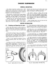
GENERAL DESCRIPTION<br />
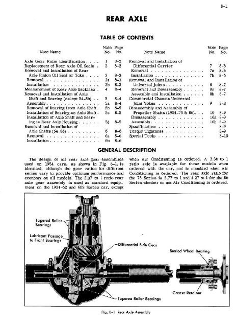
<strong>The</strong> design of all rear axle gear assemblies<br />
us on 1954 care, as shoai In PIg. 8-I, I<br />
fdentical, although the gear rotios for different<br />
series vary to provide aptimom performance aml<br />
economy on all models, <strong>The</strong> 3.07 tO 1 ratio rear<br />
axle gear assembly is used as standard equiptent<br />
on the 1954_SI and 605 Seriee car. except<br />
when jut Conditioning is ordered. A 3.36 to 1<br />
ratio axle Is available or these models when<br />
ordered with the car, and is standard elmen Air<br />
Conditioning is ordered. <strong>The</strong> rear axle ratio for<br />
the 75 Series is 3.77 tel and 4.27 to I for he 86<br />
Series whether or not Air ConditIoning is ordered.<br />
Tnpeed Rode,...<br />
Ben ri £1<br />
Lobricont Passngs<br />
to hnmv Beoringi<br />
V<br />
Differentiol Side Oeor<br />
Senled Wheel Bearing<br />
Fin. S_I<br />
Reot Ada AIae]tbly
8-2<br />
<strong>REAR</strong><br />
<strong>AXLE</strong><br />
<strong>The</strong> axle shaft is of the semi-floating design<br />
with a permanently lubricated and sealed ball<br />
bearing supporting it at the outer end near the<br />
wheels. Axle shaft oil seals are located at the<br />
outer ends of the axle housing, just inside the ball<br />
bearings.<br />
<strong>The</strong> power and braking forces are transmitted<br />
to the frame through the rear springs Hotchkiss<br />
Drive which provides additional cushioning for<br />
all driving strains, resulting in smoother and<br />
quieter operation. Power is transmitted from the<br />
transmission to the rear axle assembly by a<br />
tubular propeller shaft, with "Mechanics" type<br />
universal joints at each end. <strong>The</strong> rear universal<br />
joint cross bearings are attached to the rear axle<br />
pinion yoke by four screws and locks for easy<br />
removal of the propeller shaft from the car. On<br />
all 1954-605 and 62 Series passenger cars, the<br />
sliding joint is located at the rear of the trans<br />
mission. <strong>The</strong> 1954-75 Series passenger car and the<br />
1954-86 commercial chassis use a special yoke<br />
with a threaded plug in combination with a snap<br />
ring on the transmission shaft to lock the yoke to<br />
the transmission output shaft. On these series cars,<br />
the sliding yoke is located at the rear of the rear<br />
propeller shaft assembly.<br />
SERVICE<br />
‘I Axle Gear Ratio Identification<br />
<strong>The</strong> gear ratio of the rear axle assembly on 1954<br />
series Cadillac cars can be determined by an<br />
identifying number on the bottom of the differential<br />
case beneath the center of the pinion shaft.<br />
<strong>The</strong> ratios for the various models are listed<br />
below.<br />
Identification<br />
Series Ratio Number<br />
INFORMATION<br />
seals, as this may cause leakage after installa<br />
tion. Even a slight scratch across the sealing lip<br />
may provide a channel for oil to seep through.<br />
Seals should be soaked in clean motor oil for 1/2<br />
hour before being installed.<br />
After removing the road wheel and axle shaft as<br />
explained in Note 5, the axle seal may be removed<br />
from the rear axle housing.<br />
1954-62, 605<br />
optional<br />
1954-75<br />
1954-86 Comm.<br />
3.07-1<br />
3.36-1<br />
3.77-1<br />
4.27-1<br />
2 Replacement of Rear Axle Oil Seals<br />
Whenever the axle shaft oil seal or the differ<br />
ential pinion shaft oil seal is removed for any<br />
reason, a new oil seal must be installed.<br />
Guard against any bending or denting of the<br />
f3l<br />
"6"<br />
1711<br />
A tool, to facilitate the removal of the axle seal,<br />
may be made up to the dimensions indicated in<br />
Fig. 8-2 and used with the Special Slide Hammer<br />
Assembly. Tool No. J-26l9. Install the plate on the<br />
slide hammer shaft and install a flat washer and<br />
nut on threaded end.<br />
Dimension 62-60S Series 75-86 Series<br />
A<br />
B<br />
C<br />
D<br />
E<br />
F<br />
1/4" 5/16"<br />
3/4"<br />
7/8"<br />
1-1/8"<br />
1-9/16"<br />
2-1/8"<br />
2-9/16"<br />
1-1/4"<br />
1-1/2"<br />
3/16"<br />
3/16"<br />
Seal<br />
-,<br />
Slide the shaft with plate, through seal and pull<br />
shaft outward to position plate against inside face<br />
of seal, Fig. 8-2. Be sure plate isnot behind shoul<br />
der in housing, as it will bend theplate. Drive out<br />
ward with slide hammer to remove seal.<br />
Before installing a new seal, wipe the counterbore<br />
into which the seal is pressed and carefully<br />
remove any nicks or burrs. <strong>The</strong> sealing surface<br />
on the axle shaft should be polished, using 400 grit<br />
"wet" paper and kerosene to insure a smooth sur<br />
face and to prevent wear on the seal.<br />
Fig. 8-2 Rear Axle Oil Seal Removal Tool<br />
<strong>The</strong> surface of the sealing lip should be coated<br />
with lubricant at installation. <strong>The</strong> outside diameter
S -<br />
<strong>REAR</strong><br />
<strong>AXLE</strong><br />
Fig. S-S l,atnlling Rn Asl Oil Sea; Fig. 1-4 checkEng P,eInS Tnqat<br />
of the oil seal meial shield shoLlid be CCC Lcd wiLl,<br />
gond sea Ic:r compno]td berore Installation-<br />
<strong>The</strong> oil seal nr.uS: he pressed sr7uayei y into its<br />
bore and onto its seat. Lao Rear Axle Shaft Oil Seci<br />
Replacer, Tool No. J-359, as shown in Plo. S-N 0<br />
install the rear axle seals on 1954-62-ebS and 75<br />
cars. On 1954-Sd connnercisi chassis useToolNo.<br />
- LISSA.<br />
3 Removal end Installation of Rear<br />
Axle Pinion Oil Seal or Yoke<br />
When it ie neceeeary to replnr.e the tear axle<br />
pinion oil sea I or yoke it Ie very import a Fit l] CL<br />
the pror.cdLlre outlined below be Inilowed to avoid<br />
overloading the pi]]ln,L Ueari]]ge or collapsing the<br />
spacer.<br />
a. Removol<br />
I. Remove aheut I-I/I pints of rear axle lubri-<br />
CL] nt from differential. Lteing a suc.tion no.<br />
2. Remove hoth rear wheels 3.nd brake aroma.<br />
3 Dieconnort rear u,iivaeal .niLlt atpinionyoke.<br />
4. Using a 50 inch pound Lorguc wrench KMO-654<br />
or similar wrenrhi with Socket Tool .j-257l-l.<br />
and Adaptor. Tool No. J -1571-2 ,Lca eLI re the Inc Ii<br />
pounds tOnlIIe reguil red to rotate the pinion shaft<br />
slowly for at lea*. L/2 torm Fig. R-4. Repeat<br />
tni tI rque Chock itt least eight times, which ed II<br />
insure an accurate check over <strong>The</strong> entire circumiv<br />
rcsncc or the ri n C!a r. R cc cr0 all tor qL’C read -<br />
Inge.<br />
that ynk-e can he<br />
ins]nled in seine joaiLio:’Io,i aptiiie.<br />
6. Install Pinion Yoke HoIji-ig Tool, No. ] -2d59,<br />
0]] yoke and II .StC I tWO C tta ching nuts.<br />
I. l:i.stall Skei. ItInJ ho.j-Zi. i_I, Lhraugnhole<br />
ii] II Oh!1, Ig cool onto pin ion nut and remove nut, using<br />
a 7./4 Inch drive sncker wrench.<br />
e move p mi on yoke from pinio]] e IC ii itT’<br />
Ialler, Tool Na. J 5S H. Fig. 8-5.<br />
9. Re- vu union ‘ii sea<br />
Remove .stak:ng burrs on p ]171 no a l-,!!rt with<br />
a eoall file or thread die, si.e 7/5’’ x U.<br />
b, Pntollotion<br />
1. Coat outer edge of nil seal with a e’ coaler<br />
md lubricate scaloig lip. Drive scat il]LO c.arricr.<br />
.ISi]I rail icol Inata 11cr, Tool No. J -‘157. Fig. B_ó.<br />
c:.,uTiUN; be SLICe DIcer ecrfare of yoR’: is<br />
frc iro- scritches or nicks. ‘.?leo:, ‘sin. No.<br />
400 riL ‘we]’’ paper and kerosene.<br />
O’lR: Eefore each check ot. the orql]e, rtlrare<br />
the pinion aT, a it 1/4 urn in e ad recd on to<br />
free it up, thus eliminL ring an unusoalls high<br />
starting torque.<br />
5. Mark pinion ah,,ft and yoke with a punch so Fi1, 5-1 hnc*.*ing Pir;ir Ynke
I<br />
<strong>REAR</strong><br />
<strong>AXLE</strong><br />
‘nrqL]e Wrelirli<br />
Length 13 19 iS 16 I;’ IS 19 20<br />
Torr;oe Required<br />
for 225 ft.<br />
ActLuul 117 122 115 119 III 135 II 141<br />
5. Measure Lhe fnrh pounde trl rqne required to<br />
rotaLc pinion shaft IfS in stepSa. ‘l’hetivoragc torque<br />
reqilirorl should he ro:. a to 7 inch pnLIIIds go corer<br />
tlta,i dir: a’..craRi’ o chu’ torqoe recorded in step So.<br />
Fig. 3-6 lnFinhlEng Pinion Oil Senl<br />
2. 105cC II yoke on pinian shaft ap li;Iea with panci:<br />
ntarke lined up.<br />
3. ] Si all Lie p i nb, not, holding flange of yoke<br />
nIh Pinion Vuke holding Tool, No. J_2eSa..<br />
4. Tigi:Le:L nuL LO 225 it. lbs. torqtle.<br />
NOTEa In eases wherea ldlflh. tnrcJuewrencll<br />
is not ava I Jablo, a Tor qLie W rencr. Eaten eion, I nn I<br />
No. 3-3291, miSs he used with a 200 pound torqLJ<br />
wrench, TonI no. J-12d4. 0 ranv standard 200<br />
pound torque ‘.vrenc i:. Fig. 9-7. A :ab Ic is giva<br />
below [or determining actual tt]rque load on pinion<br />
nut flit ally length of torqoe ‘crc nC. ‘.1 :ied, :0. Cacured<br />
from cenLor of grip to eenre r of d r;vo.<br />
Indicated torque for 225 it. lbs. actsal -225<br />
h/il - L.<br />
5. If torque is low, cigbte:I rho Ji:: lilt emal incrernents<br />
1/2 a flat at a time epprox. and again<br />
measure the torrair 011th Ihe dc:sircd Lo:qLLc is admined.<br />
cal.ITION: On IlOt Over Laghtcn and nov er<br />
back off ttn the It to redtir’a preload torqne. <strong>The</strong><br />
,naxi::LLIm alloccahle torque on oIl ar,sc:Ii,L’i wIth<br />
over lihILi miles a is lncItEIoaaJsIJSe!::.cc:;d an,<br />
10 inch pounds with a new seal. <strong>The</strong> ircrqLle lIlt 0<br />
cats nsacIILhlv Is 50 inch pounce.<br />
7. Stake piniojL shaft into not.<br />
9. Refill rear axle to correct level.<br />
4} Measurement of Rear Axle<br />
Backlash<br />
1. Place car nLI:!;oiL.<br />
2. Pua:eo one end of a ohore of Lu., scek LO the<br />
yoke. c,j. L he d,fie renri t,l pi ni In cli aft, a IC: Led OL:aa<br />
end cm the ra] lie side rh hy meana or ‘‘C’’ chn,pe<br />
trI p reve 0 L lore LiOl] or Lho Ft io:on yoke.<br />
.3 .;‘.eoly clLLcrge:Lcv brake cahle III: one ‘.vl’.,nel Lo<br />
ii revett 7 wIt eel foi,, turn! rg.<br />
4. Mu :Iso ru ro: at’ OLI har Rio a] J or opposi Le I he ci<br />
in inehe .s a L 0.’ Le r Ot-cu’. ole renc: or tire tread, a<br />
stiff wi rep ol LI tC C fa ccc’ ned to doe rends cur car ft a me<br />
cvili aid in this Iooeee.trelneJL.<br />
NOTE: Maximum back 1° s:;:I,.d C: LI Lu .0<br />
col:Jitions should nor exceed<br />
5 Removal and Installation of Axle<br />
Shaft and Bearing Except 54-86<br />
a. Removal of Axle Shaft and Bearing A5sembly<br />
Fig. 8-7 Tightening Pinion Nol<br />
1. DielIt000t read cuheol.<br />
2. Remove tw 5cr cisc hulling broke drLIIII to<br />
axle sh If: Cia IiaO, a.. Id rCc.eve drum.<br />
3. Remove Rur IILLS and lone washers em on7S<br />
series ho 1.-li ng hea r i : to reta ioe r and hack i p lai<br />
to rear axle IaI;.ei..
8-S<br />
<strong>REAR</strong> <strong>AXLE</strong><br />
hly to ted U’’ shaped piece of Rear Kxle Rearing<br />
Remover and Replacer, Tool No. J-29S6, and piece<br />
ott an erIlor press. pig. S -9.<br />
3. Assetlible the rectanguLar shaped pieee of Lilo<br />
tool rtrnencl bearing and over dowela.<br />
C.UTIiN: Step 3 I:;o;r he perfortticd to decrease<br />
ri:e dange r of rite hesrinp exploding while<br />
under erhee :.ireea load.<br />
4. Prese axle shaft through bearing.<br />
Pip. S-B<br />
4. Install wheel Poller, Tool No. J -942-I. 0:1<br />
rear axle ehaft studs and install Slide Elamtiier<br />
ssemhly, Tool No. }-2619 in Puller. Pig. h-h.<br />
5. Remove axle shaft.<br />
Iamovi.’g Reor Aele Sh0rt<br />
CACFION: Be careful not go clsmage axle<br />
shalt oil eeC I when sliding axle shaft out.<br />
b. Removal oF Bearing From Ax’e Shaft<br />
I. i:eing a coid chisel end hamtner, nick the<br />
spacer uext to the hsclring.<br />
NUTS: <strong>The</strong> spacer need nor he split. Cclv<br />
drive chisel into spacer ‘.IIltiI apaeer cat! be<br />
slIpped off shaft.<br />
2, Aesemble rear axle .shaft end bcarilIgeasem-<br />
ksfnhholion of Beariog on Ax]. Shaft<br />
I. irssclllb Is retainer and new be a r itcg o It axle<br />
ft.<br />
2. Place a eselIlilly Lii rough ring of In eta 11cr tool<br />
on arbor l:r eiSa. Fig. 8-9.<br />
3. ees bearing on shaft up to, laIr nLIt qoiLe<br />
:rrchinu si:ockley. Fig. 8-9.<br />
4. Itele ace arhor press aod remove axle shaft<br />
from tool.<br />
5. A a Sen tble ep at-er to shaft and reinstall on eel.<br />
e. Press shaft III roogh spacer to nil spacer Oct<br />
contacts hear lli.<br />
d. In5taIIation of Axle Shaft and Searing in Rear<br />
Axle Housing<br />
I. lospect rear a>Je shaft oil seal for wear Or<br />
Fig. 5-9 0,n r. nnd Insenlling Reor AxI 5,,0fi iearnq
8-6<br />
<strong>REAR</strong> <strong>AXLE</strong><br />
scratches. Replace seal if there is an indication<br />
of leakage, wear, or scratches, as outlined in Note 2.<br />
2. Lubricate inner surface of oil seal leather<br />
with chassis lubricant.<br />
3. Apply film of Lubriplate grease inwheelbearing<br />
bore in axle housing.<br />
next to inner side of wheel bearing.<br />
b. Installation<br />
<strong>The</strong> axle shaft is installed in the reverse order<br />
of its removal, it will be necessary to bleed the<br />
brake line, which was disconnected when the back<br />
ing plate was removed.<br />
4. Install axle shaft shorter shaft on left side,<br />
being careful not to damage oil seal.<br />
NOTE: Before installing an axle shaft after<br />
an oil seal has been replaced, inspect rear<br />
wheel bearing for loss of lubricant, since leak<br />
in old seal may have permitted differential lub<br />
ricant to "wash out" grease in sealed wheel<br />
bearing. A wheel bearing that spins freely indi<br />
cates a lack of grease and should be replaced<br />
at the same time a new oil seal is installed.<br />
5. Install backing plate and bearing retainer.<br />
6. Install four nuts and lock washers six on 75<br />
series on housing bolts, to hold bearing retainer in<br />
place, and tighten by inserting a socket wrench<br />
through hole in rear axle flange.<br />
7. Install brake drum and two retaining screws.<br />
8. Install road wheel, hub cap, and wheel shield.<br />
6 Removal and Installation of<br />
Axle Shafts 54-86<br />
NOTE: Before installing an axle shaft, after<br />
an oil seal has been replaced, inspect rear wheel<br />
bearing for loss of lubricant, since leak in old<br />
seal may have permitted differential lubricant<br />
to "wash out" grease in sealed wheel bearing.<br />
A wheel bearing that spins freely indicates a<br />
lack of grease and should he replaced at the<br />
same time a new oil seal is installed.<br />
7 Removal and Installation of<br />
Differential <strong>Car</strong>rier<br />
NOTE: Any service on the differential carrier<br />
assembly except seal or yoke replacement See<br />
Note 3 should be handled by replacement of the<br />
complete assembly. No disassembly or adjust<br />
ment of this unit should be attempted in the field,<br />
because special equipment is used at the factory<br />
for mating parts and setting side bearingpreload.<br />
a. Removal<br />
1. Disconnect rear universal joint, as explained<br />
in Note 8.<br />
2. Remove lubricant from differential with a<br />
suction gun.<br />
a. Removal<br />
3. Remove axle shafts, as explained in Notes 5<br />
1. DIsmount road wheel. and 6.<br />
2. Remove retaining nut and locking washer from<br />
end of axle shaft.<br />
3. Pull wheel hub and brake drum assembly off<br />
shaft. Use a five jaw puller, similar to Snap-on<br />
Puller, No. J-.4567, with two extra jaws, which will<br />
reduce possibility of warping or distorting brake<br />
drum and will also pull it easier because of equally<br />
distributed tension,<br />
4. Disconnect brake line at wheel cylinder.<br />
5. Remove brake backing plate. <strong>The</strong> axle shaft<br />
is held in the housing by the backing plate which,<br />
when bolted in place, bears against outer race of<br />
wheel bearing.<br />
6. Pull axle shaft and bearing assembly out of<br />
housing, using Rear Axle Shaft and Bearing Puller,<br />
Tool No. J-838. Be careful not to damage oil seal<br />
4. Remove nuts and washers holding carrier to<br />
axle housing and remove entire assembly with<br />
gasket.<br />
b. Installation<br />
Reverse the above procedure using anewcarrier<br />
to housing gasket.<br />
NOTE: In case of lubricant leakage between<br />
the differential carrier and the axle housing,<br />
check the following: First make sure that the<br />
nuts are tightened to the recommended torque<br />
of 30 to 35 ft. lbs. if tightening the nuts does<br />
not stop the leak, an extra gasket should be in<br />
stalled, using a sealer. <strong>The</strong> additional sealing<br />
effect of the extra gasket will prevent further<br />
leakage. If a replacement differential is installed,<br />
special Differential Break-In Lubricant, supplied<br />
by the Factory Parts Department, must be used.
<strong>REAR</strong><br />
<strong>AXLE</strong><br />
8 Removal and Installation of<br />
Universal Joints<br />
½lienever is necessary to dieaesemhle the<br />
or. iv ersal pin Ls for n spec Lion er ave rha ol thc<br />
propeller shaft IiV,ISI be removed from the car.<br />
On 1954 Series 2 and 60s cars. it Is on’y<br />
necessary to remove the cap screws which hold<br />
the bearing houeinge co the rear axle pinion yoke<br />
and slide the propeller shalt and iront yoke oil<br />
the transmission Inaiasllaft.<br />
NOTE: Slide a spare yoke into the trailsmission<br />
excengino housing to prevent oil from<br />
leaking oat.<br />
On 1954-75 and 6 commercial chascia, it Se<br />
neceesary ca remove cap screws tram the univer<br />
sal joint at he cross rniiber as well as rhe screws<br />
at the rear axle pinion yoke. To relriove the front<br />
propeller shaft, it is necessary to remove the cap<br />
screws at the front yoke and also nuts 1flch hold<br />
the center bearing support assembly to the in<br />
sulators at the frame.<br />
a. Removal and Disassembly of Universal Joint<br />
I Remove bearing retainer lock rings from<br />
oulversal joint. as illustrated in Fig. S_lu.<br />
2. SopE’ort the yoke or bearing tronnion on vise<br />
jaws.<br />
3. Ploce Bearing Remover, Toni No.1-4174, over<br />
Fig. B-Il Inleolling Tani on<br />
bearing cap and drive on tool kIndS oniveraai Joint<br />
hearing is out of yoke into tool aboot 1/ inch.<br />
Fig. S-iL<br />
4. Plac.e tool ith bearing in vise Sled tighten<br />
vise until tool holds hearing and drives yoke away<br />
froni tool until hearing is renl oved. Fig. 8-12.<br />
5. Repeat operatIons 2, 3, end 4, on opposite<br />
bearing sod remove cross.<br />
ó. Waeh all parta thoroughly in clean solvent and<br />
inspect hearing hoosing for ikeile nr pits. Replace<br />
any worn or damaged parts.<br />
7. Inspect rerajllers nod e.ork seals sod replace ii<br />
dalllaged or if cork is brittle.<br />
b. Assembly oad Inslallolion<br />
I. Install rollers into bcaring housing and ptic.k<br />
with chassis lubricant.<br />
Fig. 3-ID R,novi,’g Lotk RiI’51 Fig. -I2 Rig bnrng
<strong>REAR</strong><br />
<strong>AXLE</strong><br />
2. install retahier and cork seal on othversal<br />
Joint cross.<br />
3. Start one bearing Into propeller shaft yoke by<br />
tapping lightly with a hanuiler.<br />
4. Install universal joint cross in position and<br />
golds into bearing already started.<br />
5. Start opposite bearIng into propeller shalt<br />
yoke and place in vise ith jaws against bearings.<br />
Fig. 5-13.<br />
6. Tighten vise until cross is just ready to enter<br />
oppositn bearing sied adjust position of ernss until<br />
it enters beth bearings.<br />
7. Tighten vise mdl both hearings are in far<br />
enough to allow lock rings to be installed.<br />
NCiIt: Ii bearinge do not go Into position ith<br />
normal pressure on the vise, a needle bearing<br />
may have fa lieu out of place and the bearing must<br />
be re1neved and needle repositioned.<br />
8. Install lock rings.<br />
Fig. l’-l<br />
Fnatalflog Ronnge<br />
9 Commercial Chassis Universal<br />
Joint Yokes<br />
Wear ill the drive hoe afrer high mileage usaaliy<br />
becomes noticeable as a click at the splines and<br />
splineways of the universal joint yoke on the<br />
transmission malnshaft, and a’ lice oniversel Joint<br />
Fig. -H 75 n Si Propeller Shot, - Dilesiembled
8-9<br />
<strong>REAR</strong><br />
<strong>AXLE</strong><br />
yoke at the rear of the front propeller shaft on spline end.<br />
commercial cars. Correction of this condition is<br />
made<br />
7. Press rubber bushing andbearlngoutof center<br />
by replacing with new yokes as explained<br />
bearing support.<br />
In Notes 8a and 8b. Installation of the new yokes<br />
is made by driving the yoke on the splines of the 8. Remove sealed bearing from rubber insulator.<br />
shaft.<br />
10 Disassembly and Assembly of<br />
b. Assembly<br />
Propeller Shaft 1954-75 & 86 l. Install sealed bearing in rubber Insulator.<br />
a. Disassembly<br />
2. Press bearing and Insulator into bearing sup-<br />
pert.<br />
1. Remove propeller shafts, as explained in 3. Install frontdeflector, bearing support assem-<br />
Note 9.<br />
bly, rear deflector, and fiat washer over spUme.<br />
2. Remove universal Joints from shafts as ex-<br />
4. Press yoke on front drive shaft splines at<br />
plained in Note 9a.<br />
right angles to front yoke. This should be a tight<br />
3. Remove cotter pin, casteflated-nut, lock wash- fit with no backlash or looseness.<br />
er, and flat washer which hold the universal joint<br />
yoke to the spline end of the front propeller shaft. 5. Assemble flat washer, lock washer, and<br />
Fig. 8-14.<br />
castellated nut and tightento4O-50 foot pounds. Back<br />
off 1/2 turn and then install cotter pin.<br />
4. Slide yoke off propeller shaft.<br />
6. Install universal joints In propeller shafts, as<br />
5. Slide large flat washer off shaft. explained in Note 9.<br />
6. Press center bearing assembly off shaft over 7. Install propeller shafts, as explained In Note 8.<br />
SPECIFICATIONS<br />
Subject and Remarks 54-62, ÔOS 54-75 54-86<br />
Axle shaft length<br />
Left 30-1/4" 30-1/4" 32-3/4"<br />
RIght 32-1/2" 32-1/2" 35"<br />
Runout at ground surface near splines<br />
not to exceed .006" .006" .006"<br />
Backlash - pinion and ring gear .003"-.OlO"<br />
Distance - outer face of flange to inner<br />
.003-.010" .003-.010"<br />
end of bearing Inner race 3.075"-3.085" 3.075"-3.085"<br />
Minimum road clearance under center of<br />
axle housing 8" 8-1/4" 9"<br />
Gear Ratio 3.074 3.77-1 4.27-1<br />
Air Conditioner Equipped <strong>Car</strong>s and<br />
optional 62 & 60S 3.36-1 3.77-1 4.27-1<br />
TORQUE TIGHTNESS<br />
Ft. Lbs. Ft. lbs.<br />
Location Size Mm. Max.<br />
Spring U-bolts Special 45 52<br />
Brake backing plate to axle housing 54-86 Comm. 7/16-20 55 60<br />
Brake backing plate to axle housIng 54-62. 605, 75 3/8-24 35 40<br />
Axle shaft hub nuts 86 Comm. 1-14 285 315<br />
Differential carrier to axle housIng 3/8-24 30 40<br />
Pinion shaft nuts 7/8-14 200 Mm.<br />
Universal joint screws 5/16-24 18 22<br />
Intermediate propeller shaft yoke nut 75 & 86 Comm. 1/2-20 40* 5Q*<br />
Differential carrier pedestal clamp screw 1/2-20 50 60<br />
* Back off 1/2 turn. See Note lob, Step 5.
8-10<br />
__<br />
___<br />
<strong>REAR</strong> <strong>AXLE</strong><br />
14B__ ‘VP<br />
I-<br />
L<br />
Hg. 8-15 Rear Axle Special Tools<br />
Key Tool No. Name Key Tool No. Name<br />
A<br />
B<br />
C<br />
D<br />
E<br />
J-1264<br />
J-3264<br />
J-2986<br />
J-55l4<br />
J-942-1<br />
2O0 Torque Wrench<br />
Rear Axle Pinion Yoke Replacer<br />
Set<br />
Rear Axle Bearing Remover<br />
and Replacer<br />
Rear Axle Pinion Yoke Puller<br />
Rear Axle Shaft Puller Adapter<br />
Shown with slide hammer<br />
1-2619-A<br />
F<br />
C<br />
1-I<br />
1<br />
J<br />
J-2623<br />
1-1357<br />
J-4174<br />
J-3069A<br />
J-1355A<br />
Pinion Oil Seal Remover<br />
Shown with slide hammer<br />
J-2619-A and J-838<br />
PInion Oil Seal Replacer<br />
Universal Bearing Remover<br />
Rear Axle Shaft Oil Seal Replacer<br />
Rear Axle Shaft Oil Seal Replacer<br />
54-86 with adapter.<br />
OTHER NOTES AND REFERENCES