1965-1979 part 1 - The Old Car Manual Project
1965-1979 part 1 - The Old Car Manual Project
1965-1979 part 1 - The Old Car Manual Project

Create successful ePaper yourself
Turn your PDF publications into a flip-book with our unique Google optimized e-Paper software.
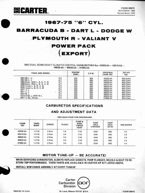
FORM 9997E<br />
NOVEMBER, 1966<br />
Revised March, 1975<br />
6775<br />
''6" CVL.<br />
BARRACUDA 6 - DART L - DODGE W<br />
- PLYMOUTH R - VALIANT V<br />
POWER PACK<br />
(EXPORT)<br />
BBD DUAL DOWN-DRAFT CLIMATIC CONTROL CARBURETORS NOS. 4300SSA - 43015-SA -<br />
4992S-SA - 499s-SA - 6198s-SA<br />
YEAR AND MODEL .<br />
ENGINE<br />
DISPL.<br />
C.F.M.<br />
ORIGINAL<br />
CARB. NO.<br />
ZIP KIT<br />
, NO.<br />
1967-68 L, V SIT<br />
1967.68 L. V AIT<br />
1969-Early; 1970 L, B. R, V, W<br />
SIT<br />
1969-Early; 1970 L. 6. R, V, W A1T<br />
1970 (Late) L, B, R. V, W S/T<br />
1970 (Late) L, &, R, V, W A/T<br />
1971 V, L SIT<br />
1971 V. L A1T<br />
1972 W, L SIT<br />
1972-73 W. L; 1974-75 L AlT<br />
1972 V (So. Africa) A/T<br />
225<br />
225<br />
225<br />
225<br />
225<br />
225<br />
225<br />
225<br />
225<br />
225<br />
225<br />
260<br />
260<br />
260<br />
260<br />
260<br />
260<br />
260<br />
260<br />
260<br />
260<br />
260<br />
4300s-SA<br />
4301s-$A<br />
4300s-SA<br />
4301 S-SA<br />
4992s-SA<br />
4993s-SA<br />
4992s-SA<br />
4993s-SA<br />
4992s-SA<br />
49935-SA<br />
61 98s-SA<br />
902-234A<br />
902-234A<br />
902-234A<br />
902-234A<br />
902-234A<br />
902-234A<br />
902-234A<br />
902-2 J4A<br />
902-234A<br />
902-234A<br />
90 2-234A<br />
CARBURETOR SPEClF ICATIONS<br />
AND ADJUSTMENT DATA<br />
(SEE BACK PAGE FOR PROCEDURE)<br />
PUMP &<br />
GARB. THRO. BOWL FAST FAST<br />
NO.<br />
BORE<br />
CHOKE FLOAT IDLE IDLE<br />
VAPOR<br />
LINKAGE R.P.M.<br />
VENT<br />
UNLOADER<br />
4300SSA 1-71t6 2 Rich 114 1/76 5164 850 114<br />
4301 SSA 1-7H6 2 Rich 114 1116 5164 850 114<br />
4992SSA 1-7116 2 R~ch 114 1/16 5/64 850 114<br />
4993SSA 1-7/16 2 Rich 114 1/16 5164 850 114<br />
6198SSA 1-7/18 2 Rich 114 1116 5/64 850 114<br />
R<br />
INSTALL<br />
MOTOR TUNE-UP - BE ACCURATE!<br />
WHEN SERVICING CARBURETOR, ALWAYS REPLACE GASKETS, PUMP PLUNGER, NEEDLE & SEAT TO RE-<br />
STORE TOP PERFORMANCE. THESE PARTS ARE AVAILABLE IN CARTER ZIP KIT LISTED ABO WE.<br />
NEW CHOKE ASSEMBLY AT EVERY TUNEUP.<br />
PRINTED IN U.S.'A.<br />
<strong>Car</strong>ter r\<br />
<strong>Car</strong>buretor I(CIC.Fr<br />
Division<br />
-<br />
St. Louis, Miasouri 63132 W.S.A.<br />
FORM 9991E
FORM 5685<br />
JANUARY, 1978<br />
DODGE W - PLVMOUTH R<br />
TQ FOUR-BORE DOWN-DRAFT CLllvlATlC CONTROL CARBURETOR NO. 91535<br />
MODEL<br />
ENGINE<br />
DISPL.<br />
C.F.M.<br />
ORIGINAL<br />
CARE NO.<br />
ZIP KIT<br />
NO.<br />
R, W (CALIF.) RIT<br />
440-4<br />
850<br />
91 535<br />
902-329<br />
CARBURETOR SPECIFICATIONS<br />
AND<br />
ADJUSTMENT DATA<br />
SEE BACK PAGE FOR PROCEDURE<br />
CARB.<br />
NO.<br />
BORE<br />
[kc:<br />
STAGE<br />
1<br />
PUMP<br />
STAGE<br />
2<br />
CHOKE<br />
CONTROL<br />
LEVER<br />
CHOKE<br />
BREAK<br />
HfGH LOW<br />
FAST IDLE<br />
CAM<br />
LINKAGE<br />
UNLOADER<br />
BOWL<br />
VAPOR<br />
VENT<br />
91 53s<br />
I-% (PI<br />
2-x tsj<br />
718<br />
112<br />
23/84<br />
3-318<br />
19/32 5132<br />
3/32<br />
511 6<br />
13116<br />
MOTOR TUNE-UP - BE ACCURATE!<br />
WHEN SERVICING CARBURETOR, ALWAYS REPLACE GASKETS, PUMP PLUNGER, NEEDLE & SEAT TO<br />
RESTORE TOP PERFORMANCE. THESE PARTS ARE AVAILABLE IN CARTER ZIP KIT LISTED ABOVE.<br />
INSTALL NEW CHOKE PULL OFF AND/OR CHOKE ASSEMBLY AT EVERY TUNE-UP.<br />
<strong>Car</strong>buretor<br />
Division<br />
Printed in U.S.A.<br />
St. Louis, Missouri 631 32 U.S.A.<br />
FORM 5685
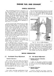
CARBURETQR ADJUSTMENTS<br />
FLOAT LEVEL: With bowl cover inverted, gasket installed and<br />
floats resting on seated needle. the dimension of esch ftoat from<br />
bowl cover aasket to bottom side of floa* at outer end should be<br />
as specified: To adjust, band lever. NOTE: Never aliow lip of<br />
float to be pressed against needle when adjusting.<br />
SECONDARY THROlTLE LINKAGE: Open throttle valves to the<br />
wide open position. <strong>The</strong> primary and secondary throttle shaft<br />
stops. should contact casting at the same time. To adjust. bend<br />
link. Do not attempt to adjust secondary throttle valves to the<br />
wide open position.<br />
SECONDARY THROTTLE LEVER PICK-UP: Apply light pressure<br />
downward on the fast idle screw to move choke control lever to<br />
the wide open choke position. <strong>The</strong> clearance betwen pick-up<br />
lever and rop of secondary lever should be .075". To adiust,<br />
bend rear tang on throttle lever.<br />
PUMP: (STEP II Turn the idle speed screw indward until it iust<br />
touches the stop on throttle fever, then turn in two 12) more<br />
turns. With throttle connector rod installed in the center hole of<br />
pump arm. the dimension from top of bowl cover to top of<br />
plunger shaft should be as specified. To adjust. bend throttle<br />
connector rod.<br />
(STEP 2) With choke valve wids open, open throttle slowly until<br />
the secondary throttle shaft begins to move. Hold in this<br />
position. Measure again from top of bowl cover to top of plunger<br />
shaft. <strong>The</strong> dimension should be as specified. To adjust. bend<br />
pick-up arm on the primary throttle shaft dog.<br />
AIR VALVE OPENING: With air valve wide open there should be<br />
'X" between air horn wall and inner edge of air valw. To adjust,<br />
bend corner of air valva with pliers.<br />
AIR VALVE SPRING: 7. Loosen lock plug. Rotate adjustment plug<br />
(inner) clockwise to allow air valve to position itself to wide<br />
open. 2. Check to see that air valve and shaft are aperating<br />
freely. 3. Tn adjust, rotate adjustment plug [inner) counterclockwise<br />
until air valve just contacts the stop. <strong>The</strong>n turn 1%<br />
additional turn. While holding the adjustment plug in this<br />
position, tighten lock plug.<br />
CHOKE CONTROL LEVER: Off vehicle - place the carburetor on<br />
flat object with surface flush against bottom of flange. Close the<br />
choke valva by pushing on choke laver, with throttle <strong>part</strong>ially<br />
open. Measure the vertical distance from top of rod hole in<br />
control lever down to flat surface simulating carburetor bottom.<br />
This dimension should be as specified. To adjust. bend choke<br />
connector rod.<br />
DIAPHRAGM CONNECTOR ROD: With diaphragm stem fully<br />
depressed and air valve closed, there should be .WOW between air<br />
valve and stop. f o adjust, bend diaphragm connector rod.<br />
CHOKE HIGH AND LOW VACUUM BREAK: (STEP 11 Open<br />
throttle slightly to release the fast idle cam. Seat diaphragm by<br />
using outside vacuum source. Hold levers together with small<br />
clamp. Move choke valve toward the closed position by applying<br />
a light closing pressure to choke rod lever. <strong>The</strong> dimension<br />
between lower edge of choke valve and inner wall of alr horn<br />
should be as specified. To adjust. bend tang that contacts choke<br />
diaphragm rod.<br />
(STEP 21 Remove small clamp fram choke Iwer. Follow the<br />
same procedure as Step 1. <strong>The</strong> dimension should be as wac~fid.<br />
To adjust, place screw driver in tang and bend as requ~red.<br />
FAST IDLE CAM AND LINKAGE: With fast idle screw on second<br />
highest step of fan idle cam, close choke valve as far as possible.<br />
<strong>The</strong> dimension between the lower edge of choke valve and inner<br />
wall of air horn should be as specified. To adjust, bend<br />
connector rod.<br />
UNLOAIDER: With throttle valves wide open. close chok~ as far as<br />
possible without forcing, <strong>The</strong> dimension between lower edge of<br />
choke valve and innar walk nf air horn should be as specified. To<br />
adjust, bend front tang on fast idle control lever.<br />
FAST IDLE ON CAR: With fast idle screw on second step and<br />
against shoulder of first step of cam, adjust fast idle screw to<br />
specified R.P.M. on decal in engine com<strong>part</strong>ment.<br />
SOLENOID OPERATED VENT VALVE, ELECTRIC WlTH<br />
VACUUM ASSIST {IF EOUlPPEDl<br />
1. Solenoid unit must be adjusted before reinstalling on the<br />
carburetor.<br />
2. Measure the dimension between the edge of the solenoid<br />
housing and the vent valve operating lever with a drill of the<br />
proper dimension as listed in the Data Chart.<br />
3. To adjust turn screw (A) on valve Iwer.<br />
4. After adjusting, place rubber valve in arm and install on<br />
carburetor using the proper gasket.<br />
'<br />
PARTS LIST<br />
PART NO.<br />
'1 b.368<br />
7.328<br />
7.334s<br />
11B 487<br />
HE4BB<br />
13.326<br />
13.3275<br />
14,1057<br />
tr1.1058<br />
17.70<br />
*2@239<br />
*20 243<br />
*20 282<br />
21 252A<br />
ZP- 15<br />
Z4 35<br />
2510866<br />
30A 221<br />
a8 376s<br />
53A 5636<br />
61.84<br />
61,761<br />
61 873<br />
61.886<br />
61.915<br />
61.996<br />
61-4'10<br />
61.1104<br />
63.336<br />
63.4268<br />
64.4658<br />
6BBD<br />
65.81<br />
65.07<br />
68.1A<br />
72 85s<br />
' 751946<br />
95 40<br />
101 387<br />
lot nzt<br />
101~5215<br />
101.537<br />
PART NAME<br />
Flenp garksl .....................<br />
Air uelva .......................<br />
Chokevolve eesmbly ................<br />
Aur velve adjustment plug ..............<br />
Arr value lock plug ..................<br />
Chots $hell lavor ...................<br />
Air valve shalt & Imr bwmbly ...........<br />
Chokc counrer%halt laver ...............<br />
Choke lwcr loutof) ..................<br />
Pump dlshsrge check nesdle ...........<br />
Needle rani gssket ................ i2i<br />
Fusl inlet lilting gaakot ................<br />
ldle enr~chmcnt screw gasket ...........<br />
FIOR~ R P ~ ~ ~ ..................<br />
~ I Y izi<br />
Mcrerinq rod arm pin ..............<br />
FIO~~ pin ..................... izi<br />
Noedle & wnl srrambiy .............. 12)<br />
Irllc rnixtura scrcw ................ 121<br />
Pump jct & housing amrnbly ............<br />
For1 rdlo operating arm assembly ...........<br />
Fsrl irlle spood screN sprrns .............<br />
Pump fprlnq twwrrl ...............<br />
Idle mtxrurc & grounding xrsw spring ...... iai<br />
Aur valm spring ....................<br />
Vacuum plrtoo sprmg ................<br />
ldle wood rcrsw sprrng ................<br />
Idla! cnrlchmcnr dlnphrnom spring ..........<br />
Choke modularor rpring .............<br />
Rororner ..................... i5i<br />
Inmke chock reteinsr assembly ....:.......<br />
Pump plungsr eeembly ...............<br />
Step,upcover plnl~<br />
IL-HI ..............<br />
Slcpup cover plaro IR-Hi ..............<br />
Stcpup "iston cowr plate ..............<br />
Alt~~uds cornpunsator ................<br />
Irllc enrichment srrsmbly ............<br />
Mulcrlng rod I 069.'x.048"x.035'7 ....... i2i<br />
Irll. timtcr cap .................. [21<br />
trlle spccd rcrow ...................<br />
Pump orm screw .................<br />
Irjle l.nrlchmenr acrew ...............<br />
i?i<br />
Idlu a!nr~chrnent diaphrspn cover %rew .....(21<br />
PART NO.<br />
PART NAME<br />
101-596 Air choke valve& lever screw .......... I51<br />
101-616 Ewl ewer screw ................ 1101<br />
101.617 Cover plato %crew ................. 151<br />
101-618 Pump jet housing screw ...............<br />
101-628 Dlavhrsgm bracket scrw ...........-...<br />
101.667 Fast idle eperoiing lewr screw ..........<br />
101-680A Aluiuude cempcnrater rcrm ........... i?E<br />
101.693 Chokc counterlhafl lever screw ...........<br />
101.702 Far! ,dle speed rcrcw .................<br />
101410 Idle enrrchrnenl mow Ilong! ............-<br />
lOl.713A Bowl venl solenoid cover ...............<br />
111-110 Mcisring rod arm ...................<br />
111-122 Pumparm ......................<br />
1132JOS Choke coun~srrhelr &lever enemblv ........<br />
114-209 Choke lever ......................<br />
115507 Fasu Idle connector rod .............-..<br />
115-521 Wloke connenor rod .................<br />
115522 Choke duaphrogm connector rod<br />
...........<br />
115552 Throttle connxlw rDd ................<br />
117-190 Pump connccror link .................<br />
120-4M2 Primary mercrlng let {.OW") ...........(2!<br />
rZC-511S Secondary mctering jet 1.110") ...........<br />
121.662 Pump iet housing gasket ..............<br />
121.76% Allllude compenwror gaker .............<br />
121.709 ldle enrichmcnt casting gaxket ............<br />
121.818 Body llnnw qrrkcr ..................<br />
121.858 Bowl ucnr sol#:nord gwker ..............<br />
121.858 Alr hotn sskel ....................<br />
136.308 Choke diephrsgm wnnscror nod waher .......<br />
145.521 Pum~ psrwge rube ..................<br />
145.603 Choke diaohrogm hole ................<br />
156.109 Fuel Inlet luurtq ...................<br />
16B317S Stupup plseon & link ousmbly ............<br />
163.131 lluird X ring ................... 121<br />
164.42 Grommel son! .....................<br />
170.1228 ldlo cnrichmont covw ................<br />
17&14(195 Thcrmostanc coil, houi~ng rod asaembly ......<br />
186.184 Sccorrdary balfle plare ................<br />
202.664s Chokc diaphragm & bracket a-lv ........<br />
203.430$ Idle enrichmoot diaphrnqrn aslembly .........<br />
213.93s Solenold vcnt arrembly ................<br />
NOTE: Figures in parentheses indicete number of pieces used In one carburetor. Where no figure is shown, un!v one is used.<br />
*Available in Zia Kit only.
FORM 5684A<br />
February, 1978<br />
Revised April, 1978<br />
197lg "Vs" DODGE TRUCK<br />
TO FOUR-BORE DOWN-DRAFT CLIMATIC CONTROL CARBURETORS NOS. 9116S - 9117s -91185 -<br />
91498 - 9150s - 9190s<br />
MODEL<br />
ENGINE<br />
DISPL.<br />
C.F.M.<br />
DR1GtNAL<br />
CARB.<br />
ZIP-KIT<br />
NO.<br />
D, W-1.2, B-1.2.3 (CALIF.) A/T<br />
D, W, 8-3, M-3.4.5.6 (CALIF.) AIT<br />
D. W-1,2,3,B-2,3 AIT<br />
M.D. (CALIF.)<br />
AIT<br />
H.D. (CALIF.)<br />
AlT<br />
H.D. [NON-CALIF.)<br />
AIT<br />
H.D. ICALIF.1<br />
AlT<br />
440<br />
440<br />
440<br />
440<br />
440<br />
440<br />
440<br />
850<br />
850<br />
850<br />
850<br />
850<br />
850<br />
850<br />
9116s<br />
91 175<br />
91 18s<br />
9 1495<br />
9 150s<br />
91 51 S<br />
9190s<br />
902-329<br />
902-329<br />
902-329<br />
902-329<br />
902-329<br />
902-329<br />
902-329<br />
CARBURETOR SPECIFICATIONS<br />
AND<br />
ADJUSTMENT DATA<br />
SEE BACK PAGE FOR PROCEDURE<br />
GARB.<br />
NO.<br />
91 18s<br />
THROTTLE<br />
BORE<br />
---<br />
1-1/2(P)<br />
91165<br />
2-114 1s)<br />
1*1/2(P)<br />
2-114 1s)<br />
1-112 (PI<br />
,<br />
9150s<br />
9151s<br />
9190S<br />
2-1/4 lSl<br />
1-112 0')<br />
2-114 ($1<br />
1-112 {PI<br />
*-I/4 is)<br />
'-'I2<br />
2.314 1s)<br />
1*112 Ip'<br />
2-114 IS)<br />
FLOAT<br />
LEVEL<br />
718<br />
718<br />
718<br />
118<br />
718<br />
718<br />
,<br />
PUMP<br />
STAGE STAGE<br />
2<br />
112<br />
f/2<br />
112<br />
'I2<br />
112<br />
112<br />
112<br />
PUMP<br />
ROD<br />
LOCATION<br />
CHOKE CHOKE<br />
CONTROL BREAK<br />
LEVER HIGH<br />
-<br />
3-318 19/32 3/32 3132<br />
1 /2 13164<br />
1 -<br />
3 164<br />
3/64<br />
3/64<br />
5116<br />
23164<br />
23/64<br />
23164<br />
Center<br />
Center<br />
Center<br />
Center<br />
Center<br />
Center<br />
Center<br />
3-318<br />
3318<br />
3-318<br />
3-318<br />
3.318<br />
3-318<br />
19/32<br />
19/32<br />
$9132<br />
19132<br />
19/32<br />
19132<br />
3/32<br />
5/32<br />
3132<br />
3/32<br />
5132<br />
3132<br />
3/32<br />
3132<br />
5/32<br />
3/32<br />
3/32<br />
3132<br />
112<br />
1 /2<br />
112<br />
112<br />
TI2<br />
112<br />
13/64<br />
13164<br />
13164<br />
13164<br />
1 3/64<br />
13/64<br />
MOTOR TUNE-UP - BE ACCURATE!<br />
WHEN SERVICING CARBURETOR, ALWAYS REPLACE GASKETS, PUMP PLUNGER, NEEDLE & SEAT TO<br />
RESTORE TOP PERFORMANCE. THESE PARTS ARE AVAILABLE IN CARTER ZIP KIT LISTED ABOVE.<br />
INSTALL NEW CHOKE PULL OFF AND/OR CHOKE ASSEMBLY AT EVERY TUNE-UP.<br />
0<br />
<strong>Car</strong>ter<br />
QCf\ <strong>Car</strong>buretor<br />
Division<br />
Printed in U.S.A.<br />
St. Louis, Missouri 531 32 U.S.A.<br />
FORM 5684A, Pg. 1
PARTS LIST<br />
PART NAME PART NO.' PART NAME<br />
Grounding adjusting screw (91901<br />
Solenoid & bowl vent operating arm screw<br />
..........<br />
(9f16.17,50.90) .................<br />
Fast idle operating lever screw ............<br />
Choke countershaft lever screw ...........<br />
Fast idle speed screw .................<br />
ldleenrivhment screw (long) (9116,49,90) ......<br />
Bowl vent solenoid cover I91 16,17,49,505 ......<br />
Throdle modulator lock nut (9117,50)<br />
.......<br />
ESAtransducera~mblylocknut~9116,90~ ....<br />
Metering rod arm ...................<br />
Pump arm (9116,17.18,49,50.51) ..........<br />
Choke countershaft & lever assembly ........<br />
Choke lever ......................<br />
Fast idle connector rod ................<br />
Choke connector rod .................. .<br />
715-522 Choke diaphragm connector rod ...........<br />
115-552 Throttle connector rod ................<br />
117-190 Pumpconnectorlink .................<br />
1204098 Primery metering jet 1.098") (9176.<br />
18,49,51,90i .................(21<br />
12-9 Primary metering jet (.099") (9117.50) .....(21<br />
120.5125S Secondary metering jet 4.125") (4117,<br />
18,50,51) ...................(2)<br />
T20-5137S Secondary metering bt (.137") (9116,<br />
49,901 ..................... (2)<br />
*121-662 Pump jet housing gasket ...............<br />
*121-761 Altitudecompensatorgasket(911.6~<br />
.........<br />
*121-787 Body flanw gasket ..................<br />
*l?t-789 idle enrichment casting gasket 19116,49,90)<br />
.....<br />
*121-818 Body flange gasket (9190) ..............<br />
*121-858 Bowl vent solenoid gasket I91 16.17,49,50,90)<br />
....<br />
*121-859 A1rhorngasket(9116,f7,18,4$.50,51~ .......<br />
136-308 Chokediaphragm connectorrod washer .......<br />
*I45521 Pump passage tube ..................<br />
145.603 Choke diaphragm hose ................<br />
*150A-14 Pin spring (9116,181 .................<br />
158109 Fuel inlet fitting ~9116,77,18,49,50,51) .......<br />
756-249 Fuel inlet fitting 19190) ...............<br />
16G317S Stepup piston & link assembly ..........<br />
'163-137 (lud x ring ................... i2j<br />
16441 Grommet seal (9116.17.49,501 ............<br />
16443 Grommet gal (9190) .................<br />
170-1228 ldle enrichment cover I91 16.90) ...........<br />
'170-140s <strong>The</strong>rmostatic coil, housing & rod assembly<br />
(91 16.49.90) ...................<br />
170-14098 ~hermostati coil, housing 8( rod assembly<br />
(9117, t8.50.511 .................<br />
.......<br />
................<br />
.......<br />
18@271 Throttle mcdulator bracket 491 17,501<br />
186.184 Secondary baffle plare<br />
202-583s Throttre madulator assembly (9117.50)<br />
202-664s Choke diaphragm & bracket assembiy<br />
(91 16.49.901 ...................<br />
202466s Choke diaphragm & bracket assembly<br />
(9117, 18,50,511 .................<br />
*203-4305 Idle enrichment diaphragm assembly I91 16,901 ...<br />
213-BOA Transducer assembly (9390) . ............<br />
213938 Solenoid vent assembly (9116,17,44,50,90) .....
FORM 5683<br />
FEBRUARY, 1978<br />
a97a c=wsvg<br />
PLVMOUTH R CHRYSLER C -<br />
DODGE W<br />
TQ FOUR-BORE DUAL DOWN-DRAFT CLIMATIC CONTROL CARBURETOR NOS. 9109S - 97105 - 9'111s - 9712s - 9161s<br />
MODEL<br />
ENGINE<br />
DISPL.<br />
C.F.M.<br />
I<br />
ORIGINAL ,<br />
CARB. NO.<br />
ZIP KIT<br />
NO.<br />
C (Federal)<br />
A IT<br />
C (Altitude, Calif.)<br />
AD<br />
C {Canada)<br />
Am<br />
R, W (Canada) A IT<br />
C (Canada)<br />
AIT<br />
440<br />
440<br />
440<br />
440<br />
440<br />
850<br />
850<br />
850<br />
850<br />
850<br />
9109s<br />
91105<br />
9111s<br />
9112s<br />
9161 S<br />
902-329<br />
902-329<br />
902-329<br />
902-329<br />
902-329<br />
CARBURETOR SPECIFICATIONS<br />
AND<br />
ADJUSTMENT DATA<br />
(Sf E BACK PAGE FOR PROCEDURE3<br />
MOTOR TUNE-UP - BE ACCURATE!<br />
WHEN SERVICING CARBURETOR, ALWAYS REPLACE GASKETS, PUMP PLUNGER, MEEDkE & SEAT TO RESTORE<br />
TOP PERFORMANCE, THESE PARTS ARE AVAILABLE IN CARTER ZIP KIT LIST ED ABOVE.<br />
INSTALL NEW CHOKE ASSEMBLY AT EVERY TUNE UP.<br />
0<br />
<strong>Car</strong>ter<br />
0C-F <strong>Car</strong>buretor<br />
Division<br />
Printed in U.S.A.<br />
St. Louis, Missouri 63132 U.S.A.<br />
FORM 5683
CARBURETOR ADJUSTMENTS<br />
FLOAT LEVEL: With bowl cover Inverted, gasket ~nstalled and<br />
floats resting on seated needle, the dimension of each float from<br />
bawl cover gasket to bottom side of float at outer end should be<br />
as specified. To adiust, bend lever. NOTE. Never allow lip of<br />
float to be pressed against needle when adjusting.<br />
SECONDARY THROTTLE LINKAGE: Open throttle valves to the<br />
wide open position. <strong>The</strong> primary and secondarv throttle shaft<br />
stop, should contact castlng at rhe same time. To adjust, bend<br />
link. Do not attempt to adjust secondary throttle valves to the<br />
wide open position.<br />
SECONDARY THROTTLE LEVER PICK-UP: Apply light pressure<br />
downward on the fast idfe screw to move choke control.lever to<br />
the w~de open choke posit~on. <strong>The</strong> clearance between pick-up<br />
lever and top of secondary lever should be ,075". To adjust,<br />
bend rear tang on throttle lever.<br />
PUMP: (STEP 1) Turn the idle speed screw inward until it just<br />
touches the stop on the throttle lever, then turn In two (2) more<br />
turns. With throttle connector rod rnstalled in the center hole of<br />
pump arm, the dimension from top of bowl cover to top of<br />
plunger shaft should be as specified.<br />
{STEP 21 With choke valve wide open, open throttle slowly until<br />
the secondary throttle shaTt begins to move. Hold in this<br />
position. Measure again from top of bowl cover to top of plunger<br />
shaft. <strong>The</strong> dimension should be as specified. To adjust, bend<br />
pick-up arm on the primary throttle shaft dog.<br />
AIR VALVE OPEMING: With air vatve wide open there should be<br />
'/?" between air horn wall and inner edge of air valve. To adlust,<br />
bond corner of air valve with pliers.<br />
DIAPHRAGM CONNECTOR ROD: With diaphragm stem fully<br />
depressed and air valve closed, there should be .040" between air<br />
valve and stop. To adjust, bend diaphragm connector rod.<br />
CHOKE HIGH AND LOW VACUUM BREAK: (STEP 1) Open<br />
throttle s11ghtEy to release the fast idle cam. Seat diaphragm by<br />
using outside vacuum source. Hold levers together with small<br />
clamp. Move choke valve toward lhe closed position by applying<br />
a light closing pressure to choke rod lever. <strong>The</strong> dimension<br />
between lower edge of choke valve and inner walf of air horn<br />
should 'be as specified. To adjust, bend tang that contacts choke<br />
d raphragm rod.<br />
lSTEP 2) Remove small clamp from choke lever. Follow the<br />
same procedure as Step 1. <strong>The</strong> dimension should be as specified.<br />
To adjust, place screw driver in tang and bend as required.<br />
FAST IDLE GAM AND LINKAGE: With fast idle screw on second<br />
hjghest step of fast idle cam, close choke valve as far as possible.<br />
<strong>The</strong> dimension between the lower edge of choke valve and inner<br />
wall of alr horn should be as specified. TO adjust, bend<br />
connector rod.<br />
UNLOADER: With throttle valves wide open, close choke as far as<br />
poss~bte without forcing. <strong>The</strong> dimension between lower edge of<br />
choke valve and inner wall of air horn should be as specified. To<br />
adjust, bend front tang on fast idle control lever.<br />
ROWL VAPOR VENT ION CAR): With throttle valves set at curb<br />
idle, remove plug from air horn and insen a narrow ruter in hole.<br />
Rest ruler lightly on top of value. <strong>The</strong> dimension from top of<br />
valve to top of casting should be as specified. To adjust, bend<br />
operating lever.<br />
AIR VALVE SPRING: 1. Loosen lock plug. Rotate adjustment plug<br />
(inner) clockwise ta allow air valve to posrtlon itself to wide<br />
open. 2. Check to see that air valve and shaft are operating<br />
freely. 3. To adjust, ratate adjustment plug (Inner) counterclockwise<br />
until air valve just contacts the stop. <strong>The</strong>n turn I%<br />
additional turn. While holding the adjustment plug in th~s<br />
position, tighten lock plug.<br />
CHOKE CONTROL LEVER: Off vehicle - piece the carburetor on<br />
flat oblect with surface flush agalnst bottom of flange. Close the<br />
choke valve bv pushing on choke lever, with throttle <strong>part</strong>~alry<br />
open. Measure the vertical distance from top of rod hole in<br />
control lever down to flat surface simulating carburetor bottom.<br />
This dimension should be as specified. To adjust. bend choke<br />
connector rod.<br />
PARTS LIST<br />
SOLENOID OPERATED VENT VALVE, ELECTRlC WITH VAC-<br />
UUM ASSFST (IF EQUIPPED}: 1. Solenoid unit must be<br />
*<br />
adjusted before reinstalling on the carburetor. 2. Measure the<br />
d~rnens~on between the edge of the solenoid housing and the<br />
vent vatve operating lever with a drill of the proper dimension as<br />
listed in the Data Chart. 3. To adjust turn screw on valve lever. 4.<br />
After adjusting, place rubber valve in arm and Install on<br />
carburetor using the proper gasket.<br />
FAST IDLE ON CAR: W~th fast idle screw on second step and<br />
against shoulder of first step of cam, adjust fast idle screw to<br />
specified R.P.M. on decal in engine com<strong>part</strong>ment.<br />
TRANSDUCER: See car manufacturer's manual.<br />
Par1 No.<br />
PART NAhnc I Par1 No. PART MAME<br />
Flanrlu qnrkel . .<br />
A1: "*Ivv . .<br />
Ctv~kr~ u.llur~urrpmbly<br />
Buwl venu plurr 1rllM. 10. 11.611<br />
Apt v.?tuv ,~CI~U%I~P#>~ pruq , ,<br />
r l ~ r V.IIVP 10~k plllrr . . .<br />
Chok,. $41.,11 I*>,*#<br />
,in* "dl"* ,t>dft 1w4.r ,,,$,~"l,l.,<br />
Choke ~u~,n~rr.rrll.rl~ lauts<br />
Choks: lhx~. :o?rrwl .<br />
Pulllp tl~~chd~azu: ~ 11eut111~ ~ k<br />
h<br />
Nr'udl" 5LW q415kci , ,<br />
I~4.l 11111'1 11ll~olq q.dlk.1 .<br />
IIIIP, 1.111 1whln~111 ~CII~W 1101lLrl .<br />
A ! Bnal vcrll orrerarcrlg orm 141 111 .<br />
bJA-hLI2S Lblpnond npa,rnllrhg 1h:vsr 011emR1r . . . . . . . .<br />
61 BO F.III ~tltl. ~prq.rl $crow 3nrrn.t . . .<br />
61,761 Yvrno hp8lrx IUIHIWJ .<br />
61-R73 lrtlv mrxrvrr. & ~rnundlnfi rcrour rnrlrlo<br />
GI-RRG A,, ~,,IvP ~p,,r*g . . .<br />
lgl.sl? llnwl vl.vi .Ism >ornun 19111. 611 .<br />
, 13i<br />
61-918 Vacuvnl rrnrfr,t> spr snn lr11W. 10, 131 . . . .<br />
61-9211 V,,cqjum p?sr*,n ~l>~rrw) Wlt 1. Gl 1 , , ,<br />
61.8!;6 11lle sopurl rcrl.w spr~rbq .<br />
51 8Efl lrlla 4.r~ ~rhrncnrl~ael~~anm rprlw . . .<br />
61-11110 Choke mndvlelnr $lr#rnq 19117, 611 .<br />
63,336 n~.ii~~r~r~.<br />
834lriS Irslakc clllek rer.lnrwr erlrmllty<br />
6'1,465S Pumo plurkgsr ,~rr~mnlv<br />
G5 110 Sc~p up C,OU## 1>1.11? 1 lL.141 , ,<br />
fir,-R1 S~#.P.IIP crlu.8 r~l.~lb. lH.111<br />
81 1 iU3 ChnLv rnodallalnr rorrnq l!JlU9, 10. 111 . . . .<br />
. . . . . . 151<br />
101.707 I ari 111Ivry1awI rc~vur . . , ,<br />
101,710 I~IP l~l#r?rhrnrrlr rcrcw f1ong119110.1i. 12. 61 I<br />
101,713A 5~tenold vrnr wrevr 19109. 10. 1.2.611<br />
I31<br />
10Sb.Dl CSA lrmlduc~r arrumblv lock nut<br />
111 110<br />
111-122<br />
113-21OS<br />
111120'1<br />
V~-ien~rro rud arm<br />
.. .<br />
i i ~ o n BaawI u#.rlr
FORM 5682A<br />
MAY, 1978<br />
1978 "VW' DODGE TRUCK<br />
TC! FOUR BORE DOWN-DRAFT CLIMATIC CONTROL CARUBURETOR NOS. 9125s - 91298 - 9173s<br />
MODEL<br />
ENGINE<br />
D ISPL.<br />
C. F.M.<br />
ORIGINAL<br />
CARB. NO.<br />
ZIP KIT<br />
NO.<br />
0, W-7.2. B-1.2.3 M1T<br />
0, W-1.2. 8-1.2.3 AIT<br />
H.D.<br />
360<br />
360<br />
360<br />
850<br />
850<br />
850<br />
91255<br />
9126s<br />
91735<br />
902-329<br />
902-329<br />
902-329<br />
CARBURETOR SPECIFICATIONS<br />
AND<br />
ADJUSTMENT DATA<br />
(SEE RACK PAGE FOR PROCEDURE)<br />
CARB.<br />
NO,<br />
9'25s<br />
26S<br />
THROTTLE<br />
BORE<br />
1-112 (PI<br />
2-114 ($1<br />
1*112{P)<br />
2-1 14 (S)<br />
1-112(P)<br />
2-114 (S)<br />
FLOAT<br />
LEVEL<br />
7/8<br />
718<br />
718<br />
PUMP<br />
STAGE STAGE<br />
2<br />
PUMP<br />
ROD<br />
LOCATION<br />
LEVER<br />
--------<br />
112<br />
112<br />
17/32<br />
5/16<br />
5/16<br />
9/64<br />
Center<br />
Center<br />
Center<br />
CHOKE<br />
CONTROL<br />
3-318<br />
3-318<br />
3-318<br />
CHOKE<br />
BREAK<br />
HIGH LOW<br />
19132<br />
19/32<br />
19/32<br />
5/32<br />
3132<br />
9/64<br />
FAST IDLE<br />
CAM<br />
LINKAGE<br />
3/32<br />
3/32<br />
3/32<br />
UNLOADER<br />
112<br />
112<br />
7/64<br />
BOWL<br />
VAPOR<br />
VENT<br />
-<br />
13/64<br />
13164<br />
1 3164<br />
MOTOR TUNE-UP - BE ACCURATE!<br />
WHEN SERVICING CARBURETOR, ALWAYS REPLACE GASKETS, PUMP PLUNGER, NEEDLE % SEAT TO RESTORE<br />
TOP PERFORMANCE. THESE PARTS ARE AVAILABLE IN CARTER ZIP KIT LISTED ABOVE.<br />
INSTALL MEW CHOKE ASSEMBLY AT EVERY TUNE-UP.<br />
n <strong>Car</strong>ter<br />
<strong>Car</strong>buretor<br />
Division<br />
Printed in U.S.A.<br />
St. Louis, Missouri 631 32 U.S.A.<br />
FORM 5682A
FORM 5680<br />
February, 1978<br />
1978 "-V8"<br />
CHRVSLER CI- DODGE W<br />
CORDOBA - S PLYMOUTH R<br />
CHARGER X - ASPEN N - VOLARE H<br />
CeBARON F - DIPLOMAT G<br />
TQ FOUR-BORE DOWN-DRAFT CLIMAT lC CONTROL CARBURETORS NOS. 9104s - 9134s<br />
MODEL<br />
H. N. R, W, s, X A/T<br />
H,N,F,G.R,W,S.X.C<br />
AIT<br />
ENGINE<br />
DISPL.<br />
360-4<br />
360-4<br />
I<br />
C.F.M.<br />
850<br />
850<br />
ORIGINAL<br />
CAR8 NO.<br />
91045<br />
91 34s<br />
ZIP KIT<br />
NO.<br />
902-329<br />
902-329<br />
CARBURETOR SPECIFICATIONS<br />
AND<br />
ADJUSTMENT DATA<br />
SEE BACK PAGE FOR PROCEDURE<br />
MOTOR TUNE-UP - BE ACCURATE!<br />
WHEN SERVlClNG CARBURETOR, ALWAYS REPLACE GASKETS, PUMP PLUNGER, NEEDLE & SEAT TO<br />
RESTORE TOP PERFORMANCE. THESE PARTS ARE AVAILABLE IN CARTER ZIP KIT LISTED ABOVE.<br />
INSTALL NEW CHOKE PULL OFF ANDIOR CHOKE ASSEMBLY AT EVERY TUNE-UP.<br />
n <strong>Car</strong>ter<br />
<strong>Car</strong>buretor<br />
Division<br />
Printed in U.S.A<br />
St. Louis, Missouri 631 32 U.S.A. FORM 5680
FLOAT LEVEL: Wlth bowl cover inverted, gasket installed and<br />
floats resting on seated needle, the dimension of 'each float<br />
from bowl cover gasket to bottom side of froat at outer end<br />
should be as specified. To adjust, bend lever. NOTE: Never<br />
allow lip of float to be pressed against needle when adiustinq.<br />
SECONDARY THROTTLE LINKAGE: Open throttle valves to<br />
the wide open position. <strong>The</strong> primary and secondary rhrottle<br />
shaft stops, should contact casting at rhe same time. To adjust,<br />
bend link. Do not attempt to adlust secondarv throttle valves<br />
to the wide open position.<br />
SECONDARY THROTTLE LEVER PICK-UP: Apply light pressure<br />
downward on the fast idle screw to move choke control lever<br />
to the wide open choke position. <strong>The</strong> clearance between pick-up<br />
lever and top of secondary lever should be .075".,To adjust,<br />
bend rear tang on throttle lever.<br />
PUMP: (STEP 1) Turn the idle speed screw inward until it just<br />
tauches the stop on throttle lever, then turn in two (2) more<br />
turns. With throttle connector rod installed in the inner hole<br />
on (91041; outer hole (91341, the dimension from top of bowl<br />
cover to top of plunger shaft should be as specified. To adjust,<br />
bend throttle connector rod.<br />
(STEP 2) With choke valve wide open, open throttle slowly<br />
until the secondary throttle shaft begines to move. Hold in this<br />
position. Measure again from top of bowl cover to top of<br />
plunger shaft. <strong>The</strong> dimension should be as specified. To adjust,<br />
bend pick-up arm on the primary throttle shaft dog.<br />
CARBY RETOR ADJUSTMENTS<br />
hole in control lever down to flat surface s~mulating carburetor<br />
bottom. This dimension should be as specified. To adjust, bend<br />
choke connector rod.<br />
DIAPHRAGM CONNECTOR ROD: With d~aphragm stem fully<br />
depressed and air valve closed, there should be ,040" between<br />
air valve and stop. To adjust, bend diaphragm connector<br />
rod.<br />
CHOKE HlGH AND LOW VACUUM BREAK: (STEP 7E Ooen<br />
throttle sllahtlv to release the fast idle cam. Seat dia~hriarn<br />
bv using iutslde vacuum source. Hold levers together ~7th<br />
small clamp. Move choke valve toward the closed pos~tion by<br />
applying a light closing pressure to choke rod lever. <strong>The</strong><br />
dimension between lower edge of choke valve and inner wall<br />
of air hose should be as specified. To adjust, bend tang that<br />
contacts choke diaphragm rod.<br />
(STEP 2) Remove small clamp from choke lever. Follow rhe<br />
same procedure as Step 1. <strong>The</strong> dimension should be as specified.<br />
To adjust, place screw driver in tang and bend as required.<br />
FAST IDLE CAM AND LINKAGE: With fast Fdle screw on second<br />
highest step of fast idle cam, close choke valve as far as possible,<br />
<strong>The</strong> dimension between the lower edge of choke valve and inner<br />
wall of air horn should be as specified. To adjust. bend connector<br />
rod.<br />
UNLOADER: With throttle valves wide open. close choke as far<br />
as possible without forcing. <strong>The</strong> dimension between lower edge<br />
of choke valve and inner wall of air horn should be as specified,<br />
AIR VALVE OPENING: With air valve wide open there should be To adjust, bend front tang on fast idle control lever.<br />
'A" between air horn wall and inner edge of air valve. To adjust,<br />
bend corner of air valve with pliers. SOLENOID OPERATED VENT VALVE. ELECTRIC WITH<br />
VACUUM ASSIST (IF EQUIPPED): 1. Solenoid unit must be<br />
AIR VALVE SPRING: 1. Loosen lock plug. Rotate adjustment<br />
plug (inner) clockwise to allaw air valve to position itself to<br />
wide open. 2. Check to see that air vahe and shaft are operating<br />
freely. 3. To adjust, rotate adjustment plug (inner) counterclockwise<br />
until alr valve just contacts the stop. <strong>The</strong>n turn 1%<br />
additional turn. While holding the adjustment plug in this<br />
position, tighten lock plug.<br />
CHOKE CONTROL LEVER: Off vehicle - place the carburetor<br />
on flat object with surface flush against bottom of flange.<br />
Close the choke valve by pushing on choke lever, with throttle<br />
<strong>part</strong>ially open. Measure the vertical distance from to^ of rod<br />
adjusted before reinstalling on the carburetor. 2. Measure the<br />
dimension between the edge of the solenoid housing and the<br />
vent valve operating lever with a dri4l of the proper dimension as<br />
listed in the Data Chart. 3. To adjust turn scrw (A3 an valve<br />
lever. 4. After adjusting, place rubber valve in arm and instali on<br />
carburetor using the proper gasket.<br />
FAST IDLE ON! CAR: With fast idle screw on second step and<br />
against shoulder of first step of cam, adjust fast idle screw to<br />
specified A.P.M. on decal in engine com<strong>part</strong>ment.<br />
TRANSDUCER: See car manufaaurer" manual.<br />
PARTS LIST<br />
PART NO. PART NAME PART NO. PART NAME<br />
*1A-36B Flange gasket .......................<br />
7-328 Air valve ..........................<br />
7.3345 Choke valve assembly ...................<br />
110-487 Air valve adjustment plug<br />
.................<br />
118-488 Air valve lock plug .....................<br />
13.326 Choke shaft lever ......................<br />
13-327s Air valve shall & lever assembly .............<br />
14.1057 Choke countershafr lever .................<br />
14-1058 Choke lever (Outer) ....................<br />
77-70 Pump discharge check needle ...............<br />
'20-239 Needle seat gasket .................. (21<br />
*2&243 Fuel inlet fittrng gasket ..: ...............<br />
*2@282 Idle enr~chment screw gasket ...............<br />
21-2528 Float assembly ...................(21<br />
24-15 Metering rcd arm pin .........:<br />
.........<br />
24-35 Floar pqn ....................... 121<br />
'2510865 Needle & seat assembly ............... 121<br />
30A-221 Idle mixture screw .................. 121<br />
48-376s Pump jet & housing assembly 19134) ..........<br />
483835 Pump jet & housing assembly 19104) .........<br />
53A-563s Fasl ~dte operating arm assembly (9104) ........<br />
53A-5825 Solenold operating lever assembly 19104) ........<br />
61-84 Fast Idle speed screw spring ................<br />
61-762 Pump spring (Upper1. ...................<br />
61-873 Idle rnlxture & grounding screw spring (31 .......<br />
61-886 Aur valve spring .......................<br />
61.915 Vacuum plston spring ...................<br />
61-956 Idle speed screw spring ..................<br />
*El-970 ttfle enrichment diaphragm spring ............<br />
61-1 103 Choke modulator spring 191 34) .............<br />
61-13 W Choke modulator spring 191041 ............<br />
151<br />
'63-336 Retamer ........................<br />
*63-426s Illtake check retainer assembly ..............<br />
"64.465s Pump plunger assembly ..................<br />
6580 Step-up cover plate 1L-HI .................<br />
65.81 Step-up cover plate IR-H1 .................<br />
6584 Step-up plslon cover plate. ................<br />
72.395 Idle enr~chment assembly (9134) .............<br />
72-101s Idle enr~chrnenl assembly (9104) ............<br />
75-1940 Metering rod 191041 ....................<br />
75-1996 Moter~c~g rod I91 341 ....................<br />
96-40 Idle lim~ter cap .................... 121<br />
101.387 Idle speed screw (91341 ..................<br />
101-421 Pump arm screw ......................<br />
101-505 Solenold bracket screw 191041 ..............<br />
101-521s Idle enr~chment screw (91041 ............<br />
101-537s ldle enrichment diaphragm cover screw ..... 12)<br />
101-596 Air choke valve & lever screw ............ 15)<br />
101-616 Bowl cover screw ..................(101<br />
101-517 Cover plate screw ..................(31<br />
101-618 Pump let housine screw .................<br />
101-628 P~aphragrn bracket screw ................<br />
101-629 Grounding adjustment screw 49104) ...........<br />
101-635 Solenold bowl vent operating arm scrcw 191041 ....<br />
101-687 Fast idle aperarlng lever screw ............<br />
101-593 Throttle slialt screw<br />
..................<br />
101-702 Fast rdle speed screw ...............<br />
101-710 Idle enrichment screw (long) ............<br />
101-713A Bowl vent svlcnard cover ................<br />
105-87 ESA transducer assembly lock nur 197041 .....<br />
171-110 Metering rod arm 191341<br />
...............<br />
111-123 Pump arm 491041 . . . . . . . . . . . . . . .<br />
113-210s Choke countershalt & Ir!vcr assemblv . . . . . .<br />
134-209 Choke tever ........................<br />
115-507 Fast Idle corlnector rod ...............<br />
115-521 Choke connector rod<br />
135-522 Choke diaphragm conr~eclor<br />
..................<br />
rod .............<br />
115-552 Throtlle connector rud ......... - - - ..<br />
117-190 Pump ccnfiecror lank ...................<br />
120-4032 Primary rnelerrng let (9102) .......... 12)<br />
120-5110s Secondary meterlng iet ............... 121<br />
*121-662 Pump jer housing gasket ..................<br />
* 721-789 Idle enrlchmerlr castrl~g<br />
*121-818 Body flange gaskei ....................<br />
*I 21-858 Bowl vent solenoid gaskcr ..............<br />
gasket .............<br />
121-859 Air hurn gasket ....................<br />
136-308 Choke d~aphragm connector rod washer .........<br />
145-521 Pump passage tube ..................<br />
145.603 Choke d~aphragm hosr! . . . - - - .- . ,.<br />
156-109 Fuel 1r11er fttt~rlg ....................<br />
150-317s Step-up plslurl & I~nk assembly ............<br />
(21<br />
170-1228 Idle e~lr~chment cov~?r ..................<br />
170-1407s <strong>The</strong>rmostat~c COI!, housing & rod assembly .......<br />
'163-131 Quad X rlrlg . .................<br />
186-184 Secondary baffle plalc .................<br />
202-6655 Choke diaphragm & bracket assembly ..........<br />
+203-1305 Idle enruchrnent diaphragm ...............<br />
213-80A ESA trau>sducer assembly (91 04) . ...........<br />
213-93s Sulenatd venr assemblv .................<br />
213-98A Ground wlre & bracket assembly (9104) ........<br />
'Parts sold in Zip-Kit Only<br />
NOTE: Figures in par~othzsis rndicare number of pieces us& in one carburetor. Where no figure is shown only one is used.
'<br />
FORM 5681<br />
Januarv. 1978 . .<br />
1 7<br />
V<br />
DODGE W<br />
CORDOBA S--PLYMOUTH R<br />
CHARGER X - ASPEN N - VOLARE H<br />
LeBARON F - DlPLOMAT G<br />
DODGE TRUCK<br />
TQ FOUR-BORE DOWN-DRAFT CLIMATIC CONTROL CARBURETORS NOS.<br />
MODEL<br />
D, W, B-1, 2, 3 Dodge Trk. M IT<br />
D, W, 8-1, 2, 3 Dodge Trk. An<br />
H. N, F, G, R, S, X (Canada) An<br />
H, N, F.G. R,S, X1Calif.l An<br />
Dodge Truck L, D. (Canada)<br />
Am<br />
9123s - 9124s - 91373 - 9'1475 - 91528<br />
ENGINE<br />
DISPP.<br />
37 84<br />
3184<br />
3184<br />
318-4<br />
318-4<br />
C.F.M.<br />
285<br />
285<br />
285<br />
285<br />
285<br />
ORIGINAL<br />
CARB NO.<br />
91 23s<br />
Y 1 24s<br />
91 375<br />
91478<br />
91 528<br />
ZIP KIT<br />
NO.<br />
902-329<br />
902.329<br />
902-329<br />
902-329<br />
902-329<br />
CARBURETOR SPECIFICATIONS<br />
AND<br />
ADJUSTMENT DATA<br />
SEE BACK PAGE FOR PROCEDURE<br />
UNLOADER<br />
MOTOR TUNE-UP - BE ACCURATE!<br />
WHEN SERVICING CARBURETOR, ALWAYS REPLACE GASKETS, PUMP PLUNGER, NEEDLE & SEAT TO<br />
RESTORE TOP PERFORMANCE. THESE PARTS ARE AVAILABLE IN CARTER f lP KIT LISTED ABOVE.<br />
INSTALL NEW CHOKE PULL OFF AND/OR CHOKE ASSEMBLY AT EVERY TUNE-UP.<br />
r\ <strong>Car</strong>ter<br />
[QC-I <strong>Car</strong>buretor<br />
Division<br />
Prlnted in U.S.A.<br />
St. Louis, Missouri 63132 U.S.A. FORM 5681
CARBURETOR ADJUSTMENTS<br />
FLOAT LEVEL: Wrth bowl cover inverted, gasket installed and DIAPHRAGM CONNECTOR ROD: W~th d~aphragm stem fully defloats<br />
restlng on seated needle, the d~mension of each tloat from pressed and a11 valve c.losed, there should be ,040" betmn air<br />
bowl cover gasket to bottom side of float at outer end should he valve anri stnp To adlust. *>end diaphraam connector rod.<br />
as specifled. To adjust, bend lever. NOTE: Nwer allow lip of CHOKE HIGH AND LOW VACUUM B R f ~ ~ (S~EP : 1 Open<br />
@<br />
float to be pressed against needle with adjusting.<br />
thrr)ltle sltghlly to reledse the last rdle cam. Seat diaphragm by<br />
SECONDARY THROTTLE LINKAGE: Open throttle values to the using c~ulstde vacuum source. Hold levers together w~th small<br />
wrde open position <strong>The</strong> primary and secondary throttle shaft clamp Move choke valve toward the closed position by applying<br />
stops, should contact ~astina at the same time. To adiust. bend a liaht clns~nu DreSsUrE to choke rod lever. <strong>The</strong> dimens~on belink.<br />
Do not attempt to adlust secondaw throttle valves to the tween lower edge nf choke valve and inner wall of air horn<br />
wade open pes~tion.<br />
shnuld be as spec~fred. To adjust, bend tang that contacts choke<br />
draphlaqm rod<br />
SECONDARY THROTTLE LEVER PICK-UP: Apply liaht pressure<br />
downward on the fast idle screw to move choke control lever to (STEP 2) Rernt~ve small clamp from choke lever. Follow the<br />
the wide open choke posit~on. <strong>The</strong> clearance between pick-up same procedure as Step 1. <strong>The</strong> dimension should be as specified.<br />
lever and top of secondary lever should be ,075". To adjust, Ta adjust, place screw dr~ver In tang and bend a$ required.<br />
bend rear tang on throttle lever.<br />
FAST IDLE CAM AND LINKAGE: With fast Idle screw on second<br />
PUMP: (STEP 1) Turn the idle speed acrew inward until it just hlqhest step 01 fast ~dle cam. close choke valve as far as possible.<br />
touches the stop on rhrottle lever, then turn in two (2) more <strong>The</strong> dlrn~r~slon hcrwesn the lower edge of choke vdlve and Inner<br />
turns With throttle connector rod installed in the hole as speck wall ot d11 hrwn shrruld be as specrfled. To adjust. hend connecfied<br />
of pump arm, the dimension from top of bowl cover to top ll>l inli.<br />
of plunger shaft should be as specified. To adjust, bend throttle<br />
connector rod.<br />
UNLOADER: W11h thrr~rrle valves wide ODen. clcse choke as far as<br />
(STEP 2) With choke valve wide open, open throttle slowly unt~l<br />
the secondary throttle shaft begins to move. Hold In this positian.<br />
Measure agaln from top of bowl cover to top of plunger<br />
shaft. <strong>The</strong> dimension should be as specified. To adjust, bend<br />
pick-up arm on the primary throttle shaft dog.<br />
CHOKE CONTROL LEVER: Off vehicle - place the carburetor on<br />
flat object w~th surface flush against bottom of flange. Close the<br />
choke valve by pushing on choke lever, with throttle <strong>part</strong>ially<br />
open. Measure the verttcaf dlstance from top of rod hole in<br />
control lever down to flat surface simulating carburetor bottom.<br />
This dimension should be as specified. To adjusr, bend choke<br />
connector rod.<br />
AIR VALVE OPENING: W~th air valve wide open there should be<br />
Wr between air horn wall and inner edge of air valve. To adjust,<br />
bend corner of air valve with pliers.<br />
AIR VALVE SPRING: 1. Loosen lock plug. Rotate adjustment plug<br />
(inner) clockwise to allow air valve to position itself to wide<br />
open. 2 Check ta see that air valve and shaft are operating<br />
freely. 3. To adjust, rotate adjustment plug (inner) counterclockwise<br />
until air valve just contacts the stop. <strong>The</strong>n turn 1%<br />
additional turn. While holding the adjustment plug in this position,<br />
tighten lock plug<br />
I-ART NO. PART NAME<br />
*1A-388 Flange gasket<br />
....................<br />
7-328 Air vdlve .....................<br />
7-3345 Choke value asmmbly .................<br />
*118.294 Bowl vonr plug 19137) ................<br />
118-187 Air valvo adjustment plug ...............<br />
118.488 Air value lock plug ..................<br />
Choke shafi lwer ...................<br />
Air valve shefr & lever assembly ............<br />
Choke counisrshafl lever ...............<br />
Choko lever Iouterl ..................<br />
Ptrma disch~rge check nsedle ...........<br />
Needle sear gasket ................. i2i<br />
Fuel inlet fitting galkst ..............<br />
Float assembly .................. i2i<br />
Meroring rod rrnn pin .................<br />
Solenoid vent pin 191521 .............<br />
FIOSI pin ..................... izi<br />
Needle & seet assembly .............. 12)<br />
Idle mixture rcrsw ................ 12)<br />
Pump jet & housmg asmbly .............<br />
Bowl vent operating lever assembly (91371 ......<br />
Fast idle cporeting arm assembly (9123.24,47,52) . .<br />
$owl vent arm (91371 ................<br />
Solenoid opsreting lever aswmbly (9137.471 .....<br />
Fast ~dle speed screw spring ..............<br />
Pump spring luppar) ..............<br />
Idle mixture & grounding rcrew spring .....: i3i<br />
Air valve spring ....................<br />
Bowl vnnt arm spring 19131) .............<br />
Vacuum piston sprrng I9123,24,37.471 ........<br />
Idle spesd =re* rpri ................<br />
Choke modularor spring ..............<br />
Rsmnor ......................(Si<br />
Inieke check rstarnef asrsmbly ............<br />
Pump plunger asmmhly ................<br />
S~ewua cover plats 1C.H) ...............<br />
Sreo-up cover plnie (R-H I ...............<br />
Siepup piston cover plate ..............<br />
Alrrtuds compensaror 19147) .............<br />
...<br />
Mererrng rod (.064" x ,048" r .03!3'1 19147) 12)<br />
Motoring rod 4,067" r .MY x ,035") 19123.24.521 121<br />
M~tering rod (.070" x .057" x .04W4! 19137) 121<br />
...<br />
Idle lrmiter cap .................. 12)<br />
ldln wsed xrew I91 23,24,52) ............<br />
Puma orm screw ...................<br />
Solenord brackol screw {913?,47.521 .........<br />
Idle snrichmenr screw (9147) .............<br />
Alr chake valve & lever screw ...........(51<br />
PARTS LIST<br />
. .<br />
l~ctwt!en lower edg of<br />
p(~rs~tllr, w~lh(~ul tc~rrcng. <strong>The</strong> d~msns~ol\<br />
chokr. vitlvr and Inner wall of alr horn should he ;as specified. To<br />
adlnsl, trt!r~rl f~ontans on fast tdle control lever<br />
BOWL VAPOR VENT ION CARI: With throltle vdlues set at curb<br />
rclln, ternout! pluq from ar horn and Insert a narraw ruler In hole.<br />
RPSI r t~lw llrlhlly nn lop of valve. <strong>The</strong> d~mrns~on from top of<br />
valve Irr top rsf castlnq should he as sperrlted Tu adrust, bend<br />
opere~tina Itwt!r<br />
SOLENOID OPERATED VEHT VALVE, ELECTRIC WITH<br />
VACUUM ASSlST (IF EQU IPPEDJ<br />
1 Snlpr~o~rl urirt must he ad]rtsted before reinstalling on Fhe<br />
can t~uretor .<br />
2. Measure the drmenslon between the edge of the solenoid<br />
houstng and the vent valve operating lever wlth a dr~ll of the<br />
pcoprr drmens~on as l~sted In the Data Chart.<br />
3. To atllusr iurn scrpw on valve lever.<br />
4. After adjust~ng, place rubber valve In arm and install on<br />
carburetor uslng the proper gasket.<br />
FAST IDLE ON CAR: W~th fast idle screw on second step and<br />
against shoulder of first step of cam, adjust fast idle screw to<br />
specified R.P.M. on decal in engine com<strong>part</strong>ment.<br />
f RANSDUCER: See car manufacturer's manual.<br />
1 PART NO. PART NAME<br />
10.1.616 Bowl cwer screw<br />
201.617 Cover plate screw<br />
101-618 Pump let hous~ng<br />
101-628 Dlaphra~ bracket screw<br />
101-629<br />
101.635<br />
Grounding adlusting screw (9137.471<br />
Solenohd &bowl vent owretinaarm Kraw<br />
..............<br />
..............<br />
screw ...........<br />
..........<br />
....<br />
19137.47. 521 ..................<br />
TOT467 Fasr Idle operarlng lever xrew ...........<br />
101.693 Choke countershaft lever xrew ............<br />
101-702 Far1 ldls speed mew (9323.24.47.521 ........<br />
101.713A Selsn<strong>Old</strong> veni screw .............. (3)<br />
10SA.81 ESA rranMucer armblv lock ............<br />
111110 Meterlnqrodarm .................<br />
111122 Pumparm .......................<br />
113~2105 Choke countershaft & lwer arsemblv ........<br />
118-209 Choke leuer<br />
118.500 Bowl vent connecror rod ..............<br />
115-507 Fast Idle conneclor rod ................<br />
115.521 Choke connsctoc rod .................<br />
115-522 Choke d~aohrwm connector rod ...........<br />
115.552 Throttlc conn~ctorod ................<br />
117.190 Pump eonnsctor link<br />
.............<br />
320-4092 Prurnarv rneterrng let 1.092'") ..........: i2i<br />
120 51105 Secondarv melerlnq jet 1.1 10") ......... (2)<br />
-127.662 Pump let hous~ngasket ..............<br />
"127.761 Al~kcude comosnraror gasket 19147) .........<br />
"121.818 Body flangegasket ..................<br />
*121.858 Bawl vsnt solanord gasket ...............<br />
'121 859 Arr horn gesket ...................<br />
136-300 Throttle shaft sprlng warher 19123. 24. 37) ......<br />
736.308<br />
'745.521<br />
Chokedla~hragmconncctor rod washer ......<br />
Pump passage tube ..................<br />
745-603 Choke d~aphragm<br />
hore ..............<br />
145,622 Tube (9123.241 ..................!?i<br />
*t50A.14 'Pnn sarnng .......................<br />
156.109 Fuel Inlet fittrng ...................<br />
156.182 Tee (4123.241 ....................<br />
160 3178 Step-up prsian & lrnk assembly ..........<br />
*163131 QuadXr~ng.. ................ .izi<br />
*16&30 Grommet wal(91371 ................<br />
-164 43 Grammet sesl (9123.24.47.52) ............<br />
170-1d0E <strong>The</strong>rmortar~c toll, housing & rod arsernbly ......<br />
186.184 Secondary baffle plate ................<br />
202 665s Choke d~aphragm lP breckst esrembly ........<br />
213 BOA ESA Iranducer asmbly (9131.47) .........<br />
213.338 Solenord vent ammbly (9123.24.47.521 .......<br />
213.98A Ground *Ire & bracket nsaembly (9137.471<br />
NOTE; Figurss in perentheser indicate number 01 piaces uswd in one CUrbUfatQr. Where no figure is shown, only one is used.<br />
'Ports available in Zip-Kit only.<br />
....
FORM 5679A<br />
JANUARY, 1978<br />
Revised April, 1978<br />
1 "6"'<br />
DODGE W. - PLYMOUTH, R<br />
ASPEN N - VOLARE H<br />
Le BARON F - DIPLOMAT G<br />
DODGE TRUCK<br />
BBD DUAL DOWN-DRAFT CLIMATIC CONTROL CARBURETOR NOS. 8143s - 81565 - 8175s - 8201s<br />
MODEL<br />
ENG.<br />
DISPL.<br />
C. F.M.<br />
ORIGINAL<br />
CARB.<br />
ZIP KIT<br />
NO.<br />
H, N, F, G, R. W, S, X (Altitude) AIT<br />
D, W. 6-1 AIT<br />
H, N, F, MlT<br />
H, N, F, G. R, W, S, X (Export) A/T<br />
318<br />
318<br />
318<br />
318<br />
285<br />
285<br />
285<br />
285<br />
81 43s<br />
8156s<br />
81 758<br />
8201s<br />
902-325A<br />
902-325A<br />
902-325A<br />
902-325A<br />
CARBURETOR SPECIFICATIONS<br />
AND<br />
ADJUSTMENT DATA<br />
(SEE BACK PAGE FOR PRQCEDUREl<br />
CARE<br />
NO.<br />
THROm<br />
BORE<br />
FLOAT<br />
PUMP<br />
FAST IDLE<br />
CAM<br />
LINKAGE<br />
CHOKE<br />
VACUUM<br />
KICK<br />
UNLOAQER<br />
IDLE SETTING<br />
8143s<br />
81 568<br />
81755<br />
8201 S<br />
9-7/16<br />
'I -711 6<br />
1-7/16<br />
1-711 6<br />
114<br />
114<br />
1 14<br />
114<br />
15/32<br />
15132<br />
112<br />
112<br />
5/64<br />
5/64<br />
5164<br />
5/54<br />
7164<br />
7/64<br />
5132<br />
7/64<br />
9/32<br />
9132<br />
9132<br />
7/64<br />
See decal in engine com<strong>part</strong>ment<br />
MOTOR TUNE-UP - BE ACCURATE!<br />
WHEN SERVICING CARBURETOR, ALWAYS REPLACE GASKETS, PUMP PLUNGER, NEEDLE & SEAT TO RESTORE<br />
TOP PERFORMANCE, THESE PARTS ARE AVAILABLE kM CARTER ZIP KIT LISTED ABOVE.<br />
INSTALL NEW CHOKE ASSEMBLY AT EVERY TUNEUP.<br />
0<br />
<strong>Car</strong>ter<br />
0C-P <strong>Car</strong>buretor<br />
Division<br />
Printd in U.S.A.<br />
St. Louis, Missouri 631 32 U.S.A.<br />
FORM 5679A
FORM 5678<br />
DECEMBER, 1977<br />
BBD DUAL DOWN-DRAFT CLIMATIC CONTROL CARBURETOR NOS. 87493 - 8151s -<br />
8152s - 8153s - 8176s - 8180s<br />
MODEL<br />
ENGINE<br />
DISPL.<br />
C.F .M.<br />
ORIGINAL<br />
CRRB. NO.<br />
ZIP<br />
KIT NO.<br />
D. W, 5-1 (Non-Calif.) M/f<br />
D, W, 3-1 (Non.Ca1if.l AIT<br />
D, W, B-1 (Calil.1 MIT<br />
D. W. B-I (Cal1i.1 A/T<br />
D, W-1, 2, 3, 8-2, 3 (Non-Cal~f.) ALL/T<br />
D, W-I, B-l FCal~l.) AIT<br />
225<br />
225<br />
225<br />
225<br />
225<br />
225<br />
285<br />
285<br />
285<br />
285<br />
285<br />
285<br />
8149s<br />
81 51 S<br />
81 52s<br />
81 535<br />
87 765<br />
87 80s<br />
902-325<br />
902-325<br />
902-325<br />
902-325<br />
902-325<br />
902-325<br />
CARBURETOR SPECIFICATIONS<br />
AND<br />
ADJUSTMENT DATA<br />
(SEE BACK PAGE FOR PROCf DUREl<br />
CARB.<br />
NO.<br />
THRO.<br />
BORE<br />
FLOAT<br />
PUMP<br />
FAST IDLE<br />
LINKAGE<br />
VACUUM<br />
CHOKE<br />
KICK<br />
UNLOADER<br />
81 495<br />
8151s<br />
81 528<br />
81 53s<br />
81 76s<br />
81 80s<br />
1-7/16<br />
1-7/16<br />
1-7/16<br />
1-7/76<br />
1-7/16<br />
1-7/16<br />
1 14<br />
1 14<br />
1 14<br />
1 14<br />
114<br />
114<br />
15132<br />
15132<br />
15132<br />
1 5132<br />
15/32<br />
15132<br />
5164<br />
5164<br />
5/64<br />
5/64<br />
5164<br />
5164<br />
7164<br />
7164<br />
5/64<br />
7164<br />
5164<br />
7164<br />
9132<br />
9132<br />
9132<br />
9/32<br />
9/32<br />
9132<br />
MOTOR TUNE-UP - BE ACCURATE!<br />
WHEN SERVICING CARBURETOR, ALWAYS REPLACE GASKIETS, PUMP PLUNGER, NEEDLE & SEATTO RESTORE<br />
TOP PERFORMANCE; THESE PARTS ARE AVAILABLE IN CARTER ZIP KIT LISTED ABOVE.<br />
INSTALL NEW CHOKE ASSEMflLY AT EVERY TUNE-UP.<br />
n<br />
<strong>Car</strong>ter<br />
IQCP~<br />
w<br />
<strong>Car</strong>buretor<br />
Division<br />
Printed in U.S.A. St. Louis, Missouri 63132 W.S.A. FORM 5678
CARBURETOR ADJUSTMENTS<br />
FLOAT LEVEL: Hold float Ilp agalnsf seated needle I~ghtly <strong>The</strong><br />
dimens~on between top of float (at center) and tog of bowl<br />
should be as specified To adjust, bend Ilp ol float.<br />
PUMP: Turn curb idle screw two (2) lull turns clockwise from the<br />
seated position. <strong>The</strong> dirnens~on from the too of the pump shaft<br />
to the top of bowl cover should be as specified. To adjusr, luosen<br />
pump arm lock screw dnd revolve pump arrn Tighten screw<br />
METERING ROO: Loosen metering rod arm screw, press downward<br />
on plston plate untrl mpterlng rods bottom. W~th thrott!e valve<br />
seated revolve metering rod arm un11l Irp contacts piston plate,<br />
then rlyhten clamp screw.<br />
FAST IDLE LINKAGE: With fast idle screw on the second hrghest<br />
step 01 cam, the dimension between the top edge of choke, valve<br />
and wall of alr horn should be as specifled. To adlust, bend<br />
connector rod<br />
VACUUM CHOKE BREAK: By using an outside vacuum source<br />
fully depress d~aphragm and close choke valve as far as possible<br />
wlthout forcing. <strong>The</strong> dimens~on berween top edge of choke valve<br />
and wall of alr horn should be as spectfied. To adjust, open or<br />
close the "U" bend of connecror Irnk.<br />
UNLOADER: With throttle valves wlde open close choke valve as<br />
far as possrble without forccng. <strong>The</strong> dlrnension between top edge<br />
of choke valve and wall 01 alr horn should be as spec~fied. To<br />
adjusf, bend rang on lhrottle lever<br />
VACUUM THROTTLE POSITIOSUER: Accelerate engine manually<br />
tu approxrmately 2500 R.P.M., loosen lock nut on poslrloner<br />
a_nd rotdte unit until stem just contacts throttle lever. Release<br />
thrortle and dowlv rotate unit to decrease engrne f3.P.M until a<br />
sudden drag occurs (appr~x. 1800 R.P.M.). At thls point contlnuc<br />
decreas~ny unit 114 additional turn, then t~ghten lock nut.<br />
Accelerate engine manually to 2500 R P.M. and then release,<br />
engine should return to narmal idle.<br />
BOWL VENT: Turn curb ~dle screw two turns cfockwise after it lust<br />
contacts stop Wlth ~hrottlc held closed, a 3/32 drill should fit<br />
between the grommet seal and its seat. wtth only a sl~ght drag on<br />
the drill. Drill guage must be positioned to touch the roll valve<br />
pin while gauglng the valve. To adjust, bend tang<br />
PARTS LIST<br />
PART NO, PART NAME 1 PARTNO. PARTNAME<br />
Flange gaske~ ........................<br />
Th~otll~. ualvr: 18149) ................(21<br />
Throttle valv~: 18151, 52, 53. 76,801 ....... (21<br />
Thruttle shall & lever assemblr (8152) .........<br />
Thrmltle shalt & fever assembly 18149. 57. 53, 76, 801<br />
Choke valve (8149)<br />
....................<br />
Choke valve 18151, 52, 53, 76, 801 ...........<br />
Choke lever & shaft assembly ...............<br />
Choke lever .........................<br />
Needle sear gasket .....................<br />
Floa~ assembly .......................<br />
Float pin ..........................<br />
Neerllt: & seal assembly ..................<br />
Idle mixtu~e screw .................. 12)<br />
Thrnrtle shdll collar ...................<br />
Idit: & Ids1 idle speed screw spring ......... (21<br />
Vacuum pisron splinq ................(21<br />
Purnl~<br />
Idle mixtu~e<br />
(2)<br />
sprlrlq .........................<br />
screw sprin~ ..............<br />
Throt tie reiurn spring (81761 ..............<br />
Throttlerelurnspring 18149,51.52,53,801. .. 421<br />
Floa~ gin re~ainer<br />
(2)<br />
.....................<br />
Retainer ........................<br />
Pump plunger & rod dssembly .............<br />
Muering rud 4.071 X .0571(8176) ......... (2)<br />
Metering rod LO675 X .0573(81493 ........ (21<br />
Meleriny rut1 LO65 X .0571(8152, 531 ....... (21 .<br />
Mereringrod1.068X.0571(8151) ......... (2)<br />
Metering rod LO645 X .0573(8180) ........ (2)<br />
Idle mixture screw limiler cap ........... 12)<br />
Fas~ idle speed screw. ...................<br />
Air horn screw assembly ....,..........(41<br />
Choke diaphragm bracket screw .......... (21<br />
Body screw assembly ................(2)<br />
Idle speed sc~ew ......................<br />
Fasl idle cam screw ...................<br />
Choke valve screw .................. C2)<br />
Chuke lever screw .....................<br />
Vnnturi cluster screw ................(21<br />
Body flange screw assembly .............(2)<br />
Pump & metering rod arm screw .............<br />
Air horn KrPw assembly iexc. 87 80) ....... (2)<br />
Dust cover screw ......................<br />
Throttl~: valve screw ................. (4)<br />
Lead shol ..........................<br />
Leadshot ....................... 12)<br />
Modulator lock nut C8176) ................<br />
Meter~t)y rod arm ......................<br />
Pumparm ..........................<br />
Pump & metering rod countershaft assembly ......<br />
Choke connecror rod ...................<br />
Thruttfe connector rod ..................<br />
Fasl idle connector rod ..................<br />
Pump discharge check ball ................<br />
Pump rrltake check ball ..................<br />
Pump link ..........................<br />
Venluri cuver assembly (8176) ..............<br />
Dus~ cnver ..........................<br />
Venturi cover assembly ..................<br />
Main rnelering je~ (.086")(8149. 51, 52. 53, 80) . (23<br />
Main rnelering jet (.092")(8176) ............<br />
Vrnluri housing gaskel ..................<br />
Dusl cover gasket ......................<br />
Bndy gasket .........................<br />
Ventuu I cover gasket ...................<br />
Body ffarlge gasket ....................<br />
Pump & meteriny rod arm washer ......... (2)<br />
Choke diaphragm hose ................ (21<br />
Choke diaphragm lee ...................<br />
Vdcuum prslon assembly .................<br />
Grommei seal ........................<br />
<strong>The</strong>rmostatic coil, housing & rod assembly .......<br />
Bracket modulator 181763 ................<br />
Fast idle cam C8149. 52) .................<br />
Fas~ idle cam 18151, 53. 76, 80) .............<br />
Fuel bowl baffle ......................<br />
Throttle modulator 18176) ................<br />
Choke diaphragm & bracket assembly (8176) .....<br />
Choke diaphragm & bracket assembly lexc. 81763 ...<br />
NOTE: Figur+?s ,sn pamn rhr!ssrs indicate rrl~rnber of piucss used in one carburutor. Wlrare no Iigurs is shown. only one is used.<br />
*Available in Zip Kit Only.
FORM 56778<br />
DECEMBER, 1977<br />
Revised April, 1978<br />
. 9<br />
-<br />
7 "6"<br />
DODGE W. PLYMOUTH, R<br />
ASPEN N = VOLAR~ H<br />
DIPLOMAT G LEBARON F<br />
BBD DUAL DOWN-DRAFT CLlMATrC CONTROL CARBURETOR NOS. 8136s - 81 37s - 8173s - 8174s -<br />
8177s - 8217s - 82188<br />
MODEL<br />
EMG.<br />
DISPL.<br />
C.F.M.<br />
ORIGINAL<br />
CAR&.<br />
ZIP KIT<br />
NO.<br />
Ha N, F, G, R, W<br />
MIT<br />
H,N,F,G.R,W./~~OOI~S.)<br />
A/T<br />
Mexico<br />
MIT<br />
Mexico<br />
AIT<br />
H, N, F, G, R, W, (4000 lbs.1 {Canada) AIT<br />
H, N, F. Gt R. W A IT<br />
H, N,F,G,R,W A/T<br />
225-2<br />
225-2<br />
225-2<br />
225-2<br />
225-2<br />
225-2<br />
225-2<br />
220<br />
220<br />
220<br />
220<br />
220<br />
220<br />
220<br />
81 36s<br />
8137s<br />
81 735<br />
81 745<br />
81775:<br />
821 75<br />
82 188<br />
902325A<br />
902-325A<br />
902-325A<br />
902-325A<br />
902-325R<br />
902-325A<br />
902-J25A<br />
CARBURETOR SPECIFICATIONS<br />
AND<br />
ADJUSTMENT DATA<br />
(SEE BACK PAGE FOR PROCEDURE)<br />
NO.<br />
Eat<br />
FLOAT<br />
PUMP<br />
FAST IDLE<br />
CAM<br />
LINKAGE<br />
CHOKE<br />
VACUUM<br />
KICK<br />
UNLOADER<br />
IDLE SEITING<br />
81365<br />
81 375<br />
81 73s<br />
81 745<br />
81 77s<br />
82178<br />
8218s<br />
1-7/16<br />
1-7116<br />
1-7116<br />
1-7/16<br />
1-7116<br />
1-7/16<br />
7-7/76<br />
114<br />
114<br />
f 14<br />
114<br />
114<br />
114<br />
114<br />
15/32<br />
15132<br />
112<br />
112<br />
112<br />
$12<br />
112<br />
5164<br />
5/64<br />
5/64<br />
5164<br />
5164<br />
5/64<br />
5164<br />
7/64<br />
7164<br />
7/64<br />
7164<br />
7/64<br />
7/64<br />
7164<br />
9132<br />
9132<br />
9132<br />
9132<br />
9132<br />
9/32<br />
9/32<br />
See decal in englne cam<strong>part</strong>rnant<br />
MOTOR TUNE-UP - BE ACCURATE!<br />
WHEN SERVIClf G CARBURETOR, ALWAYS REPLACE GASKETS, PUMP PLUNGER, NEEDLE & SEAT TO RESTORE<br />
TOP PERFORMANCE, THESE PARTS ARE AVAILABLE IN CARTER ZIP KIT LISTED ABOVE.<br />
INSTALL HEW CHOKE ASSEMBLY AT EVERY TUNEUP.<br />
/7 carter<br />
<strong>Car</strong>buretor<br />
Division<br />
Printed in U.S.A.<br />
St. Louis, Missouri 63132 U.S.A.
FORM 5664A<br />
December, 1976<br />
Revised Jan., 1978;<br />
CHRYSLER C, DODGE W,<br />
CARDOBA S - PLYMOUTH R -<br />
CHARGER X<br />
TQ FOUR-BORE DOWN-DRAFT CLEMATIC CONTROL CARBURETORS NOS. 9077s - 91035 - 9108s - 9140s<br />
MODEL<br />
ENGINE<br />
DISPL.<br />
C.F.M.<br />
ORIGINAL<br />
CAAB. NO.<br />
ZIP KIT<br />
NO.<br />
1977,R,W,S.X,P,D,C1Non-Calif.) . A n<br />
1977, A, W, S, X, P, D, C Won-Callf.1 AfT<br />
1978, R, W, S, X, C (Canada) RfT<br />
1978, R. W, S, X, C {Federal 1 AIT<br />
400<br />
400<br />
400<br />
400<br />
850<br />
850<br />
850<br />
858<br />
9077s<br />
9103s<br />
91 08s<br />
91405<br />
902-3 1 0<br />
902-31 0<br />
902-31 0<br />
90231 0<br />
CARBURETOR SPECIFICATIONS<br />
AND<br />
ADJUSTMENT DATA<br />
SEE BACK PAGE FOR PROCEDURE<br />
1.1-12 (PI 718<br />
9140s 1 2-114 IS1 I<br />
112<br />
5116<br />
Center 3-318 19/32 5/32 3132 511 6 13/16<br />
MOTOR TUNE-UP - BE ACCURATE!<br />
WHEN SERVICING CARBURETOR, ALWAYS REPLACE GASKETS, PUMP PLUNGER, NEEDLE & SEAT TO<br />
RESTORE TOP PERFORMANCE. THESE PARTS ARE AVAlLARLE IN CARTER ZIP KIT LISTED ABOVE.<br />
INSTALL NEW CHOKE PULL OFF AND/OR CHOKE ASSEMBLY AT EVERY TUNEUP.<br />
0<br />
<strong>Car</strong>ter<br />
QCP <strong>Car</strong>buretor<br />
Division<br />
Printed in U.S.A.<br />
St. Louis, Missouri 63132 U.S.A.<br />
FORM 5664A
FLOAT LEVEL: With bowl cover inverted, gasket installed and<br />
floats resting on seated needle, the dimension of each float from<br />
bowl cover gasket to bottom side of float at outer end should be<br />
as spectfied. To adjust bend lever. MOTE: Never allow lip of<br />
float to be pressed against needle when adjusttng.<br />
SECONDARY THROTTLE LINKAGE: Open throttle va(ves to the<br />
w~de open position. <strong>The</strong> primary and secondary throttle shaft<br />
stops, should contact casting at the same time. To adjust bend<br />
Ilnk. Do not attempt to adjust secondary throttle valves to the<br />
wide open pos~rion.<br />
SECONDARY THROTTLE LEVER PICK-UP: Apply light pressure<br />
downward on the fast ~dle screw to move choke control lever to<br />
the wrde open choke position. <strong>The</strong> clearance between pick-up<br />
lever and top of secondary lever should be .075". To adjun bend<br />
rear tang on throttle lever.<br />
PUMP: (STEP 1) Turn the idle speed screw inward until it just<br />
touches the stop on throttle lever, then turn in two (2) more<br />
turns. With throttle connecto: rod installed in the center hale of<br />
pump arm, the dimension from top of bowl cover to top of<br />
plunger shaft should be as specified. To adjust, bend throttle<br />
connector rod.<br />
(STEP 2) With choke valve wide open, open throtrle slowly until<br />
the secondary throttle shaft begins to mwe. Hold in this<br />
position. Measure again from top of bowl cover to top of plunger<br />
shaft, <strong>The</strong> dimension should be as specified. To adjust, bend<br />
p~ck-up arm on the primary throttle shaft dog.<br />
AIR VALVE OPENING: With air valve wide open there should be<br />
112" between air horn wall and inner edge of air valve. To adjust<br />
bend corner of air valve with pliers.<br />
AIR VALVE SPRING: 1. Loosen lock plug. Rotate adjustment plug<br />
(inner) clockwise to allow air valve to position itself to wide<br />
open. 2. Check to see that air valve and shaft are operaring<br />
freely. 3. To adjust rotate adjunment plug (inner) counterclockwise<br />
until air valve just conracts the stop. <strong>The</strong>n turn 1%<br />
additional turn. While holding the adjustment plug In this<br />
position, tighten lock plug.<br />
CHOKE CONTROL LEVER: Oft vehicle - place the carburetor on<br />
flat object w ~th surface flush against bottom of flange. Close the<br />
choke valve by pushing on choke lever, with throttle <strong>part</strong>ially<br />
open. Measure the vertical distance from top of rod hole in<br />
control lever down to flat surface simulating carburetor bottom.<br />
This dimension should be as specified. To adjust, bend choke<br />
connector rod.<br />
CARBURETOR ADJUSTMENTS<br />
0<br />
DIAPHRAGM CONNECTOR ROD: With diaphragm stem fulfy<br />
depressed and air valve closed. there should be .040 inch<br />
between air valve and stop. ,To adjust bend d~aphragrn connector<br />
rod.<br />
CHOKE HIGH AND LOW VACUUM BREAK: (STEP 1 ) Open<br />
throttle slightly to release the fast idle cam. Seat d~aphragm by<br />
using outside vacuum source. Hald Iwers together with small<br />
clamp. Move choke valve toward the closed position by applying<br />
a light closing pressure to choke rod lever. <strong>The</strong> dimension<br />
between lower edge of choke valve and inner wall of air horn<br />
should be as specified. To adjust. bend tang that contacts choke<br />
diaphragm rod.<br />
(STEP 2) Remove small clamp from choke lever. Follow the<br />
same procedure as Step 1. <strong>The</strong> d~mension should be as specified.<br />
To adjust, place screwdriver in tang and bend as required.<br />
FAST IDLE CAM AND LINKAGE: With fast idle m ew on spcond<br />
highest step of fast idle cam, close choke valve as far as possible.<br />
<strong>The</strong> djmension berween the lower edge of choke valve and inner<br />
wall of alr horn should be as specified. To adjust bend connector<br />
rod.<br />
UNLOADER: With throttle valves wide apen. close choke as far as<br />
possible without forcing. <strong>The</strong> dimension between lower edge of<br />
choke valve and inner wall of air horn should be as specified. To<br />
adjust bend front tang on fast idle control lever.<br />
BOWL VAPOR VENT (ON CAR): With throttle valves set at curb<br />
idle, remove plug from air horn and insert a narrow ruler in hole.<br />
Rest ruler lightly on top of valve. <strong>The</strong> dimension from top of<br />
valve to top of casting should be as specifid. To adjun bend<br />
operating lever.<br />
SOLENOID OPERATED VENT VALVE. ELECTRIC WITH<br />
VACUUM ASSIST I IF EQUIPPED}<br />
1. Solenoid unit musf be adjusted before reinstalling on the<br />
carburetor.<br />
2. Measure the dimension between the edge of the solenoid<br />
housing and the vent valve operating Iever with a drill of the<br />
proper dimension as listed in the Data Chart.<br />
3. To adjust turn screw (A1 on valve lever.<br />
4. After adjusting, place rubber valve in arm and install on<br />
carburetor uslng the proper gasket.<br />
FAST IDLE ON CAR: With fast ldle screw on second step and<br />
against shoulder of first step of cam, adjust fast idle screw to<br />
specrf ied R.P.M. on decal in engine com<strong>part</strong>ment.<br />
TRANSDUCER: See <strong>Car</strong> Manufacturer's <strong>Manual</strong>.<br />
PART NO.<br />
PART NAME<br />
Flange gasket .....................<br />
Air valve .......................<br />
Choke valve assembly ................<br />
Bowl vent plug (9077,9103,91081 .........<br />
Arr valve adiustment plug ...............<br />
Air valve lock plug ..................<br />
...................<br />
PARTS LIST<br />
Choke shaft lever<br />
Air valve shaft & lever assembly ...........<br />
Choke countershaft lever (9077,91031 .......<br />
Choke lever (outer) (9077,9103) ..........<br />
Choke countershaft lever (9108,40)<br />
.........<br />
Choke lever (outer) (9108,401 ............<br />
Fuel lnlet fitting (9077, 9103,9108i .........<br />
Pump discharge check needle .............<br />
Needle seat gasket ................ (21<br />
Fuel inlet fitting gasket ................<br />
Float assembly ....................<br />
Metering rod arm pin .................<br />
Float pin (9077,9103,910&) ..........(2)<br />
Fioat pin (97401 .................(21<br />
(21<br />
Needle & seat assembly ..............<br />
Idle mixture screw (9077, 9103, 9708) ..... 42)<br />
Idle mixture screw (9140) ............(21<br />
I<br />
PART<br />
PART NAME<br />
............<br />
(9077.9103.08) ..................<br />
...........<br />
..........<br />
Pump jet & housing assembly<br />
Bowl vent operating lever assembly<br />
Fast idle operating arm assembry<br />
Bowl vent arm (9077,9103,9108)<br />
Solenoid operating laver assembly<br />
19077.91 03.401 ...................<br />
Fast ldls speed screw sprlng .............<br />
Pump spring (upper) .................<br />
Idle mixture & grounding screw spring ......(31<br />
A1r valve spring ....................<br />
8owl vent arm spring (9077.9103.91 08) ......<br />
Vacuum p~ston spring 49077.9103,40k .......<br />
Vacuum piston s~rina (9108) ............<br />
ldla speed screw spring (9077,9108.9140) . . . .<br />
Choke lever spring (9077, 9103) ...........<br />
Choke modulator sprlng (91401 ...........<br />
Choke lever spring (9108) ..............<br />
Retarner ..................... (5)<br />
Intake check retainer assembly (usa 64447UI ....<br />
Pump plunger assembly (use 64-447111 (9077.9103). .<br />
Unrtized package (consists of 1 63+426S,<br />
1 64-439s) (9077,9103) ..............<br />
Pump plunger assembly 19708,9140)<br />
NOTE: Figures in parentheses indicate number of piece$ used in one carburetor. Where no ftgure is shown, only one b used.<br />
*Available in Zip Kit only.<br />
........
FORM 5576<br />
DECEMBER, 1977<br />
1977 "Vm"<br />
LeBARON F - DIPLOMAT G<br />
BBD DUAL DOWN-DRAFT CLIMATIC CONTROL CARBURETOR NOS. 8170s - 8171s - 8172s<br />
MODEL<br />
ENGINE<br />
DISPL.<br />
C.F.M.<br />
ORtGINAL<br />
CARB. NO.<br />
Z1P KIT<br />
NO.<br />
F, G Won Calif.) A n 1 318-2 I 285 I 8170s 1 902-325<br />
F, G (Altitude) , A# 318-2 285 8771s 1 902325<br />
F, G (Calif.) A/T<br />
1<br />
318-2 I 285 I 81725 1 902-325<br />
CARBURETOR SPECIFICATIONS<br />
AND<br />
ADJUSTMENT DATA<br />
(SEE BACK PAGE FOR PROCEDURE)<br />
MOTOR TUNE-UP - BE ACCURATE!<br />
- - - . - - -. - .<br />
WHEN SERVICING CARBURETOR, ALWAYS REPLACE GASKETS, PUMP PLUMGER, NEEDLE & SEAT TO RESTORE<br />
TOP PERFORMANCE, THESE PARTS ARE AVAILABLE IN CARTER ZIP KIT LISTED ABOVE.<br />
INSTALL NEW CHOKE ASSEMBLY AT EVERY TUNE UP.<br />
Printsd in U.S.A.<br />
0<br />
<strong>Car</strong>ter<br />
0C-F <strong>Car</strong>buretor<br />
Division<br />
St. Louis, Missouri 63132 U.S.A.<br />
FORM 5876
Form 5669A<br />
Revised Juns 15,1977<br />
1977 "VS"<br />
CHRVSLER C, - DODGE D, W<br />
PLYMOUTH P, R<br />
TQ FOU R-BOR E DOWN-DRAFT CLIMATIC CONTROL CARBURETOR NOS.<br />
41 195 - 91273<br />
MODEL I E,gyE I C.F.M.<br />
I CARB.NO.<br />
ORIGINAL I ZIP KIT<br />
NO.<br />
R, W, P, D, C (Exc. Calif.) A/ f<br />
R, W, P. D. C (Calif.) AIT<br />
440<br />
440 850<br />
CARBURETOR SPEClFICATlONS<br />
AND<br />
ADJUSTMENT DATA<br />
I<br />
850<br />
91 278<br />
91195<br />
902-3 1 0<br />
902.3 1 0<br />
SEE BACK PAGE FOR PROCEDURE<br />
MOTOR TUNE-UP - BE ACCURATE!<br />
WHEN SERVICING CARBURETOR, ALWAYS REPLACE GASKETS, PUMP PLUNGER, NEEDLE & SEAT TO<br />
RESTORE TOP PERFORMANCE. THESE PARTS ARE AVAILABLE IN CARTER ZIP KIT LIST lED ABOVE.<br />
INSTALL NEW CHOKE PULL OFF AND/OR CHOKE ASSEMBLY AT EVERY TUNEUP.<br />
Printed in U.S.A.<br />
0<br />
<strong>Car</strong>ter<br />
0C-F <strong>Car</strong>buretor<br />
Division<br />
St. Louis, Missouri 63132 U.S.A.<br />
FORM 5669A
a mcARTERQ<br />
FORM 5657A<br />
Revised April 1978<br />
1977 - 7 "Va'"<br />
TQ FOUR-BORE DOWN-DRAFT CLIMATIC CONTROL CARBURETORS NO. 90968 - 9180s<br />
MODEL<br />
ENGINE<br />
DISBL.<br />
C. F.M.<br />
ORIGINAL<br />
CARB.<br />
ZIP-KIT<br />
D-1 , 2, 3,: W-1, 2, 3;.B-2,3:<br />
M-3, 4, 5, 6 1Calif)<br />
C Federal<br />
AlT<br />
A/T<br />
440-1<br />
440-1<br />
850<br />
850<br />
9096s<br />
91 80s<br />
902-299A<br />
902.329<br />
CARBURETOR SPECIFICATIONS<br />
AND<br />
ADJUSTMENT DATA<br />
SEE BACK PAGE FOR PROCEDURE<br />
CARB.<br />
N 0.<br />
9096s<br />
THROTTLE<br />
BORE<br />
--<br />
1-112 (PI<br />
2-114 IS)<br />
FLOAT<br />
LEVEL<br />
27132<br />
112 23164<br />
BOWL<br />
VENT<br />
9180s<br />
1-112 IP)<br />
2-114 1s)<br />
13116<br />
112 5116 3-3/8 19132 3/32 3132 5El6 13/16<br />
I<br />
MOTOR TUNE-UP - BE ACCURATE!<br />
WHEN SERVICING CARRURETOR, ALWAYS REPLACE GASKETS, PUMP PLUNGER, NEEDLE & SEAT TO<br />
RESTORE TOP PERFORMANCE. THESE PARTS ARE AVAILABLE IN CARTER ZIP KIT LISTED ABOVE.<br />
INSTALL NEW CHDKE PULL OFF AND/OR CHOKlE ASSEMBLY AT EVERY TUNE-UP.<br />
r\ <strong>Car</strong>ter<br />
<strong>Car</strong>buretor<br />
Division<br />
Printad In U.S.A.<br />
St. Louis, Missouri 631 32 U.S.A. FORM 5657A Page 1
November, 1976<br />
Revised January, 197.7<br />
CHRYSLER C, = DODGE D, W<br />
CORDOBA - S PLVMOUTH P, R<br />
CHARGER x - ASPEN N - VOLARE H<br />
'Td FOU R-BORE DOWN-D RAFT CLIMATIC CONTROL CARBURETORS NOS. 9071s - 90935 - 91 159<br />
MODEL<br />
ENGINE<br />
DISPL.<br />
C.F.M.<br />
ORIGINAL<br />
CARB NO.<br />
ZIP KIT<br />
NO.<br />
H,N,R,W,X,S,P. D.C (CALIF) A/T<br />
H, N, R, W, S, X (NON-CALIF) - Am<br />
H, N,R,W, X.S, P, D, C (NON-CALIF! A n<br />
3604<br />
3604<br />
3604<br />
850<br />
850<br />
850<br />
90765<br />
90938<br />
91 15s<br />
902-310<br />
902310<br />
902-3 10<br />
CARBURETOR SPECIFICATIONS<br />
AND<br />
ADJUSTMENT DATA<br />
-<br />
SEE BACK PAGE FOR PROCEDURE<br />
CARB.<br />
NO.<br />
THROTTLE<br />
BORE<br />
I-% (PI<br />
2-% lS1<br />
FLOAT<br />
LEVEL<br />
13H6<br />
PUMP CHOKE<br />
STAGE STAGE CONTROL<br />
1 2 LEVER<br />
CHOKE<br />
BREAK<br />
HEGH LOW<br />
---------<br />
112<br />
191325132<br />
FAST IDLE<br />
CAM<br />
LINKAGE<br />
9093S<br />
1-5 1 ~ )<br />
13116 112 23/64 3318 19/32 3132 3/32<br />
24 lS1<br />
------<br />
"lSS<br />
I-n (PJ<br />
19/32 5/32 3/32<br />
2-l4<br />
13116 15/32 23/64 3.318<br />
(S)<br />
5/16<br />
3-318<br />
3132<br />
UNLOADER<br />
5116<br />
511 6<br />
BOWL<br />
VAPOR<br />
VENT<br />
13116<br />
1311 6<br />
MOTOR TUNE-UP - BE ACCURATE!<br />
-.-<br />
WHEN SERVICING CARBURETOR, ALWAYS REPLACE GASKETS, PUMP PLUNGER, NEEDLE & SEAT TO<br />
RESTORE TOP PERFORMANCE. THESE PARTS ARE AVAlLABLE IN CARTER Z lP KIT LISTED ABOVE.<br />
lNSTALL NEW CHOKE PULL OFF ANDIQ'R CHOKE ASSEMBLY AT EVERY TUNE-UP.<br />
Printed in U.S.A.<br />
O<br />
<strong>Car</strong>ter<br />
QCp <strong>Car</strong>buretor<br />
Division<br />
St. Louls, Mlsmurl 63132 U.S.A.<br />
- -
a<br />
CARBURETOR ADJUSTMENTS<br />
FLOAT LEVEL: With bowl cover inverted, gasket installed and I wide open. 2. Check to see that air valve and shaft are operating<br />
floats resting on seated needle, the dimension of each float freely. 3. To adjust, rotate adjusment plug (inner) counterfrom<br />
bowl cover gasket to bottom side of floar at autar end clockwise until air valve just contacts the stop. <strong>The</strong>n turn 1%<br />
should be as specified. To adjust, bend lever. NOTE: Never additional turn. While hotding the adjustment plug in this<br />
allow lip of float to be pressed against needle when adjusting.<br />
position, tighten Icck plug.<br />
SECONDARY THRMTLE LINKAGE: Open throttle valves to<br />
the wide open position. <strong>The</strong> primary and secondary throttle<br />
shaft stops, should conract casting at the same time. To adjust,<br />
bend link. Do not attempt to adjust secondary throttle vatves<br />
to the wide open position.<br />
SECONDARY THROITLE LEVER PICK-UP: Apply light pressure<br />
downward an the fast idle screw to move choke contr.01 lever<br />
to the wide open choke psition. <strong>The</strong> clearance between pick-up<br />
Fever and top of secondary lever should be .075". To adjust,<br />
bend rear tang on throttle lever.<br />
PUMP: (STEP 1) urn the idle speed screw inward until it just<br />
touches the stop on throttle levsr, then turn in two (21 more<br />
turns. Wirh throttle connector rod installed in the center hole of<br />
pump arm, 49076); inner hole on (90931;outer hole I9115), the<br />
dimension from top of bowl cover to top of plunger shaft should<br />
be as specified. To adjust, bend throttle connector rod.<br />
(STEP 2) With choke valve wide open, open throttle slowly<br />
until the secondary throttle shaft begins to move. Hold in this<br />
position. Measure again from top of bowl cover to top of<br />
plunger shaft. <strong>The</strong> dimension should be as specified. To adjust,<br />
bend pick-up arm On the primarlf throttle shaft dog.<br />
CHOKE CONTROL LEVER: Off vehicle - place the carburetor<br />
on flat object with surface flush against bortom of flange.<br />
Close the choke valve by pushing on choke Ievw. with throttle<br />
<strong>part</strong>ially open. Measure the vsrtical distance from top of rod<br />
hole in control lever down to flat surface simulating carburetor<br />
bottom. This dimension should be as specifled. To adjust, band<br />
choke connector rod.<br />
AIR VALVE OPENING: Wirh air wlve wide open there should be<br />
X" between air horn wall and innsr edge of air valve, To adjust,<br />
band corner of air valve with pkiers.<br />
AIR VALVE SPRING: 1. Loosen lock plug. Rotate adjustment<br />
ptug (inner) clockwise to allow air valve to position itself to<br />
I<br />
DIAPHRAGM CONNECTOR ROD: With diaphragm stem fub<br />
depressed and air valve closed. there should be ,040" between<br />
air valve and stop. To adjust, bend diaphragm connedtor rod.<br />
..<br />
, CHOKE HIGH AND LOW VACUUM BREAK: (STEP 1) Open<br />
I throttle slightlv to release the fast idle cam. Seat diaphragm<br />
by using outside vacuum wurce. Hold levers together with<br />
smalf clamp, Move choke valve toward the closed position by<br />
/ applying a light closing pressure to choke rod lever. <strong>The</strong><br />
dlrnensiorn between lower edge of choke valve and inner wall<br />
I of air horn should be as specified. To adjust, bend tang that<br />
contacts choke diaphragm rod,<br />
I<br />
(STEP 2) Remove small clamp from choke Iwer. Follow the<br />
1 same prwedure as Step 7. <strong>The</strong> dimension should be as specified.<br />
To adjust, place screw driver in tang and bend as required.<br />
I<br />
;FAST IDLE CAM AND LINKAGE: With fast idle screw on second<br />
highest step of fas? idle cam, close choke valve as far as<br />
1 possible. <strong>The</strong> dimension between the lower edge of choke valve<br />
and inner wall of air horn should be as specified. To adjust,<br />
bend connector rd.<br />
[ UNLOADER: With throttle valves wide open, close choke as far<br />
as possible without forcing. <strong>The</strong> dimension between lower edge<br />
/ of choke valw and inner wall of air horn should be as<br />
I specified. To adjust, bend front tang on fast idle control laver.<br />
I<br />
1 top<br />
I<br />
BOWL VAPOR VENT (ON CAR): With throttle valves set at curb<br />
Idle. remove plug from air horn and insert a narrow ruler in<br />
hole. Rest ruler lightly on top of valve. <strong>The</strong> dimension from<br />
of valve to top of carting should be as specified. To adjust.<br />
bend operating lever.<br />
FAST IDLE ON CAR: With fast idle screw on second step and<br />
against shoulder of first step of cam, adjust fast idle screw to<br />
specifid R.P.M. on decal in engine com<strong>part</strong>ment.<br />
; TRANSDUCER: (90931 See car manufacturer" manual.<br />
PARTS LIST<br />
PART NAME<br />
Ftanqe ~skoa ....................<br />
A,, vo1uc ......................<br />
Chokn volvoarremMv. ...............<br />
Bwl vent plug ..............-.<br />
Alr ualvn adiurrment plug. ............<br />
Airvillvwlockplug.. ...............<br />
Choke rhalr lovar . . . . . ..........<br />
Atr volvo rhalt L lover 8SWnblV ............<br />
Choto counterrhwll lwsr ...............<br />
Choke lcver ldulerl ..................<br />
Funl lnlrrt fllrlno ...................<br />
Purn~dlxhnrgcch~k needle. ............<br />
a Nscdle reat gasket ........ ,121 .<br />
Fucl inlet lit!lng wkol, ..............<br />
ldrr pnrochmnr screw garkel ............<br />
Floau orlemblv ................. 17) .<br />
Molcrang rod arm pin ................<br />
Flonr p ~n ...................- 12) Needle & sent snarnbly ............. (21<br />
idlr mtxtura acrerr .............. [21 .<br />
Pump l#!t & hovrlng nrrsmblv. ...........<br />
Bowl vcnt oporotlng leverslaembly. . . . . . . . . .<br />
Fnrt ~dle operalhnserm almbly ..........<br />
Bwl vcn! arm .............--....<br />
Unwl ven~ opernnng arm 19078.91151 ........<br />
Solemld Opratrnn lover ~rremhlv [9083). ......<br />
F.lsa Idln rnwd rcrw rprrns- .............<br />
Pumo spbng lupperl .................<br />
Idle rnwlurc groundiw rcrm Iorlng ...... 131 .<br />
Anr vsluerprlng. ................<br />
Bml upnt erm sprang ................<br />
Vacuum pisaon rrrrinfl.. . . . . . . . . . .<br />
ldl~ apcsrl scrrm sprang t9078.91 151 .........<br />
Idlu on,lchmonu d#aph?ngrn spring ........<br />
Chokc lwcr sprhng ...........--.-.<br />
R~to~ner ............--. .I51 .<br />
Int.hks chack retainer arrmblv lure 84.447113 ....<br />
Rump plunpr arremblv lure 64441UI ........<br />
UIILIIICC p~ckage Icanrisus 01 1 63.4265. 1 64.43951.<br />
St~p-up cowr plnlc lL.HI. ............<br />
Srcp.upeovnr plnlo lR-HI. ..............<br />
.-. Sruo.uu obruon cover dele ..............<br />
613.1A ~1l;tud~compenrslor 19076.9115h .........<br />
72-93s IdIc cnrlthmcnu alsarnbly 1907&.91151. . . . . . . .<br />
72-101s lrllc cnrlchmcnl arremhlv 1!3M31 ..........<br />
76.1938 Mouorrnn rod 4,071" x -051" r 04W) 19078.91151 75.2195 Molerang rod t.010" x .062" x .0d5"1 [90931. ,121 121 .<br />
*W-70 lrllu mir!urc lcrrw llmlrer cap ........<br />
101-387 Idlo rpnal rcrm (9076, 91151 ...........-<br />
101.421 PLrmp arm xrew ..................<br />
'Purtr gold In Tuo.Klt Only<br />
NOTE Flgurm In pnrsnlher#r Indlcnte number of paecer urcd m one<br />
carhuretnr Where no i~gure lr shown only one 41 usad<br />
Part No.<br />
301.505<br />
101.531S<br />
101.537<br />
101-596<br />
101-616<br />
t01.611<br />
101.618<br />
101.628<br />
101~628<br />
101635<br />
1016-57<br />
t01.680A<br />
101.693<br />
101.702<br />
101-710<br />
105A.BZ<br />
111 110<br />
ltl.122<br />
111 123<br />
113 210s<br />
116 2W<br />
t 15.5Ml<br />
115507<br />
115521<br />
175522<br />
115552<br />
117.190<br />
120.4W2<br />
?2[1.51335<br />
12@5143$<br />
'121 662<br />
'121 761<br />
'121 789<br />
m111.818<br />
*121.823<br />
1363C4<br />
136308<br />
1dG3W<br />
145406<br />
'150A 14<br />
16&317S<br />
163.131<br />
PART NAME<br />
Solemrld brocket Krew 19093b .......<br />
ldro pnrlchmenl Icrew Ishotrl (9W3)- - - -<br />
Idle enrlchrnenr dlaohragm cwer wrevv. ..<br />
A,, choke valve & lcvw web. .......<br />
Bowl touer urm .............<br />
Cower pla~fi rcrcw. ............<br />
Pump leu hourlng vrew . . . . . . . .<br />
D~aDhragm hracker Icrm. ......<br />
Ground~ngedlvrunq wrm .........<br />
Solenold & bowl vent operalingarm ICraW.<br />
Fan ,dl@ owroahng lever Icrw .......<br />
Alt~rud cornwnwuor rcrm 19076.91 151 -<br />
Choke counterrhall Iwer scravr. ....<br />
Fasi rdle speed lcrlrr ............<br />
Idle enr?chmcnr %crow [Ioql........<br />
Snlsnordlock nut 19W31. ........<br />
Pump arm [9076.91151 ...........<br />
Mclcrlng rwl arm. . . . . . . - - . . . . .<br />
Pump arm lqO911. ................<br />
thekc coun~ctrhnll L lwer assembly. ........<br />
Choke lwor ....................<br />
Row! vanr conneclnr rod ...............<br />
Far1 tdtcconne?lOr ral ................<br />
Choke connecror rod ...............<br />
Chnks draplrraqm connector rod .........<br />
Throtlle connccror rod. ............<br />
Cum" c0nnFXtnr I,"* ................<br />
Prnmary meler~ng ]el .............. 121<br />
Secondwry mcusrlng j@l 19078.9115). ... .I21 .<br />
Smondary rnclwiw let 190931 ---..... ,121 .<br />
Pump 1c1 hmrnng wrker ..............<br />
Al~~~uu~comoen~tor pnsker (9576.91 151 . ldlc onrlchmcnt csrl#ns salker ........-...<br />
Bodv llong? gasket , , , , , . , - , - ,<br />
A,, horn qasr~r ..................<br />
~Thrntrle rhall rDfingwarher ............<br />
020kedua~hragrnmnnectOr rodrrmhw ......<br />
Choke dlaphrwm hew ...............<br />
Pump parmge lube ................<br />
Pln lprhn, ......................<br />
Sippup nlllon & lbnk aswrntdy. ...........<br />
Ousd X rnng. ................ -121 .<br />
...............<br />
- Idle ~nr~chmun~ diaphrap rrfover. ......<br />
Sccondnrv htlle plate ..........<br />
...<br />
164.30 ,Grommet st-I.<br />
17b1228<br />
t7C-1407S Th~rnlMIaucob1 hou,ing & rcd arrambly .<br />
106.tSB<br />
202.665s Cnohc d#aphrwqrn & bracket arremblv<br />
*203430$ Idle en
CORDOBA S - CHARGER X<br />
DODGE D, W. - PLVMOUTH P, R<br />
ASPEN N - VOLARE'H<br />
LeBARON F = DlPLOMAT G<br />
BBD DUAL DMNN-DRAFT CLIMATIC CONTROL CARBUMOR NOS. 81338 - 81345 - 813% - 8145S - 816s<br />
MODEL<br />
ENGINE<br />
DISPL.<br />
C.F.M.<br />
ORIGINAL<br />
CARB. NO.<br />
ZIP KIT<br />
MO.<br />
F. G, H.N. R,W,S, X A n<br />
H,N,A,W,S,X,F.G<br />
AI'F<br />
H, N,R,W.S, X, P, D AIT<br />
H, N, R, W, S, X, P, D A!T<br />
F, G AIT<br />
31 &2<br />
318.2<br />
3f a-2<br />
318-2<br />
318-2<br />
285<br />
285<br />
285<br />
285<br />
285<br />
-<br />
81 335<br />
81134s<br />
8136s<br />
8146s<br />
81-<br />
902425<br />
902-326<br />
~2.325<br />
QQ232b<br />
902-325<br />
CARBURETOR SPEClFICATVONS<br />
AND<br />
ADJUSTMENT DATA '<br />
I<br />
{SEE BACK PAGE FOR PROCEDURE}<br />
MOTOR TUNE-UP - BE ACCURATE!<br />
WHEN SERVICING CARBURETOR, ALWAYS REPLACE GASKETS, PUMP PLUNGER, NEEDEE & SEAT TO RESTORE<br />
TOP PERFORMANCE, THESE PARTS ARE AVAILABLE 1N CARTER ZIP KIT LlSTED ABOVE.<br />
INSTALL NEW CHOKE ASSEMBLY AT EVERY TUNE UP.<br />
Printed in U.S.A.<br />
O<br />
<strong>Car</strong>ter<br />
0C.F <strong>Car</strong>buretor<br />
Division<br />
St. Louh, Mlwuri 83132 U.S.A.<br />
FORM m 1A
1977 "V€B"<br />
CHRVSLER C, DODGE D, W<br />
PLYMOUTH P, R<br />
TQ FOUR-BORE DOWN-DRAFT CLEMATIC CONTROL CARBURETORS NOS.<br />
90788 - 9080s - 9081s - 9101 S - 91 14s<br />
MODEL '<br />
P, D, C (Exc. Calif.) Al f<br />
R, W, P, D, C (Exc. Calif.) A n<br />
R, W, P, D, C (Calif.) AIT<br />
P, D, C (Calif.) & Altitude AIT<br />
P, D, C [Canada) - AlT<br />
7<br />
ENGINE<br />
DISPL.<br />
440<br />
440<br />
440<br />
440<br />
440<br />
C.F.M.<br />
1<br />
850<br />
850<br />
850<br />
850<br />
850<br />
ORlGlNAL<br />
CARB. NO,<br />
9078s<br />
9080s<br />
9081 5<br />
91 01 S<br />
91 14s<br />
ZIP KIT<br />
NO.<br />
902-31 0<br />
902-31 0<br />
902-3 10<br />
902-31 0<br />
902-31 0<br />
CARBURETOR SPECIFICATIONS<br />
AND<br />
ADJUSTMENT DATA<br />
SEE BACK PAGE FOR PROCEDURE<br />
MOTOR TUNE-UP - BE ACCURATE!<br />
WHEN SERVtCllVG CARBURETOR, ALWAYS REPLACE GASKETS, PUMP PLUNGER, NEEDLE & SEAT TO<br />
RESTORE TOP PERFORMANCE. THESE PARTS ARE AVAILAIBLE IN CARTER ZIP KIT LISTED ABOVE.<br />
INSTALL NEW CHOKE PULL OFF ANDIOR CHOKE ASSEMBLY AT EVERY TUNEUP.<br />
r\ <strong>Car</strong>ter<br />
<strong>Car</strong>buretor<br />
Division<br />
St. Louis, Missouri 63 132 U.S.A ,<br />
FORM 5655A
FORM 5M9<br />
OCTOBER 1976<br />
0<br />
BBD<br />
CORDOBA S - CHARGER X<br />
DODGE D,W. - PLVMOUTH P,R.<br />
ASPEN N = VOLARE H<br />
DUAL DOWN-DRAFT CLIMATIC CONTROL CARBURETOR NOS. 809% - 80948 - 80965 - 8126s<br />
MODEL<br />
H.N.R,W,S,X,R.D<br />
MIT<br />
H.N,R W,S,X,P.D<br />
AIT<br />
H. N, R, W, S, X (Calif.) AIT<br />
H, N. R. w. S, X A/T<br />
ENG.<br />
DISPL.<br />
I 318<br />
1 318<br />
318<br />
31 8<br />
r<br />
C.F.M.<br />
280<br />
280 ,<br />
280<br />
280<br />
ORIGINAL<br />
CARB.<br />
8093s<br />
8094s<br />
80965<br />
81265<br />
ZIP KIT<br />
NO.<br />
m2-325<br />
902-325<br />
902-325<br />
902-325<br />
CARBURETOR SPEClFlCATlONS<br />
AND<br />
ADJUSTMENT DATA<br />
(SEE BACK PAGE FOR PROCEDURE)<br />
m<br />
\\\";<br />
FLOAT<br />
PUMP<br />
FAST IDLE<br />
CAM<br />
LINKAGE<br />
CHOKE<br />
VACUUM<br />
KICK<br />
UNLOADER<br />
809%<br />
80948<br />
8096s<br />
81268<br />
1-7/16<br />
1-711 6<br />
1-7/16<br />
1-7/16<br />
1 /4<br />
1 14<br />
1 14<br />
1 $4<br />
112<br />
112<br />
112<br />
1 /2<br />
5164<br />
5/64<br />
5/64<br />
5164<br />
9/64<br />
5/64<br />
7/64<br />
7164<br />
5/18<br />
5/16<br />
5/16<br />
5116<br />
MOTOR TUNE-UP - BE ACCURATE!<br />
WHEN SERVICING CARBURETOR, ALWAYS REPlACE GASKETS, PUMP BLUHGER, NEEDLE & SEAT TO RESTORE<br />
TOP PERFORMANCE, THESE PAR73 ARE AVAILABLE 1N CARTER ZEP KIT LlSTED ABOVE.<br />
INSTALL NEW CHOKE ASSEMBLY AT EVERY TMNEUP.<br />
Printed In U.S.A.<br />
0<br />
<strong>Car</strong>ter<br />
QCP <strong>Car</strong>buretor<br />
Division<br />
St. Louis, Mo. 83732 U.S.A.<br />
FORM W 9
FORM SGSOA<br />
OCTOBER, 1976<br />
Revised Feb. 1977<br />
1977 "V8" DODGE TRUCK-<br />
BBD DUAL POWN-DRAFT CLIMATIC CONTROL CARBURETOR NOS. 8112s - 8113s - 8121s - 8146s -8147s<br />
MODEL<br />
ENGINE<br />
DFSPL.'<br />
C.F.M.<br />
ORIGINAL<br />
CARB, NO.<br />
-<br />
ZIP<br />
KIT NO.<br />
B-1, 2 {Non-Calif. Canada) A n 31E-1<br />
8-2. 3; D-1 , 2, 3; W-1 . 2, 3 (Calif.) ALLR 3'181<br />
8-2,3; D-1,2,3; W-1,2, 3 (Nan-Calif) Am 3181<br />
'<br />
8-2, 3; D-1. 2,3; W-1, 2, 3 (Canada) A/T 318-1<br />
8-2.3; D-1,2,3; W*1,2,3 (Non-Calif) MI7 318-1<br />
i<br />
285 8112s<br />
285 8113s<br />
285 8121s<br />
285 1 8146s<br />
.285 81475<br />
I<br />
902-31 1<br />
902-31 ?<br />
902-31 1<br />
902-327<br />
902-327<br />
CARBURETOR SPECIFICATIONS<br />
AND<br />
ADJUSTMENT DATA<br />
(SEE BACK PAGE FOR PROCEDUREl<br />
F LQAT<br />
PUMP<br />
114 ! 112<br />
8113s 1-7/16 114 112<br />
8121s 1-7116 If4 " 112<br />
8146s 1-7/16 1 I4 112<br />
'<br />
8147s 1-7/16 ' 414 112 -<br />
T<br />
FAST lDLE<br />
LINKAGE<br />
VACUUM<br />
CHOKE<br />
BREAK<br />
6/64 '/E4 51W<br />
9/64 1<br />
5/64<br />
L. 5/64<br />
5164<br />
5/64<br />
3/32<br />
9164<br />
rn<br />
UNLOADER<br />
511 6<br />
511 6<br />
5/16<br />
5/16<br />
- 511 6<br />
-<br />
MOTOR TUNE-UP - BE ACCURATE!<br />
WHEN SERVICING CARBURETOR, ALWAYS REPLACE GASKETS, PUMP PLUNGER, NEEDLE & SEAT TO RESTORE<br />
TOP PERFORMANCE. THESE PARTS ARE AVAILABLE IN CARTER ZIP KIT LISTEP ABOVE.<br />
INSTALL NEW CHOKE ASSEMBLY AT EVERY TUNE-UP.<br />
0<br />
<strong>Car</strong>ter<br />
QCF <strong>Car</strong>buretor<br />
Division<br />
Printed in tl.S.A,<br />
St. Louls, Mimuri 63'132 USA.<br />
FORM 5850A
FORM 5662 A<br />
OCTOBER. 1976<br />
REVISED NOVEMBER, 1976<br />
DODGE W. - PLVMOUTH, R<br />
- ASPEN N VOLAR~ H<br />
BBD DUAL DOWN-DRAFT CLIMATK CON1 ROC CARBURETOR NOS. 8087s - 81225 - 81235 - 8127s<br />
MODEL<br />
H, N bxc. Cm. & Calif.); R,W (exc. Calif.l A/ J<br />
H, N, R, W be. CalH.1 M/T<br />
ENG.<br />
DISPL.<br />
225-2<br />
225-1<br />
C.FM.<br />
220<br />
220<br />
ORlQlNAL<br />
CARB.<br />
8m7~<br />
81278<br />
ZIP KIT<br />
NO.<br />
902-325<br />
902-325<br />
Enport<br />
Export<br />
M/T<br />
AIT<br />
225-2<br />
225-2<br />
220<br />
220<br />
8122s<br />
81 239<br />
902-325<br />
902-325 -<br />
CARBURETOR SPECIFICATIONS<br />
AND<br />
ADJUSTMENT DATA<br />
(SEE BACK PAGE FOR PROCEDURE)<br />
NO.<br />
FAST IDLE CHOKE<br />
PR FLOAT RUMP CAM VACUUM<br />
------<br />
LlNKAGE KICK<br />
1/2 5/84<br />
3/32<br />
112 51W<br />
7/64<br />
BW7S 1-7/36 114<br />
81275 1-7/16 114<br />
Bt225 1-7/16 1 I4<br />
8123s r-?fta 114<br />
1 /2<br />
112<br />
5/64<br />
5/64<br />
7 164<br />
7/64<br />
UNLOADER<br />
9132<br />
9/32<br />
8132<br />
9/32<br />
IDLE SEVINQ<br />
See &el In engine corn<strong>part</strong>inen<br />
t<br />
MOTOR TUNE-UP -- BE ACCURATE1<br />
WHEN SERVICING CARBURETOR, ALWAYS REPLACE GASKETS, PUMP PLUNGER, NEEDLE L SEAT T 0 RESTORE<br />
'TOP PERFORMANCE, THESE PARTS ARE AVAILABLE IH CARTER ZIP KIT LISTED ABOVE.<br />
INSTALL NEW CHOKE ASSEMBLY AT EVERY TUNEUP.<br />
0<br />
<strong>Car</strong>ter<br />
<strong>Car</strong>buretor<br />
Division<br />
Prlntd In U.S.A.<br />
St. Louis, M Wri 63132 U.S.A. FOAM -2 A
CARBURETOR ADJUSTMENTS<br />
FLOAT LEVEL:. Hold Rort lip elmt tastsd nedb Ilphtiy. <strong>The</strong><br />
dimension bfwsan tag of float (at wnterI ad top of bowl<br />
should has mlfW. To adjust h d Ilp of flcet.<br />
PUMP: Turn curb Idle tcmw (2) full turns clock~ra from *rs<br />
seated poltion. <strong>The</strong> dimenrim frm the top af tha pump shaft<br />
to the top of bowl cover hw!d km 81 wifM. To dlurt, loow<br />
pump arm lock xrew and mvol~a plmp arm. Tigh~n Em.<br />
METERING HOD: town matering md wm rcw, prsu dovirnwad<br />
on piston plate until mstering mdr bottom. Wlth tt~mttta vdve<br />
seared mlm mewing rod arm unrU LIp con- pEm *a,<br />
then tighten clamp rcrsw.<br />
FAST IDLE LINKAGE: Wth fwt Mtm EM on the w nd highest<br />
step of em, the dimension betwren the top .dm of choke valw<br />
and wll of alr horn rhouki lm = ~pscifisd. TO adjust, band<br />
connector rod.<br />
CHOKE VACUUM KkCK; By using an ouPid vacuum swrce fully<br />
depm diaphragm and dm choke MI@ m far ~f. porriMe<br />
withart forcim. <strong>The</strong> dlmonlion m n top of choke value<br />
and mII of air horn should be as ~peciflsd. TO adjust, open of<br />
clam the "'U" bend of mnmtor link.<br />
UHLOADER: With thmtth valm w#s qmn c lw hoke valve m<br />
fw as pmlble without forcing. <strong>The</strong> dtmmion between top ad^<br />
of choke valve end wall of air horn hould be as specified. TO<br />
sun, bend rsng on throttle leuer.<br />
DASHPOT: With throttle held at t500 R.P.M., rdjust daohpot w<br />
that stem just contacts lmr. Tighten lmk nut.<br />
FAST i0LE ADJWTMEMT: With fast idle Erew on second step of<br />
cam. adjust scraw to giva -ifid R.P.M. as lined on decaf in<br />
engine com<strong>part</strong>ment.<br />
PARTS LIST<br />
PART No.<br />
PART 'NAME<br />
Flange gasket .........................<br />
Throttle valve .......................<br />
Throttle haft L lever ausmblv (8127) .........<br />
Throttle shaft & lmr armbly (8087,8122,231 ...<br />
Choke valw .........................<br />
Choke lever & haft amembly ..............<br />
Choke laver.. .......................<br />
Needle mat gasket .....................<br />
Flnet assembly .......................<br />
Float pin ..........................<br />
Needls 8 seat aswmbly ..................<br />
Idle mixture Krow ...................(21<br />
Throttle ahaft collar ....................<br />
Idle & f&st idle rpead wrew wring ..........125<br />
Step-up piston spring ...................<br />
Pump spring ........................<br />
Idle mi~turs ~mwsprlng ............... (21<br />
Throttle return spring .................-.<br />
Float pin retainer .....................<br />
Retainer ......................... (2)<br />
Pump plungsr B rod n#sm#y ............<br />
Metering rod [.0675"~.0853"x.0651(8127) ...(2i<br />
Metwing rod ~.0665"x.0838"n.057") 18087.8122.23)<br />
Idle mixture screw IEmttsr cap (8087,81271 ......<br />
Fast idle speed scraw ...................<br />
Air horn screw assembly ..............I21<br />
Choke diaphragm brecket ~cmw ........... (21<br />
Bowl cover xrew (8127) ............... (2)<br />
Body screw ammbly ................ .12E<br />
ldle speed mew ......................<br />
Fast idle cam straw ....................<br />
Venturi clustar wrew (8M7.81271 .........(21<br />
Choke valve screw ................... (21<br />
Choke Iwer xrw ...................<br />
Body flange screw guernbly ............. i2i<br />
Pump & metering rod am screw ........... (2)<br />
Dust cover scrm ................... .131<br />
PART NO.<br />
PART NAME<br />
101-726 Thmttls valve ~rmw ..................241<br />
103.14. Lmdshot ..........................<br />
103-15 Leadshot ........................ t2)<br />
105AM Dashpot lock nut (8127) .................<br />
11 t -7 20 Pump arm ..........................<br />
111-126 Metering rod r~ .....................<br />
113-2205 Pump & rneterrng rod countanhaft aswmbly ......<br />
115-538 Choke connector rod ...................<br />
115-546 Throttle connector nod ..................<br />
115-560 Fast idle connector r d ..................<br />
*116-13 Pump discharge chaek bail ................<br />
*116-18 Pump intake chmk ball ..................<br />
117-217 Pump link ..........................<br />
118-33 Dust cover .........................<br />
118-%2$ Yenturicovar-bfy ..................<br />
12P3B6 Main metering jet 1.W) ............... I2)<br />
-121 -753 Venturi housing gasket ..................<br />
*121-759 Dust cwer gasket ..................... 1<br />
*I21-760 Bdy g~ket ................... . 1<br />
-121 401 Venturi cover ga~ket ....................<br />
*I21806 Bdy flange gmkst .....................<br />
136-326 Pump & metering rod arm waher ..........(21<br />
1.455303 Choke diaphragm how ..................<br />
160-341s Vacuum piston artambly .................<br />
170-13318 <strong>The</strong>rmostatic coil, housing % rod rmrnbly<br />
18087,81231 ......................<br />
17413818 <strong>The</strong>rmostatic dl, homing and<br />
rod ammbly (8122,231 ................<br />
180-144 Dashpot bracket 18127) ..................<br />
181-48B fan ~dle cam 18127,8122) ................<br />
181489 Fast ~dle cam 18087,8123) ................<br />
186-149 Fuel bowl baffle ......................<br />
2024625 Dashpot assembly (8127) .................<br />
M2-6BS Choke diaphragm & bracket m b l y (81233. .....<br />
202-5938 Chake diaphragm & bracket asremMy<br />
(8067.8127.87 22)<br />
..................<br />
I<br />
I<br />
NOTE: Figures in parennhese$ indicsm n udm of pi-<br />
'Parts Available in Zip Kit Ckrly<br />
us+d in #one duretor. Where no figure is shown, only o m is umd.
FORM 5651<br />
OCTOBER. 1976<br />
1977 (L CVL. DODOE TRUCK<br />
EBD DUAL DOWN-DRAFT CLIMATIC CONTROL CARBURETOR NO. 8110s<br />
MOOEL<br />
ENGINE<br />
DISPL.<br />
r<br />
C.F.M.<br />
ORIGINAL<br />
CARL NO.<br />
ZIP<br />
KIT NO.<br />
0,W-1,2,3; 6-2,3 (Em Cllif.)<br />
ALUT<br />
nsl<br />
285<br />
81105<br />
902-31 1<br />
CARBURETOR SPEClFlCATlONS<br />
AND<br />
ADJUSTMENT DATA<br />
(SEE BACK PAGE FOR PROCEDURE1<br />
CARE.<br />
NO.<br />
8ttOS<br />
THRO.<br />
BORE<br />
1-7/16<br />
FLOAT<br />
1 14<br />
P W<br />
112<br />
FAST IDLE<br />
LINKAGE<br />
5/ W<br />
VACUUM<br />
CHOKE<br />
BREAK<br />
3/32<br />
UNLOAOER<br />
9/32<br />
MOTOR TUNE-UP - BE ACCURATE?<br />
WHEN SERVICING CARBURETOR, ALWAYS REPLACE GASKETS, PUMP PLU'NGER, NEEDLE & SEAT TO RESTORE<br />
TOP PERFORMANCE. THESE PARTS ARE AVAILABLE IN CARTER ZIP KIT LISTED ABOVE.<br />
INSTALL NEW CHOKE ASSEMBLY AT EVERY TUNEUP.<br />
Printed in U.S.A.<br />
n<br />
u<br />
<strong>Car</strong>ter<br />
OCF <strong>Car</strong>buretor<br />
Division<br />
St. Louic. Mhourt 63132 U.S.A. FORM 6651
FORM 56586<br />
NOVEMBER. 1976<br />
Rev~sed MARCH, 1978<br />
1976 - 78<br />
AUSTRALIA<br />
CHRVSLER - DODGE - PLYMOUTH -<br />
D-ODGE TRUCK<br />
BBD DUAL DOWN-DRAFT CLIMATIC CONTROL AND MANUAL CHOKE<br />
CARBURETOR NOS. 8100S - 81015 - 8102s - 8163s - 8184s<br />
MODEL<br />
ENG.<br />
DISPL.<br />
ORIGINAL<br />
CARE.<br />
ZIP KIT<br />
NO.<br />
Dodge, Plymouth AIChoke "8"<br />
Dodge, Plymouth AJChoke "6 Cvl."<br />
Dodge Truck "6"' & "8" MlChoke<br />
Chr~sler (4 speed)<br />
Dodge. Plymouth<br />
AIT<br />
A IT<br />
M/T<br />
M1T<br />
A L LIT<br />
318-2<br />
245"-263"<br />
245"-318"<br />
318"<br />
31 8"<br />
81 00s<br />
8701s<br />
81 025<br />
81 635<br />
8 1845<br />
90231 1<br />
90231 1<br />
902311 .<br />
90231 1<br />
902-315<br />
CARBURETOR SPECIFICATIONS<br />
AN5<br />
ADJUSTMENT DATA<br />
(SEE BACK PAGE FOR PROCEDURE)<br />
,CARB.<br />
NO.<br />
THRO.<br />
BORE<br />
FLOAT<br />
PUMP<br />
FAST IDLE<br />
CAM<br />
LINKAGE<br />
CHOKE<br />
VACUUM<br />
KICK<br />
UNLOAOER<br />
IDLE SETTING<br />
81005<br />
8101s<br />
81025<br />
8163s<br />
8184s<br />
1-7/16<br />
1-71? 6<br />
1-7/16<br />
f -7116<br />
1-7/76<br />
114<br />
114<br />
7 14<br />
114<br />
1 14<br />
1 12<br />
112<br />
112<br />
112<br />
112<br />
5/64<br />
3132<br />
-<br />
5164<br />
5164<br />
9/64<br />
-<br />
-<br />
9/64<br />
7 164<br />
9/32<br />
9132<br />
9132<br />
9132<br />
511 6<br />
See Decal in<br />
Engine Com<strong>part</strong>ment<br />
MOTOR TUNE-UP - BE ACCURATE!<br />
WHEN SERVICING CARBURETOR, ALWAYS REPLACE GASKETS, PUMP PLUNGER, NEEDLE & SEAT TO<br />
RESTORE TOP PERFORMANCE, THESE PARTS ARE AVAILABLE IN CARTER ZIP KIT LISTED ABOVE.<br />
INSTALL NEW CHOKE ASSEMBLY AT EVERY TUNEUP.<br />
Printed in U.S.A.<br />
0<br />
<strong>Car</strong>ter<br />
0C-F <strong>Car</strong>buretor<br />
Division<br />
St. Louis, Mrssouri 631 32 U.S.A.<br />
FORM 56588
FORM 5640<br />
OCTOBER, 1976<br />
DODGE W<br />
DART 'L - PLYMOUTH R<br />
- -<br />
VALIANT V = VOLARE H ASPEN N<br />
DOD~E TRUCK<br />
(EXPORT ONLV)<br />
EBS DOWN-D RAFT CLIMATIC CONTROL<br />
CARBURETOR NO. 71729<br />
MODEL<br />
1976 W. L, R, V, ti, N ALLIT<br />
1977 8-2.3: D-1.2.3;W-l,2~3Al )IT<br />
ENGINE<br />
DISPL.<br />
225<br />
225-1<br />
CFM<br />
163<br />
l63<br />
ORIGINAL<br />
GARB, NO.<br />
71725<br />
7t 72s<br />
.ZIP<br />
KIT NO,<br />
902-202A<br />
902-2QZA<br />
CARBURETOR SPECIFICATIONS<br />
AND<br />
ADJUSTMENT DATA<br />
SEE BACK PAGE FOR PROCEDURE<br />
Primed in U.S.6.<br />
MOTOR TUNE-UP - BE ACCURATE!<br />
<strong>Car</strong>ter<br />
<strong>Car</strong>buretor QCp<br />
Division<br />
0<br />
St. Lwle, Mhsourl 63132 U.S.A.<br />
FORM 5648
'E9?6 raverr<br />
CHWYSLER C, - DODGE D, W<br />
P~YMQUTH k, R<br />
FORM 5639A<br />
FEBRUARY, 1976<br />
REVISED MAR., 1976<br />
TQ FOUR-BORE DOWN-DRAFT CLIMATIC CONTROL CARBURETORS NOS.<br />
9058s - 9059s - 9062s - 9060s - 90MS - 9095s<br />
MODEL<br />
ENGINE<br />
DISPL.<br />
C.F.M.<br />
OR lGlNAL<br />
CAW. NO.<br />
ZIP KIT<br />
NO.<br />
P, D, C (Exc. Calif .I AR<br />
P. D, C (Calif.) An<br />
R, W, P, D, C (Exc. Cdlif.1 An<br />
R, W, P, D, C (Exc. Galif.) An<br />
R, W, P, D, C (Exc. Calif.) An<br />
R, W, P, D, C (Calif.) Am<br />
440<br />
440<br />
440<br />
44 0<br />
440<br />
440<br />
950<br />
850<br />
850<br />
850<br />
850<br />
860<br />
--<br />
90585<br />
9059s<br />
9062s<br />
90B6S<br />
9094s<br />
9W5S<br />
902-31 0<br />
90231 0<br />
902-31 0<br />
902-31 0<br />
902-31 0<br />
902-3711<br />
CARBURETOR SPEClFrCATIOMS<br />
AND<br />
ADJUSTMENT DATA<br />
SEE BACK PAGE FOR PROCEDURE<br />
MOTOR TUNE-UP - BE ACCURATE!<br />
WHEN SERVICING CARBURETOR, ALWAYS REPLACE GASKETS, PUMP PLUNGER, NEEDLE &SEAT TO<br />
RESTORE TOP PERFORMANCE. THESE PARTS ARE AVAILABLE IN CARTER ZIP KIT LISTED ABOVE.<br />
INSTALL NEW CHOKE PULL OFF AND/OR CHOKE ASSEMBLY AT EVERY TUNEUP.<br />
Printed In U.S.A.<br />
O<br />
<strong>Car</strong>ter<br />
<strong>Car</strong>buretor acp<br />
Division<br />
St. Louis, Miswuri 631 32 U.S.A.<br />
FORM S639A
- -- - - - - - ----<br />
FORM 5638 A<br />
FEBRUARY 1976<br />
REVISED APRIL. 1976<br />
7 ''VS"<br />
CHRVSLER C, - DODGE D, W,<br />
CARDOBA S PLVMOUTH P, R -<br />
CHARGER X<br />
TQ FOUR-BORE DOWN-DRAFT CLIMATIC CONTROL CARBURETORS NOS.<br />
90578 - 9064s - 9074s - 90975 - 9099s - 91005<br />
MODEL<br />
.<br />
R, W, 5, X, P, 0, C ~~anadal(~arly-b-<br />
P, D, C (Lean Burn) [Early)<br />
R, W.S, X, P, D, C (~atif.)(Earlyl<br />
R, W. P, D, C (Lean Burn) (Late1<br />
R,W,S,X,P,D.C {Calif.)[Latel<br />
R, W, S. X. P. D. C (Canada) Itate)<br />
ENGINE<br />
DISPL.<br />
C.F.M.<br />
400<br />
400 850<br />
400 850<br />
400 850<br />
ORIGINAL<br />
CARB NO.<br />
90578<br />
9064s<br />
90 748<br />
9097s<br />
90995<br />
97005<br />
ZIP KIT<br />
NO.<br />
902-31 0<br />
902330<br />
902-310<br />
902-31 0<br />
902-31 0<br />
902310<br />
CARBURETOR SPEClFlCATlONS<br />
AND<br />
ADJUSTMENT DATA<br />
SEE BACK PAGE FOR PROCEDURE<br />
-<br />
CARD<br />
NO.<br />
9057s<br />
THROTTLE<br />
BORE<br />
1-112 (PI<br />
2-114 (S)<br />
FLOAT<br />
, LEVEL<br />
29/32<br />
1-1/2 (PI<br />
90648<br />
29/32<br />
2-114 (S1<br />
1-112 [PI<br />
90745-9099s 29132<br />
14 , S)<br />
90978 1<br />
- 2<br />
2-114 (51<br />
91 00s<br />
1-1 12 (Pj<br />
2-1 14 ($3.<br />
27/32<br />
29/32<br />
r<br />
PUMP<br />
112<br />
112<br />
112<br />
112<br />
' 112<br />
CHOKE<br />
BREAK<br />
HIGH LOW<br />
- 3132<br />
1-112 3132<br />
1-112 3/32<br />
1-1 1'2 3/32<br />
- 3132<br />
FAST IDLE<br />
CAM<br />
LINKAGE<br />
3132<br />
3132<br />
FAST<br />
IDLE<br />
R.P.M.<br />
1600<br />
3132 16M1 5/16 13H 6<br />
3/32<br />
3/32<br />
1600<br />
1600<br />
1600<br />
YN-<br />
LOADER<br />
511 6<br />
5/18<br />
511 6<br />
511 6<br />
BOWL<br />
VAPOR<br />
VENT<br />
13/16<br />
13/16<br />
13116<br />
1311 6<br />
--<br />
ESA TRANSDUCER ADJUSTMENT - SEE MFGR SPEC1 FrCATlONS<br />
MOTOR TUNE-UP - BE ACCURATE!<br />
WHEN SERVICING CARBURETOR, ALWAYS REPLACE GASKETS, PUMP PLUNGER, NEEDLE & SEAT TO<br />
RESTORE TOP PERFORMANCE. THESE PARTS ARE AVAILABLE IN GARTER ZIP KIT LISTED ABOVE.<br />
INSTALL NEW CHOKE PULL OFF AND/OR CHOKE ASSEMBLY AT EVERY TUNEUP.<br />
carter (7,<br />
<strong>Car</strong>buretor<br />
w<br />
QCF<br />
Division<br />
Printed in U.S.A. St. Louis, Missouri 631 32 U.S.A. FORM 563BA<br />
., - -.