HYDRA-MATIC TRANSMISSION - The Old Car Manual Project
HYDRA-MATIC TRANSMISSION - The Old Car Manual Project
HYDRA-MATIC TRANSMISSION - The Old Car Manual Project

You also want an ePaper? Increase the reach of your titles
YUMPU automatically turns print PDFs into web optimized ePapers that Google loves.
14-1<br />
<strong>HYDRA</strong>-<strong>MATIC</strong> <strong>TRANSMISSION</strong><br />
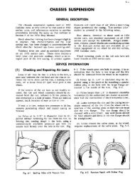
GENERAL DESCRIPTION<br />
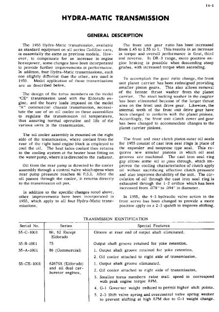
<strong>The</strong> 1955 Hydra -Matic transmission, available<br />
as standard equipment on all series Cadillac cars,<br />
is essentially the same as previous models. However,<br />
to compensate for an increase in engine<br />
horsepower, some changes have been incorporated<br />
to provide further improvements in performance.<br />
In addition, four Hydra-Matic transmissions, each<br />
one slightly different than the other, are used in<br />
1955. Model application of these transmissions<br />
are as described below.<br />
<strong>The</strong> design of the torus men<strong>The</strong>rs on the model<br />
"CE" transmission used with the Eldorado en<br />
gine, and the heavy loads imposed on the model<br />
"A" commercial chassis transmission, necessi<br />
tate the use of an oil cooler on these assemblies<br />
to regulate the transmission oil temperature,<br />
thus assuring normal operation and life of the<br />
various units in the transmission,<br />
<strong>The</strong> oil cooler assembly is mounted on the right<br />
side of the transmission, where coolant from the<br />
rear of the right hand engine block is employed to<br />
cool the oil. <strong>The</strong> heat laden coolant then returns<br />
to the cooling system at the heater hose fitting on<br />
the water pump, where it is directed to the radiator.<br />
Oil from the rear pump is directed to the cooler<br />
assembly through a control valve which opens when<br />
rear pump pressure reaches 60 P.S.!. After the<br />
oil passes through the cooler, it returns directly<br />
to the transmission oil pan.<br />
In addition to the specific changes noted above,<br />
other improvements have been incorporated in<br />
1955, which apply to all four Hydra-Matic trans<br />
missions,<br />
<strong>The</strong> front unit gear ratio has been increased<br />
from 1 .45 to 1 .55 to 1. This results in an increase<br />
in torque and overall performance in first, third<br />
and reverse. !n DR-3 range, more positive en<br />
gine braking is possible when descending steep<br />
grades, with increased torque when ascending.<br />
To accomplish the gear ratio change, the front<br />
unit planet carrier has been redesigned providing<br />
smaller pinion gears. This also allows removal<br />
of the bronze thrust washer from the planet<br />
carrier. <strong>The</strong> steel backing washer in the catyier<br />
has been eliminated because of the larger thrust<br />
area on the front unit drive gear. Likewise, the<br />
internal teeth of the front unit drive gear have<br />
been changed to conform with the planet pinions.<br />
Accordingly, the front unit clutch cover and gear<br />
has been changed to accommodate changes to the<br />
planet carrier pinions.<br />
<strong>The</strong> front and rear clutch piston outer oil seals<br />
for 1955 consist of cast iron seal rings in place of<br />
the expander and neoprene type seal. This re<br />
quires new annular pistons in which oil seal<br />
grooves are machined. <strong>The</strong> cast iron seal ring<br />
gap allows some oil in puss through, which im<br />
proves the cooling characteristics of clutch apply<br />
oil without sacrificing effective clutch pressure<br />
and also improves durability of the unit. <strong>The</strong> cir<br />
culation of oil through the cast iron seal ring is<br />
exhausted through the 1-2 orifice which has been<br />
increased from .078" to .094" in diameter.<br />
In 1955, the 4-3 hydraulic valve action in the<br />
front servo has been changed to provide a more<br />
positive apply on a 2-3 upshift to improve shifting.<br />
55-B-tool<br />
55-A-1001<br />
55-CE-tool<br />
6267SX ldorado<br />
and all dual car<br />
buretor engines.<br />
<strong>TRANSMISSION</strong> IDENTIFICATION<br />
Serial No. Series Special Features<br />
55-C-IOU 1<br />
60, 62 Except<br />
Eldorado<br />
75<br />
86 Commercial<br />
Groove at rear end of output shaft eliminated.<br />
Output shaft groove retained for yoke retention.<br />
1. Output shaft groove retained for yoke retention.<br />
2. Oil cooler attached to right side of transmission.<br />
1. Output shaft groove eliminated.<br />
2. Oil cooler attached to right side of transmission.<br />
3. Smaller torus members raise stall speed to correspond<br />
with peak engine torque RPM.<br />
4. G-l Governor weight reduced to permit higher shift points.<br />
5. 2-3 Shift valve spring and overcontrol valve spring weaker<br />
to prevent shifting at high RPM due to G-1 weight change.
14-2<br />
F-IYDRA-<strong>MATIC</strong><br />
<strong>TRANSMISSION</strong><br />
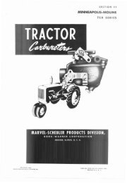
To make certain that the 4-3 valve is in the<br />
open unrestricted position on all 2-3 upshifts,<br />
Fig. 14-1, and in the closed restricted position,<br />
Fig. 14-2, for a114-3 downshifts in 1955, rear hand<br />
release oil is directed against the large end of the<br />
4-3 valve to close the 4-3 valve, whereas in 1954,<br />
G-1 oil was used. <strong>The</strong> rear band release oil is<br />
taken from a point in the rear servo body so that it<br />
becomes available only in 3rd and 4th speeds after<br />
the rear servo has completed its release stroke<br />
Fig. M-2 Servo Action During 4-3 Downshift<br />
Fig. 14-1 Servo Action During 2-3 Upshift<br />
rear clutch applied - hand released. This allows<br />
the front servo to complete its apply action on a 2-3<br />
upshift before the apply passage is closed re<br />
stricted. On a 4-3 downshift, front band apply oil<br />
is metered, allowing the front clutch sufficient<br />
time to release before the band is applied.<br />
Since C-i oil is not directed to the front servo<br />
in 1955, restricted front band apply oil is used in<br />
place of C-I oil in the overrun control valve. <strong>The</strong><br />
overrun control valve directs the restricted front<br />
band apply oil in 3rd speed, and compensator oil<br />
for 2nd and 4th speeds, to the compensator piston.<br />
By use of a stronger overrun control valve spring<br />
and restricted front band apply oil, the apply ac<br />
tion is smoother,<br />
To incorporate the changes in the front servo<br />
action, the front servo body has been redesigned,<br />
eliminating the C-I feed hole. <strong>The</strong> compensator<br />
feed hole is converted to an exhaust hole. A new<br />
feed hole in the front servo for the rear band re<br />
lease oil has been incorporated. <strong>The</strong> front servo<br />
valve body has been changed accordingly. In addi<br />
tion, the rear to front servo compensator pipe has<br />
been replaced with a new rear to front servo rear<br />
band release oil pipe.<br />
<strong>The</strong> rear servo body has been changed to pro<br />
vide a greater holding force, accommodating the<br />
new front unit gear ratio. To accomplish this, the<br />
effective length of the band actuating lever has<br />
been increased by relocating the clevis pin hole<br />
in the rear servo body. <strong>The</strong> rear band release oil<br />
feed hole in the rear servo is located just to the<br />
rear of the former 1954 compensator feed hole<br />
which has been eliminated in 1955. Fig. 14-3.<br />
Two rear servo retainer to accumulator body<br />
lock washers have been eliminated in 1955. Suffi<br />
cient locking action can be obtained by rear servo<br />
spring force against the retainer.<br />
<strong>The</strong> flywheel housing consists ofaone piece unit,<br />
whereas in 1954,thehousing consisted of two sepa<br />
rate pieces with a portion integral to the engine<br />
block. To accommodate this housing, the drain plug<br />
has been removed from the torus cover and installed<br />
at the outer edge of the front face of the flywheel.<br />
Flywheel to torus cover attaching screws are ac<br />
cessible from the front of the flywheel. Weld nuts<br />
have been installed on the back flange of the torus<br />
cover to engage flywheel bolts. A cover plate<br />
mounted at the lower, forward portion of the fly -<br />
wheel housing can be removed to permit access to<br />
the drain plug and attaching screws. This requires<br />
removal of the starter motor assetnbly.<br />
A new 1-2 shift valve spring is used in 1955 to<br />
improve shift "feel" by raising the part throttle<br />
1-2 shift point.<br />
<strong>The</strong> 3-4 regulator plug diameter has been en<br />
larged to provide a full throttle not through de<br />
tent 4-3 downshift speed of approximately 34<br />
M.P.H. as compared with approximately 27 M.P.FI.<br />
in 1954.<br />
<strong>The</strong> pressure regulator spring has been made<br />
stronger to provide an increase in line pressure.<br />
This necessitates a change in the regulator plug to<br />
accommodate the new spring.
=<br />
-<<br />
a<br />
3:<br />
> -I<br />
n<br />
-I<br />
><br />
z<br />
CO<br />
3:<br />
C’,<br />
U<br />
0<br />
z<br />
jiovLNtROL<br />
pEFRSE BOcKr<br />
MSTON<br />
GOVERNOR<br />
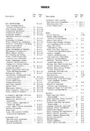
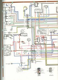
Fig. 14-3 Hydm-Motic Transmission Oil Circuit<br />
a
14-4<br />
<strong>HYDRA</strong>-<strong>MATIC</strong> <strong>TRANSMISSION</strong><br />
SERVICE<br />
INFORMATION<br />
With the exception of a few changes, the Service<br />
Information contained in the 1954 Shop <strong>Manual</strong> will<br />
be applicable to all 1955 Hydra-Matic Transmis<br />
sions. Make certain the following information is<br />
thoroughly reviewed before proceeding with any<br />
service work.<br />
1 Minor Changes<br />
a. Correction of Leaks at Fluid Coupling<br />
requires expanding the ring until free of piston<br />
groove. When installing the piston and ring as<br />
sembly, Tool No. J-5608 may be used to compress<br />
the seal ring until assembly is positioned in the<br />
clutch cover. Fig. 14-4.<br />
Ring compressor<br />
Tool i-5608<br />
Procedure for determining at which point leak<br />
age occurs will differ from 1954 because of the one<br />
piece flywheel housing used in 1955. Removal of<br />
the cover plate in front of the housing will permit<br />
checking for leaks at torus cover to flywheel bolts<br />
and at drain plug.<br />
b. Removal and Installation of Hydra-Matic<br />
Transmission<br />
<strong>The</strong> 1-lydra-Matic removal and installation pro<br />
cedure for 1955 is the same as in 1954 with the<br />
following exceptions:<br />
1. With a one piece flywheel housing, there will<br />
be no lower cover to remove.<br />
2. To reach the torus cover to flywheel mount<br />
ing bolts, remove starter motor and flywheel<br />
housing front cover.<br />
3. Drain the transmission, as described in<br />
Section 2, Note lOb.<br />
4. On transmissions equipped with oil cooler,<br />
hoses at cooler must first be removed and hose<br />
ends plugged to prevent coolant leakage and entry<br />
of dirt or other foreign matter. When removing<br />
oil pan, exercise caution when disconnecting the<br />
pump feed line from the cooler valve body in the<br />
oil pan.<br />
5. When installing transmission, observe changes<br />
noted above.<br />
c. Disassembly and Assembly of Transmission<br />
1. Planet <strong>Car</strong>rier - With smaller planet pinions,<br />
the bronze thrust washer inside the planet carrier<br />
can now be removed. Upon assembly, make cer<br />
tain washer is reinstalled.<br />
2. Front and Rear Unit Outer Clutch Piston<br />
Seals - <strong>The</strong> outer clutch piston seals in the front<br />
and rear units for 1955 are cast iron ring seals,<br />
whereas in 1954 the seals consisted of anexpander<br />
and rubber seal. Removal of the ring seal merely<br />
Fig. 14-4 Installing Clutch Piston Seal<br />
<strong>The</strong> front unit oil seal ring gap must be held to<br />
specification. This is required to allow for more<br />
tolerance of the front clutch drum bore. All mea<br />
surements must be taken with ring located squarely<br />
in clutch drum bore. To check ring gap, proceed<br />
as follows;<br />
a. Insert oil seal ring squarely in clutch drum<br />
assembly.<br />
b. Using a feeler gage, check the ring gap. <strong>The</strong><br />
ring gap limits are .OOl"-.OOô" measured at the<br />
OD of the ring.<br />
c. If gap is too tight, it may be filed to fall<br />
within limits.<br />
NOTE: <strong>Car</strong>e should be exercised not to<br />
file the ring gap so as to allow the OD to be<br />
longer than the ID. <strong>The</strong> maximum taper must<br />
be .007" gap at ID.<br />
3. CONTROL VALVE ASSEMBLY - Service op<br />
erations covering the control valve assembly re<br />
main the same as for 1954.<br />
2 Throttle Control Linkage<br />
Adjustment<br />
1. Remove transmission throttle control clevis<br />
pin, and check lever position with Tool No.
14-5<br />
<strong>HYDRA</strong>-<strong>MATIC</strong> <strong>TRANSMISSION</strong><br />
J-3065-C by fitting tool to rear face of transmis<br />
sion case and inserting clevis pin through lever<br />
and 49 E 50 hole in tool while lever is in its rear<br />
ward position. If throttle lever is misaligned,<br />
bring it into alignment by bending with Tool No.<br />
.1-3310.<br />
f Install spring and adjusting nut on front end<br />
of T.V. rod.<br />
g Adjust the nut until the distance between the<br />
front face of the trunnion and the rear face of the<br />
adjusting nut is 1-13/32". Fig. 14-5.<br />
2. Assemble linkage to transmission throttle<br />
lever and install new cotter pin.<br />
3. Remove spring clip from carburetor to dash<br />
relay rod trunnion and remove trunnion from re<br />
lay lever.<br />
4. Place 1/4 inch drill shank through gaginghole<br />
in dash relay lever and into dash relay bracket.<br />
5. With engine running, set throttle lever in<br />
hot idle position. Air Conditioner "off’<br />
6. Adjust carburetor to dash relay rod trunnion<br />
to allow free entry into dash relay lever.<br />
7. Install spring clip in trunnion.<br />
8. On cars with single carburetor<br />
a Back off both jam nuts on the T.V. rod at<br />
carburetor to allow free movement of rod in<br />
trunnion.<br />
b Push end of T.V. rod to position transmis<br />
sion throttle valve against its stops.<br />
c Bring rear jam nut up against trunnion and<br />
hack off S flats 1-1/3 turn.<br />
NOTE: This adjustment may be increased<br />
or decreased to improve shift characteristics<br />
after road test.<br />
d Tighten front jam nut. Check to make cer<br />
tain linkage moves freely.<br />
9. On cars with dual carburetors<br />
a Remove lock nut, adjusting nut and spring<br />
from forward end of T.V. rod.<br />
h Back off rear lock nut and adjusting nut on<br />
T.V. rod to permit free movement of rod in<br />
trunnion.<br />
c Push on end of T.V. rod to position trans<br />
mission throttle valve against its stop.<br />
d Bring rear adjusting nut up against trunnion<br />
and back off 3 complete turns.<br />
e Tighten rear lock nut.<br />
Fig. 14-5 T.V. Rod Adjustment - Eldorado Engine<br />
Ii Install<br />
justing nut.<br />
lock nut against front end T,V. ad<br />
10. Remove 1/4 inch drill shank from dash re<br />
lay and check position of accelerator pedal with<br />
wide open throttle. Pedal should touch floor mat<br />
with slight pressure allow 1/2" clearance if mat<br />
has been removed when throttle is wide open.<br />
11. Adjust accelerator pedal position at pedal<br />
end of dash relay to accelerator pedal rod.<br />
12. Road test car to insure proper shifting<br />
characteristics.<br />
3 Band Adlustments<br />
To adjust bands on transmissions equipped with<br />
oil cooler will require draining of oil at the oil<br />
pan drain plug, disconnecting oil lines at pan, and<br />
removal of the oil pan.<br />
NOTE: When removing oil pan, exercise<br />
caution when disconnecting the rear pump feed<br />
line from the cooler valve body in the oil pan.<br />
Make certain not to lose cooler valve and spring.<br />
Upon installation of oil pan, be certain that the
14-6<br />
<strong>HYDRA</strong>-<strong>MATIC</strong> rRANSMISSION<br />
rear pump feed line is properly installed into the<br />
oil pan ler valve body.<br />
4 Checking Pump Pressure<br />
‘<strong>The</strong> pump pressure can he checked with the<br />
transmission in the car, u.sing a gage calihrated<br />
to at lees’ 250 P.8.1.<br />
1. Remove band adjusting hole cover from floor<br />
pan, C lean dirt from op of ease, and remove plug<br />
from top of transmission ease betwcji band adlusting<br />
screws.<br />
2. Screw pressure gage line fitting into hole in<br />
ease with gage placed so it can be read from the<br />
drivers scat.<br />
3. Drive car until transmission oil has reached<br />
normal driving tcjnpsrature approximaLely 2151°P}.<br />
a, Drive Range Check<br />
If pressure readings are below the specified<br />
amount for any ns the aho’ie tests a malfunctionlog<br />
pressure regulator or a leak In the system is<br />
indicated.<br />
5 Removal and Installation of Oil<br />
Cooler Assembly<br />
a. Removal and ln.tnllotian of<br />
Coaler Ass.mbly Only<br />
I. Disconnect coolant hoses st cooler and pLug<br />
open ends to prcvent coolant leflage and eny of<br />
dirt or oriler foreign materiaL.<br />
2. scoooect two oil lines at cler.<br />
3. Renve screws retoining cooler<br />
end case and relliove cooler.<br />
4. To iostsll. reverse procethire<br />
afeve.<br />
to oil pan<br />
descrihed<br />
<strong>The</strong> following tests may be nude, by road teat<br />
or wIth car on jack stands -<br />
1. it 400 RPM, the prcauro slauld be 50 PSI.<br />
minimum in a LI range.s except reverse which<br />
could be higher.<br />
2. Zero throttle pressure - At 35 MPH in fourth<br />
gear with acre throttle, line pressure should be<br />
73 in I I PSI.<br />
3. Foil throLtle pressure road tat - l’u II<br />
throttic pressure in 6,orth gear at 35 MPH full<br />
throttle tIiout wing through detent should be<br />
114 - 122 P.5.1.<br />
4. To chock rho operauon ol the rear pump<br />
alone, drive the car at 40 to 45 Mlii In fourth<br />
speed. <strong>The</strong>n shift to neutral and tori’ 611 he igni<br />
Ein!l. Pressure should be at least 70 P.S.<br />
Low rear pump oil pre.sure should he currecred<br />
by replacement of rite pump gvors or by<br />
checking for icakasic in ooier unIts -<br />
b. Revuts. Pe..ure Check<br />
- Place the selector lever in reverse pesition<br />
and note pressure with engine ruiming at 4i10 RPM.<br />
This reading should he as high or higher than rile<br />
previous pressure checks in drive range.<br />
2. With the selector lever in reverse, apply the<br />
foot hra}e and Increase engine spcd io half<br />
throttle. Pressure should increase to 176 PSI.<br />
minimum. <strong>The</strong> pressure range ander the above<br />
conditions Is 176 PSI, minimum.<br />
g. 14-6 Oil Cnol a, hose and Pipe Coo ,wcfio,<br />
b. Removal and Inslollasian of Oil Pan<br />
Equipped with Cooler Assembly<br />
NOTE This operation is required when ad<br />
justing hands or disassembling transmission.<br />
1. Dr a in oiL :r 010 ra nsmissioo at oil pan drain<br />
plug<br />
NOTE: Fluid coupling riced not be drained<br />
ror tl,s operation.<br />
2. Disconnect oil lines ot oil pan<br />
3. Remove oil pan making certain not to bend or<br />
distort rhe rear pump to cooler vaive body faed<br />
NOTE: 1ien cii pan has been removed. In<br />
cam ealvc and spring in cooker valve bioy to<br />
make certain parts are nor lost in removal.
14-7<br />
<strong>HYDRA</strong>-<strong>MATIC</strong> <strong>TRANSMISSION</strong><br />
4. If it is necessary to replace cooler, discon- 8. Remove steering column lower cover.<br />
nect hoses and remove cooler. Make certain hoses<br />
are plugged to prevent leakage of coolant. 9. Remove Hydra-Matic dial pointer.<br />
5. Inspect all parts for evidence of wear, dam<br />
age and foreign material. Clean and replace parts<br />
if necessary.<br />
10. Remove directional signal switch.<br />
11. Remove screws holding upper bearing re<br />
tainer to steering jacket.<br />
6. To install oil pan, reverse procedure de<br />
scribed above, making certain rear pump feed 12. Remove cotter key, dust shield and horseline<br />
is positioned properly in the cooler valve shoe retainer at lower shift lever on steering tube<br />
body,<br />
and then disengage shift lever from shifter tube.<br />
13. Pull shifter tube up out of the steering jacket<br />
6 Towing Instructions<br />
and then unscrew hearing retainer from shifter<br />
tube.<br />
Cadillac cars equipped with Hydra-Matic trans<br />
mission should NEVER be towed unless the pro-<br />
14. To install, reverse above procedure.<br />
peller shaft is disconnected, or the rear wheels<br />
are raised off the ground. This is necessary be<br />
cause of possible close production limits which h. Removal and Installation of Lower<br />
might cause the front clutch to drag and possibly Shifter Lever<br />
burn up.<br />
1. Remove steering column assembly from car<br />
<strong>The</strong> only exception to this rule would be in a as described in Section 7, Note 11.<br />
situation where pushing would be for only one or<br />
two blocks maximum, transmission oil cold, for 2. Remove horn button and spring.<br />
purposes of getting the car started. Speeds of 20<br />
-25 MPH must be maintained to insure proper lub- 3. Remove steering wheel hub nut.<br />
rication.<br />
4. Remove steering wheel and spring.<br />
7 Removal and Installation of Shifter<br />
5. Loosen lower steering column clamp and re<br />
Tube and Lower Shift Lever<br />
move steering clamp and remove steering shaft<br />
and lower bearing.<br />
a. Removal and Installation of Shifter lube<br />
<strong>The</strong> following procedure relates specifically to<br />
removal of shifter tube from car without removal<br />
of steering colunm assembly.<br />
1. Disconnect battery.<br />
2. Remove neutral safety switch and horn con<br />
tact from lower steering column.<br />
6. Remove directional signal switch.<br />
7. Remove selector lever and anti-rattle spring.<br />
8. Remove screws holding upper bearing re<br />
tamer to steering jacket.<br />
9. Remove cotter key, dust shield and horse<br />
shoe retainer at lower shift lever on steering tube.<br />
3. Remove horn button and spring.<br />
10. Disengage shift lever from shifter tube<br />
4. Remove steering wheel hub nut, and remove tube.<br />
5. Remove horn ring retainer and horn ring. 11. Remove lower shift lever,<br />
6. Remove steering wheel using special puller, 12. Remove upper bearing retainer.<br />
Tool No. J-1859.<br />
13. Press upper bearing from retainer.<br />
7. Remove steering shaft tensioner spring and<br />
split ring.<br />
14. To install, reverse above procedure.
"10"50.0<br />
."510.0<br />
"50.0<br />
<strong>HYDRA</strong>-<strong>MATIC</strong> <strong>TRANSMISSION</strong><br />
Subject and Remarks<br />
SPECIFICATIONS<br />
FLYWHEEL COVER AND TORUS ASSEMBLIES<br />
Flywheel Cover, maximum runout of hub<br />
Backlash between splines of cover and front unit drive gear<br />
Torus members, maximum runout of face<br />
Drive Gear backlash between gear and planetary pinions<br />
Planet <strong>Car</strong>rier Pinions, end play<br />
GOVERNOR ASSEMBLY<br />
Maximum runout of governor sleeve<br />
Maximum runout of governor drive flange face.<br />
REAR OIL PUMP<br />
End play of gears<br />
Backlash of gears<br />
Mainshaft, end play<br />
REVERSE ASSEMBLY<br />
End play of planet carrier pinions<br />
Backlash of internal gear pinions.<br />
OUTPUT SHAFT ASSEMBLY<br />
Backlash of pinions - Internal Gear<br />
Sun Gear.<br />
End Play of Pinions<br />
All Series<br />
to 0004"<br />
. 0005" to 0008"<br />
to 0.026"<br />
0 002"<br />
0001" to 0004"<br />
0.006" to 0010"<br />
0.004" to 0.018"<br />
0.005" to 0.026"<br />
0.008" to 0.012"<br />
0.0006" to 0.0008"<br />
0 0003" to 0 0005"<br />
0.005" to 0.026"<br />
Application<br />
TORQUE TIGHTNESS<br />
Band adjusting screw lock nut 1/2-20<br />
Extension housing to case 3/8-16<br />
Extension housing to reverse unit support 3/8-16<br />
Flywheel to crankshaft 7/16-20<br />
Front cover retaining screws 5/16-18<br />
Front oil pump cover to body 1/4-20<br />
Front servo assembly<br />
1/4 pipe<br />
Front servo body to cylinder 1/4-20<br />
Front servo to case 3/8-16<br />
Governor body to drive flange 1/4-20<br />
Governor bushing retainer to governor body 10-24<br />
Internal gear to rear drum 10-24<br />
Lever, shift on transmission 3/16-24<br />
Mainshaft, retaining nut 7/8-16<br />
<strong>Manual</strong> lever clamp screw 5/16-24<br />
Oil pan tO case 5/16-18<br />
Oil pan drain plug 5/8-18<br />
Oil pressure take-off at case 1/8 pipe<br />
Outer valve body to inner body 10-24<br />
Pressure regulator valve plug 1-1/16-16<br />
Rear oil pump to case 5/16-18<br />
Rear pump cover to body 1/4-20<br />
Rear servo to case 3/8-16<br />
Reverse unit drive flange to rear unit drum 5/16-18<br />
Shifter bracket to case 5/16-18<br />
Side cover to case 1/4-20<br />
Throttle lever clamp screw 1/4-28<br />
Flywheel to Torus cover 3/8-24<br />
Torus cover drain plug<br />
1/8 pipe<br />
Valve body to case 1/4-20<br />
Size<br />
Ft. Lbs.<br />
Mm.<br />
40<br />
28<br />
28<br />
80<br />
10<br />
12<br />
6<br />
6<br />
23<br />
6<br />
3<br />
3<br />
18<br />
30<br />
10<br />
10<br />
35<br />
15<br />
3<br />
40<br />
15<br />
6<br />
23<br />
10<br />
15<br />
10<br />
10<br />
40<br />
6<br />
6<br />
Ft. Lbs.<br />
Max.<br />
50<br />
33<br />
33<br />
85<br />
13<br />
15<br />
7<br />
8<br />
28<br />
8<br />
4<br />
4<br />
22<br />
35<br />
13<br />
13<br />
45<br />
18<br />
4<br />
50<br />
18<br />
8<br />
28<br />
13<br />
18<br />
12<br />
12<br />
45<br />
7<br />
8
14-9<br />
<strong>HYDRA</strong>-<strong>MATIC</strong> <strong>TRANSMISSION</strong><br />
C<br />
E<br />
F<br />
G<br />
6<br />
VS<br />
R<br />
J<br />
M<br />
N<br />
P<br />
a<br />
I V W X Y<br />
Li<br />
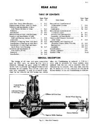
Fig. 14-7 Special Tools<br />
KEY TOOL NO. NAME KEY TOOL NO. NAME<br />
A<br />
B<br />
C<br />
D<br />
E<br />
F<br />
G<br />
H<br />
I<br />
J<br />
K<br />
L<br />
M<br />
J-26 19-A<br />
J-2623<br />
J-2540-A<br />
1459-A<br />
J-4670-B<br />
J-2174<br />
J-3310<br />
J-4353<br />
J-2187<br />
J-1537<br />
J-5071<br />
J-1693-A<br />
J-3065-C<br />
Slide Hammer<br />
Ext. Housing Oil Seal Remover<br />
Collet<br />
Pressure Checking Gauge<br />
Drum Holder<br />
Clutch Spring Compressor<br />
Rear Clutch Hub Retainer<br />
Bracket<br />
Throttle Lever Bending Tool<br />
Clutch Piston Actuator and Blow<br />
Gun<br />
Front Planet <strong>Car</strong>rier Assembly<br />
Holder<br />
Oil Delivery Sleeve Ring Com<br />
pressor<br />
Rear Servo Gauge<br />
Front Servo Gauge<br />
Throttle Lever Checking Gauge<br />
N<br />
0<br />
P<br />
Q<br />
R<br />
S<br />
T<br />
U<br />
V<br />
w<br />
x<br />
Y<br />
-2170<br />
J-2587-B<br />
J-2184-A<br />
J- 1537<br />
KMO-3kJ<br />
J-1465-A<br />
J-4731<br />
-4752<br />
J-5l57<br />
J-5586<br />
J-2182<br />
J-l942-A<br />
Front Pump<br />
staller<br />
Cover Oil Seal In<br />
Transmission Mainshaft End<br />
Play Gauge<br />
Front Pump Holder and Socket<br />
Set<br />
Oil Delivery Sleeve Ring Com<br />
pressor<br />
Dial Indicator Set<br />
Mainshaft End Play Dial Indi<br />
cator Extension Rod<br />
Governor to Sleeve Aligning<br />
Tool<br />
Piston to Drum Installing Tool<br />
Regulator End Casting Assem<br />
bly Clamp<br />
Snap Ring Pliers<br />
Transmission Bearing Retainer<br />
Remover<br />
Extension Rear Oil Seal Installer
14-10<br />
<strong>HYDRA</strong>-<strong>MATIC</strong> <strong>TRANSMISSION</strong><br />
OTHER NOTES AND REFERENCES