pdf version - The Old Car Manual Project
pdf version - The Old Car Manual Project
pdf version - The Old Car Manual Project

You also want an ePaper? Increase the reach of your titles
YUMPU automatically turns print PDFs into web optimized ePapers that Google loves.
6-1<br />
CHASSIS SUSPENSION<br />
TABLE OF<br />
CONTENTS<br />
Note Name<br />
Front Wheel Alignment .<br />
Checking Tire Pressure<br />
Wheel Bearing Adjustment<br />
Wheel Run - Out and Eccentricity<br />
Balancing Wheels and Tires<br />
Static Balance<br />
Correction of Static Unbalance<br />
Dynamic Balance<br />
Checking Spring Heights<br />
Front Springs<br />
Rear Springs<br />
Wheel Alignment Measuring Methods.<br />
Caster Adjustment<br />
Camber Adjustment<br />
Toe In Adjustment<br />
Excessive Tire Wear -<br />
Causes and Corrections<br />
Improper Tire Inflation<br />
Wear Caused by Owner Driving<br />
Habits<br />
Front End Looseness or Camber<br />
Adjustment<br />
Toe-In and Toe-Out Adjustment<br />
High Temperature, Heavy Loads,<br />
Types of Roads<br />
Interchanging Tires<br />
Testing for Tire Noise<br />
Riding Complaints<br />
Removal and Installation of Wheel<br />
Shields<br />
Removal and Installation of Front<br />
Wheel, Flub, and Bearings<br />
Removal<br />
Installation<br />
Cleaning White Sidewall Tires .<br />
Removal and Installation of Front<br />
Shock Absorbers<br />
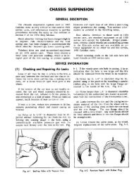
All 1954 series Cadillac cars utilize the indepen<br />
dently sprung front wheel suspension system. This<br />
design permits either front wheel to follow the<br />
irregularties of the road without appreciably af<br />
fecting the other front wheel or transferring road<br />
shocks to the steering system.<br />
<strong>The</strong> front wheels are controlled in their up and<br />
down movement by coil springs and direct acting,<br />
permanently sealed shock absorbers. <strong>The</strong> springs<br />
are insulated at the upper and lower ends by rubber<br />
insulators, which prevent metal to metal contact of<br />
the spring with the frame and the resultant trans<br />
fer of noise, due to spring movement, to the frame.<br />
<strong>The</strong> shock absorbers are located in the center of<br />
the coil springs and are attached, at the upper end,<br />
Note Page<br />
No. No. Note Name<br />
1 6-3 Removal<br />
2 6-3 Installation<br />
3 6-3 Removal and Installation of Front<br />
4 6-3 Stabilizer<br />
5 6-4 Removal<br />
Sa 6-4 Installation<br />
Sb 6-4 Removal and Installation of Steering<br />
5c 6-5 Knuckle<br />
6 6-5 Removal<br />
6a 6-5 Installation<br />
6b 6-5 Removal and installation of Steering<br />
7 6-6 Knuckle Support<br />
8 6-7 Removal<br />
9 6-7 Installation<br />
10 6-7 Removal and Installation of Upper<br />
Suspension Arm<br />
11 6-8 Removal<br />
1 la 6-8 Installation<br />
Removal and Installation of Lower<br />
lib 6-8 Suspension Arm and Front Spring<br />
Removal<br />
1k 6-9 Installation<br />
lId 6-9<br />
Straightening Bent Parts<br />
Removal and Installation of Rear<br />
.<br />
lie 6-9 Shock Absorbers<br />
12 6-10 Removal and Installation of Rear<br />
13 6-10 Wheel and Brake Drum<br />
14 6-10 Removal<br />
installation<br />
15 6-11 Servicing Rear Spring Liners<br />
Removal and installation of Rear<br />
16 6-11 Spring<br />
16a 6-li Diagnosis Chart<br />
i6b 6-11 Torque Tightness<br />
17 6-11 Specifications<br />
Special Tools<br />
18 6-12<br />
GENERAL DESCRIPTION<br />
Note<br />
No.<br />
Page<br />
No.<br />
18a 6-12<br />
18b 6-12<br />
19 6-12<br />
19a 6-12<br />
l9b 6-12<br />
20 6-13<br />
20a 6-13<br />
20b 6-13<br />
21 6-13<br />
2la 6-13<br />
21b 6-13<br />
22 6-14<br />
22a 6-14<br />
22b 6-14<br />
23<br />
23a<br />
23b<br />
24<br />
6-14<br />
6- i4<br />
6-15<br />
6-15<br />
25 6-16<br />
26<br />
26a<br />
26b<br />
27<br />
6-16<br />
6-16<br />
6-17<br />
6-17<br />
28 6-17<br />
6-18<br />
6-20<br />
6-21<br />
6-22<br />
to the spring seat tower and, at the lower end to<br />
the spring seat in the lower control arm.<br />
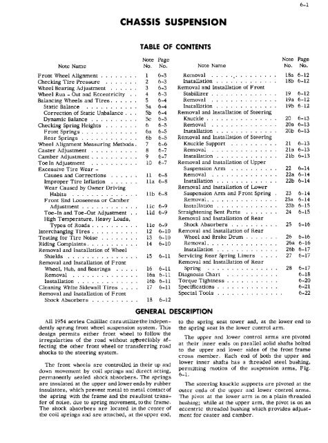
<strong>The</strong> upper and lower control arms are pivoted<br />
at their inner ends on parallel solid shafts bolted<br />
to the upper and lower sides of the front frame<br />
cross member. Each end of both the upper and<br />
lower inner shafts has a threaded steel bushing,<br />
permitting motion of the suspension arms, Fig.<br />
6-i.<br />
<strong>The</strong> steering knuckle supports are pivoted at the<br />
outer ends of the upper and lower control arms.<br />
<strong>The</strong> pivot at the lower arm is on a plain threaded<br />
bushing; while at the upper arm, the pivot is on an<br />
eccentric threaded bushing which provides adjust<br />
ment for caster and camber.
CHASSIS SUSPENSION<br />
W n<br />
D-<br />
0..-u N.<br />
1<br />
F<br />
h<br />
5o.<br />
FIFFI.0<br />
SFr :i,!<br />
- Spite<br />
cap----<br />
-_-<br />
ls±ig<br />
.O*!<br />
F i . 6-I RaF,P S,apen;ioi - Di e n’S led<br />
Synthetic rubber seals are used 0 pi*otect all<br />
hu phi Figs against road dirt and other foreign<br />
materasi. A rubber hamper on the lower $u5pen<br />
sion arm is agal 0 cushioti the extreme traieI of<br />
the upper and lower suspension arms.<br />
<strong>The</strong> steering knuckle i meuntei an the steering<br />
knuickje supporl out a harnened steel ntuckk pin<br />
king phi whic.h rotates in bronze bushings in the<br />
upper and lower part of the steering knuckle- <strong>The</strong><br />
vertical thrust is taken by a bearing located<br />
between the lower face of the knuckle aupport and<br />
the steering knuckle.<br />
A front end stebi Flier bar Is used in connection<br />
with the independent suspension system to provide<br />
steering stability and to control body roll. <strong>The</strong><br />
stabilizer bar Is 1nounted ahead of the suspension<br />
arms, on the frame side bars and is comacted to<br />
the coil spring seats on the lower control arms<br />
by steel links which are completely cushioned ci<br />
ssch end by rubber bushings.<br />
<strong>The</strong> direct acting type rear shock absorbers<br />
are secured at the bottom by anchor bolts ii, flue<br />
rear gpring bolt plates and at he top through<br />
brackets we!ded to the rear intermediate frame<br />
memher. This !ses_heg type of mounting<br />
of ±e rear shock absorbers gives them tho double<br />
function of rnhth; LLng trauFeocrec roll sod oheorhing<br />
road shocks.<br />
<strong>The</strong> rear springs are of rite seuniU1pticah leaf<br />
type with waxed lull length lioersbetween the leaves<br />
to provide the correct Interleaf friction and prevent<br />
squeaking throughout the life of the springs. <strong>The</strong><br />
springs are cushioned at each end by rubber bush<br />
ings and at the spring seat on the axle housing by<br />
a rubber Insulating psi.<br />
<strong>The</strong> wheels oil 1934 -62 stud 605 are i3 inches in<br />
diameter, with 6-inch rims, and use 8.00 x LS-4<br />
pty black titee. optional with &20 x 15 white wnll<br />
tires. <strong>The</strong> 1954-75 wheels are 15 inches iii dia<br />
meter and use 5.20 156 Ply tires. All riffle are<br />
of the drop center type. Wheels on the 1954-73<br />
ami 86 cars are the came as on 60 and 62 Series<br />
except for heavier stock thickness and may be<br />
identified by a 3/16" hole in the spider of the wheel,<br />
Al so. a letter is stamped on the out side of the<br />
rim adjacent to the verve stem hole- Wire wheele<br />
are standard equipment on Eldorado Style civertible<br />
ctiupes and are available as an accessory for<br />
all 62 and 605 series cars. Wire wheels are not<br />
recommended for installation on 75 sii 86 series.
6-3<br />
CHASSIS<br />
SUSPENSION<br />
1 Front Wheel Alignment<br />
Procedure<br />
SERVICE<br />
Correct wheel alignment is necessary to keep<br />
the front wheels in the true running position and is<br />
essential for easy steering. Tire wear is affected,<br />
as far as front end alignment is concerned, only<br />
by incorrect toe-in. Caster or camber does not<br />
affect tire wear.<br />
INFORMATION<br />
Tires should not be inflated to lower pressures in<br />
summer or bled to compensate for the increase in<br />
pressure due to heat. <strong>The</strong> recommended pressures<br />
are minimum pressures when the tires are cold for<br />
normal driving.<br />
For sustained speeds above 75miles per hour,<br />
tire pressure should be increased four pounds over<br />
specifications when checked cold.<br />
<strong>The</strong> following operations should be performed<br />
in the order listed whenever the front wheel align<br />
ment is checked and adjusted:<br />
Check tire pressure Note 2<br />
Check adjustment of front wheel bearings Note<br />
3<br />
Check trueness and tracking of front and rear<br />
wheels Notes 4 and 5.<br />
Check spring heights Note 6, a and b.<br />
Check condition<br />
of all bushings and bearings.<br />
Check for looseness in steering gear and con<br />
nections.<br />
Check caster and camber angle.<br />
Check toe-in and straight ahead position of steer<br />
ing wheel.<br />
2 Checking Tire Pressure<br />
Checking and inflating tires to the proper pres<br />
sure is the first step when performing any wheel<br />
alignment job. Correct tirepressuresareessential<br />
for securing correct measurements of other align<br />
ment factors, Following are the recommended tire<br />
pressures for 1954 series cars:<br />
62, 60S - 24 lbs. front and rear.<br />
75 - 28 lbs. front and rear,<br />
86 - 24 lbs. front,<br />
- 30 lbs. rear.<br />
It is recommended that tires be checked and<br />
inflated at least once a month including the spare<br />
tire.<br />
Tire pressure should always be checked when<br />
the tires are cold, preferabley in the morning or<br />
after standing in a cool place, and never after a<br />
high speed trip, Heat developed on fast runs or<br />
from hot pavements increases the pressures and<br />
they decrease again when the tires cool.<br />
When checking tires, the valve stem caps should<br />
be reinstalled, <strong>The</strong>se caps provide an essential fun<br />
ction in keeping dirt out of the valves, and in re<br />
ducing the possibility of slow leaks.<br />
3 Wheel Bearing Adjustment<br />
In adjusting the front wheel bearings, first make<br />
sure that the wheel is all the way on the spindle.<br />
Tighten the adjusting nut to 16 to 17 ft. lbs. torque<br />
to be sure all parts are properly seated and the<br />
threads are free, then back off nut and retighten to<br />
approximately 4 ft. lbs. torque. If the cotter key<br />
cannot be installed in this position, loosen the ad<br />
justing nut until it can be installed.<br />
CAUTION: When adjusting the front wheel<br />
bearings, care should be taken not to mistake<br />
play in the knuckle pin bushings for play in<br />
the wheel bearings.<br />
<strong>The</strong> rear wheel bearings on all series cars are of<br />
the sealed type and require no adjustmentorlubri<br />
cation.<br />
4 Wheel Runout and Eccentricity<br />
Lateral runout of a wheel and tire together<br />
should not exceed 1/16", the lateral runout of the<br />
disc wheel, as measured on the side of the rim at<br />
the base of the tire, should not exceed 3/64".<br />
Radial runout, or eccentricity, of the disc wheel<br />
and tire together or disc wheel alone should not<br />
exceed 3/64". Eccentricity of the wheel should be<br />
measured on the tire bead seat of the rim with the<br />
tire removed. Both lateral and radial runout of the<br />
wheel and tire may he minimized hy changing the<br />
tire location on the wheel until the least amount of<br />
runout is obtained.<br />
Runout specifications for both wire and disc<br />
wheels are the same, However, wire wheels may<br />
become distorted if subjected to ahuse by sharply<br />
hitting curbs when parking or by hitting chuck holes<br />
in the road at higher rates of speed. This can distort<br />
wire wheels to such an extent that serious vibration<br />
would result,
I<br />
-<br />
CHASSIS SUSPENSION<br />
S a I<br />
di to lot<br />
Bend<br />
a]<br />
+ ladde of Wheel<br />
Fslloe<br />
5 Balancing Wheels and Tires<br />
A wheel and tire essentbly may lose its original<br />
haitnes due to irregular ]rcau wear. tows or tire<br />
repair. nr toe-: :i !msaiiglo]nct:. Consequently, ii<br />
front end instability i:evelnps. the t.re anti wheel<br />
assembly should he checked for auth a:atic end<br />
dynamic balance in addition to steering gear<br />
adJtlstmen]. <strong>The</strong> aasemiiy should also he checked<br />
ror balance itlienevet tires are replaced, aid ccpcciaily<br />
hI c.asea tt::ete noneto’:da ye tit cquinicer,<br />
suer: da pu]]ctrc prxtf tubes nr heavier ely<br />
casIngs. are installed<br />
n<br />
Static Bolonce Stationary BoIancs<br />
;,g. 6-2 Nratsemenf of Dial ,diea]a]a<br />
Wire whee> may lx! checked on a fixtute<br />
na lint, and drum mounted On aspindle. <strong>The</strong> wheeJ<br />
mnunti tg face or !he fixture ho ti id he exactly at<br />
right ant: tea on rho ax ic of rotation slId tI]e mu an ting<br />
studs should be equidisosot frnm ftar axis.<br />
Cllo!ck flnuut with dial i itdicators plsr.ed Ott beth<br />
head seats and nga inst rhe 1:15 i ole face of the 00 tC<br />
fsiox hai:d, Fig 6-3. Mark tI:c outside of the rim<br />
at the point or greatest racial rtl:tOUt. Install tire<br />
un wheel en rha t lint of greatest no ijout of the tire<br />
and wheel assembly is t]pposite the point of maidmull]<br />
runuat of the wheel<br />
*Iliis is tue equal distrihutio’, a fweigit] of the<br />
whecl and tire assembly aadu: the axis of rotation<br />
so tOs I :Ijc seo ]nul ha a iw tetuien cv to r Irate b<br />
itself. diane i]]lbalance catises the poundi:ig aooiua<br />
on the front wheels tljat is caitcu hramp.<br />
b. Correction of Static Unbolonce<br />
Special Equipment Not Avaltoble<br />
I. fte’nave wl:’ccl and hub from spindle as stlnit.<br />
2. Clean sll grease from *,vJ:esi bearings aid<br />
races.<br />
3. Clomp a clean spindle in a hench SOSC, at if<br />
spindle on car must hr. used, clean it csrealiY -<br />
4. Muon wheel on spi ]]ffle and au us hc!a r :1<br />
loosely so that w lied is j tist hsld in posit’ 0]! aid<br />
is practically frictioni 85.<br />
5. Make .s are liar ire is infia ted to currcc<br />
pressure.<br />
6 Star: wheel in mntine and allow it to etnp by<br />
itself. If it continually stops in tue su]ne ptlsitinn,<br />
the hsavvsidc willisi at the Lnttomand the aseeo1hiv<br />
is nor in static balance.<br />
7. Mark heaviest 1xiint and aldo uppcr-]:lus], Or<br />
lightest point.<br />
8, Ina:all a weight at ligl:tes: point .ui the inside<br />
fellow hand of the wheel1 elte Li wilt compensate<br />
for tIle out of balance condition<br />
NOTE; If only a very slight unbalance is<br />
indicated. I may be necessary to nsa ohs tnt low -<br />
ing prnocdcre to ubtain correct balance, in -<br />
stalling the smallest weights avrlahle .. Avoid<br />
langing_on’1 mar35 aeijzht.e than arc necessary.<br />
I<br />
a tnstall two balanclnweights nfl inside of rim<br />
opposite each uther and 90 away fret:, the ighr and<br />
heavy p,fnts.<br />
Hg. 6-3 checktg sutaut<br />
h Movo these weights equally toward light side<br />
until wheel is in halsoce
6-5<br />
CHASSIS<br />
SUSPENSION<br />
9. Repack wheel bca ring with gruase install<br />
wheel, at,d adjust bearing us explained in Note 3.<br />
Dynamic Balance Running Balance<br />
Dynamic bait nec requires nor only that the sited<br />
ho La sLatic balance, hut aistu Lhat it run smoothly at<br />
all speeds on an axis which round Lhrnugtu t:-:e- cc liter<br />
of the wheel spindle. Dvnaur1ic unbalance sers up<br />
forces which cause Ll]e wneel to wubbie" Or<br />
shimnty".<br />
<strong>The</strong> quickest ann heat methods ur tesLtflg and<br />
correcting dynamic unbalance are by use of the pre -<br />
cision balancing equipment. pollnw equiptttent ntan<br />
ufacturerha instruction for correcL jtlacen,ent of<br />
balancIng weights. <strong>The</strong> best balancing is done with<br />
t]:e least amnt:nt or weight..<br />
6 Checking Spring Heights<br />
Fig1 6-4<br />
MeaiuiEng Front STini F-eig.il<br />
Before checking spring height, he sure that trunk L/ bolt to a hole in the frame aide her direc:iy<br />
is cmp and that Lttere is a fbi tank of gas, as all above the !tJ! bait Fig. 6-3 .‘Tho rear spritig height<br />
alignment specaficatanne are based on curb weight. shouie he equal *itl:i:u i/Il ml bath sides af car.<br />
Numiajize eirinn of the apritags by working the<br />
bumper tug and dawn and release slowly ,pe rntirting<br />
the eat tu assume 1:5 normal position.<br />
NOTE: New springs settle considerably dLtr -<br />
1mg the firat 2 ,Oho miles and therefore tile springs<br />
shuuid non ac replaced due to excessive hefght<br />
hefora this tUlle.<br />
a. Front Spring’<br />
Measure the distance from tilt: l° uuf the lower<br />
LonLruI arm to the center of the rubber banicer<br />
bracket front Inwe r rivet on the fret ito Fog - 6-4.<br />
Die spring height ahautd he eqt]al on both sides<br />
of the car within 3/3 ‘I, If heights are unoqual , the<br />
tow aide may he adjusted b Lhe addition oi shims,<br />
available from the Factory Parts Depa rttncat, be -<br />
tweel, the bottnm of the spri:tg and the spring seat<br />
on the lower suspension arm.<br />
b. Rear Springs<br />
Measure the distance tro]n the top of tuto spring<br />
Fig. 6-5 Meorering Rear Spring beigi<br />
DIe spriuug hteighLe should he:<br />
Model<br />
Weight*<br />
Frunt Spring<br />
Rear Sprit3g<br />
Front Rear height in Inches<br />
Height in Inches<br />
6019<br />
623:<br />
62371<br />
6267<br />
6219<br />
7523-38<br />
86 Comm. apprlux.<br />
1455<br />
23l<br />
2410<br />
2 11<br />
2 390<br />
2700<br />
2551<br />
2250<br />
lUu<br />
1215<br />
2335<br />
llml<br />
2500<br />
3040<br />
4-1/2<br />
4-1/2<br />
4-1/2<br />
4-1/2<br />
4-i/’2<br />
5- 3/i<br />
5_i<br />
tu 5-1/4<br />
to 5-1/4<br />
to -i/ 4<br />
to 5-1/4<br />
to 5-1/4<br />
to 6’ 1/8<br />
to 6-1/4<br />
4 to 9-1/2<br />
ro 9-1/2<br />
5-3/4 tO a -f/I<br />
S -3/4 ra 9-i/I<br />
S -3/4 0 9-1/2<br />
11 tnt 113-3/4<br />
9 3/3 ta lb-I/S<br />
a<strong>Car</strong> weight with tail tank of gasoline, hearer, radio, and wheel discs.
6-6<br />
CHASSIS<br />
SUSPENSION<br />
Positive Caster Angle Negative Caster Angle<br />
C/L of<br />
Knuckle Pin<br />
Vertical<br />
Positive Camber<br />
C/I of Wheel<br />
Front<br />
Knuckle<br />
Pin Angle<br />
Front Wheel Caster<br />
Front Wheel Camber<br />
This position for caster,<br />
camber and knuckle<br />
pin angle<br />
This position for<br />
toe-in and toe-out<br />
on turns<br />
Fig. 6-6<br />
7 Wheel Alignment Measuring<br />
Methods<br />
All wheel alignment equipment manufacturers<br />
provide detailed instructions for checking equip<br />
mdnt accuracy and measurement of alignment<br />
factors that should be followed exactly.<br />
In addition to the manufacturers instructions,<br />
be sure to observe the following general recom<br />
mendations:<br />
1. Check to see that there is no excess weight<br />
in the car.<br />
2. Align the car on the moveable plates of the<br />
alignment machine carefully so that the wheels<br />
are in the center of the plates. In addition, the car<br />
should be square with the plates.<br />
3. Inflate tires to proper pressure.<br />
4. Block both rear wheels, in addition to setting<br />
the hand brake, to prevent any slight movement<br />
of the car.<br />
Run-Out Location<br />
Elements of Front Wheel Alignment<br />
5. Raise the front end and check the runout on<br />
the outer surface of the tire. Mark the spot where<br />
maximum runout occurs.<br />
6. Place the maximum runout either to the front<br />
or rear as shown in Fig. 6-6. This neutralizes<br />
the effect of runout on caster or camber. Lower<br />
the wheels.<br />
7. Normalize the position of front spring by<br />
working the bumper up and down to get normal<br />
height of front spring.<br />
8. Caster and camber may now be checked.<br />
9. Raise front wheels and set maximum runout<br />
at top or bottom to neutralize effect on toe-in and<br />
toe-out. Fig. 6-6.<br />
10. Lower car, normalize springs and check<br />
toe-in.<br />
11. If any of the measurements are beyond the<br />
recommended limits, make the necessary adjust<br />
ments as outlined in Notes 8, 9, and 10.
CHASSIS SUSPENSION<br />
8 Caster Adjustment<br />
h.oosLon clamp screw CL upper et]c. of ste::rillg<br />
k,tuckie eupporL.<br />
2. Turit eccentric hushing with Caster andCaoi -<br />
her Adjusting Tuof No. j-5343 tti cumpiete turns<br />
only until correct caster angle is tthtained Fig.<br />
-<br />
0-7 0° 1° - 1/2 prcferr Adjustal]tt<br />
-<br />
reedfog<br />
a heft and right tit oat be within I / 2 or lees.<br />
If it is necessary to secure a greoater ratige of<br />
adjustment than is provided, remove tite itthuard<br />
lower suspension arltt mounting shaft frotit frame<br />
and turn shalt so that threaded ends move entire<br />
scspetlslon arm assembly forward or rearward as<br />
required, Screwing shafft reerword moves the sue -<br />
pension a rme furw a rd end itt e tea sca ;ftc at ttuunt<br />
of positive csstcr -<br />
3 Tighten clamp acre-a on icc: ring kntt c.wi<br />
Slip INJ<br />
9 Camber Adjustment<br />
Lsen clamp screw at upper end of eteering<br />
knuckle support.<br />
2. Rotate eccentric hushing using Caa:cr and<br />
Camber Adjusting Tool No. J-5343 to give correct<br />
csjither setting at cacTi front wheel. Fig0 6_I. <strong>The</strong><br />
ilmits for this adjustment are 0u - 3/8 0 pre<br />
ferrcd and not to exceed 1/20 dIfference front one<br />
side of ear to the other wotit never mure positive<br />
camber on the right wheel than the left.<br />
NOTE: In order Lu avoid pulling to the left<br />
un high crowned roads i; is recoiiinietidcd to<br />
set the canter en titat the left wheel has t<br />
/40<br />
:tture pctsitive camber than the right. Do toot<br />
roto te hushing tttnrc than 1/2 turn a this wi I<br />
givc toaximum camber adjustment possible at<br />
the eccentric pitt; soy a ddi tiu na I turning vi hi<br />
affect the caster adjustment.<br />
1 correct cattiber adjua:ttteno cannut heohtaincd,<br />
the a!tgle of the steeriag knttckhe pin should be<br />
°tscked This s:!Ioid<br />
95u<br />
be<br />
itt correct<br />
angle thdicutes damaged suapeneion arms or<br />
bent steering knuckle support Any damaged parts<br />
should bc replaced.<br />
8. After ad.iustment P.a.s heett made, tighten clump<br />
screw antt recheck<br />
NOTF,: its adviseabie after making a c’amr<br />
adju a ment to cbs nge tlte tires, pu Lung the ftoi<br />
cocos on currespondiag rear wheele and rear tires<br />
on npposite front wheels to provide a narmttal<br />
tire contact.<br />
Ft1. 6-7 Cott and Cairbet Adur,n@ap<br />
10 Toe-In Adjustment<br />
<strong>The</strong> setting ur adjastment of the front whee<br />
where the distance betweeti them is .esa at the<br />
frctn: than at the rear is caLled lcte_in’.. ihc pur<br />
pose u toen te tu counteract the forces that<br />
tend to to ako the fn:t’. tritsu is tue ott: witile t r ass I -<br />
ing forward.<br />
Toe -in should he n,ea sured at the wheel rim with<br />
equipment that is sc’d while ohe car last rest, <strong>The</strong><br />
correct setting snr,utd be between S/tb mid 1/4<br />
inch toe-in.<br />
When c.hecklag toe-in, the reudinga should he<br />
takctt otti y whtctt If te front wits a Is arc itt a straight<br />
ahead sit±oa and with steering gear on its high<br />
spot. Maxirnumtt :iru runout should bc in a vertical<br />
Pt mto, as shown itt Fig. C-C.<br />
Toe-ito adjustment is ntadc by turttittg nbc tie rod<br />
adjusters at :he ttcter anus ni each Lie rod after<br />
looseniti g cia ntp 5cr as . rut :titig the a c.i us tura itt<br />
the direction the wheels revolve ftc tt t Ito car tOoves<br />
for-,vard, decreases toe- itt ho sure to turtt both<br />
adjusters Ca equal amount when adu.sting toe-in<br />
su that the reia:iut: of atoering gear high spot 10<br />
thte straight ahead positiun of the frttnt wheels will<br />
ant ha chtanwe:l.<br />
When adjua:trtent has been completed according<br />
tu recummendad specificatiotis. tighten all clamp<br />
scruwa.<br />
NOTt.’: Be sure opett side ci ciutmtp is uver<br />
open side of adjuster before tightening damp.
CHASSIS<br />
SUSPENSION<br />
FINS CR<br />
Raisin PORTiONS<br />
Ftp. 6_to Cuaertn1 Wew<br />
Ii<br />
Excessive lire Wear-<br />
Causes and Corrections<br />
a. Improper Tire infiotion<br />
F . &- Underinil afiun We at<br />
Waco tires do not carry the proper preesuree Ca<br />
specified in Nate 2, certain sectiona uf the treed<br />
urfac e wtl I be WOtil SW V 1110 re rapidi V tltatt<br />
uthers. Twct ktncs of utlevet tire wear will result,<br />
L’nderinfl ation causee the center section tu<br />
scuff and wear away nlore rapidly than the aide<br />
sectanna, dcc to tiga:er cotttact or this center<br />
sect ion nit h tbe road, Pig. 6-B, in additiott, soft,<br />
unde rinti a ted tires a u ifs r frtt m continual flexing.<br />
causing high itt te cnn temratures and cracking<br />
of the sihswails<br />
Ovcriaflation causes the center section of the<br />
tires surfare to receive too ntuch driving and<br />
braking strain and the center tread ia worn more<br />
than the nuter tread and ahuttlders Fig. .5-9. An<br />
uverinflated, rigid, tire ia more liahte to get<br />
breaks ,a the fahric from scvcrc impucta end is<br />
;Ttorc e.asilv cut or punctured.<br />
b. Wear Caused by Owner Driving Habits<br />
, Mode r tt C mm Sit ;ce ri tt imttprov emmme mtt S result itt;<br />
greater car nandling ease, high engitle tttrc.tta and<br />
more efficicttt brakes permit uwmtera to accelerate<br />
faster, drive around ctmrves at higher spoeds, and<br />
stop quicker tItan they eeutd with older cars.<br />
Owners driving ltah Its ntay cause cnvnerieg wear,<br />
rear tire inane wear, and frunt tre heel and toe<br />
wear even :huugh att wheel atignment facturs are<br />
within speetficotiuns and tires are properly th -<br />
fated.<br />
Cornering Wear, caused by high speeds on<br />
turns, is identified Inc the ntunde d uutside shanlder<br />
of the Tire an.-j sttail ro;.tgh abrasions and fins<br />
raised by ‘‘cornering’’ frictiun igaiotst the road,<br />
Hig. 6-to.<br />
Rear ‘lire Itoside Wear is caused by rapid<br />
acceleration, where tite axle beads slightly in<br />
a hortzoa:aI plane to toe-in the rear tires, ,‘tu a<br />
results itt excessive wear ott the loner shoulder of<br />
the rear tires, Fig. 6-il.<br />
CLt1TLR TSEAO<br />
WEAR___.<br />
FFg. 6-9 Oven oF kf I no Went Ftp. 6_It Seat Ttre InsIde Went
6-9<br />
CHASSIS<br />
SUSPENSION<br />
ffJIFJ<br />
VIEW<br />
TOE-IN<br />
wca<br />
Fig. 614 Toe t nwent<br />
and will we Cr the tires unev ctt I y if they ate nut<br />
rota ted regularly - If ext re nv tapping is noticed,<br />
the front end bushings choul-i tao checked for tunic -<br />
ness, the drag iink hemghL shnuid he chec.ceti Sc -<br />
corCin to atTecifi Ce ticas, and the wheels, tirea, or<br />
raAc rumm maclie ckc d tot oat of hat. am ace, a ad the<br />
camber siitastmtmtrnt ehutild aleu be checked,<br />
Front Tire Heel and Ttma Wear is cattsed by ex<br />
cessive high speed driving and braking. i’h is<br />
evident in the uneven wear of ittdividual tread<br />
htocks with the wear at the enu of the Mock which<br />
first grips the road, Pig - 6-22.<br />
tttc ahove types of -se-ar ore noticed, they situuld<br />
be brought to thte owners attention and tire criss<br />
crossing reenmmendcd to enmttsate fur tite t.mm -<br />
even wear to additiun to mnre considerate cur<br />
hattdling by owner -<br />
Front End<br />
Ftp. 6-t2 Enoni Itne Heei aitd Tue Wear<br />
Looseness or Camber Ad1ustnient<br />
A certaitt amnount t,f ‘‘cupping’’, due on the inde -<br />
pende at front: a he e I so spells ion design, is no rntal<br />
d. Yoe-n nd Toe-nut Adlusinient<br />
Excessi-,a tue -in or toe -out has time effect of<br />
dragging tht’ tirue sideways down the road., cc rap<br />
ing the trend and feathering rihhed sectiuns. Fig.<br />
6-i3.<br />
Improper toe -in is indies ted by feather edges on<br />
the tnaide of tire riha, Fig. 6-14 - Toe-out is imidi<br />
cated hy feather edge.s on the uutstde of tire ribs -<br />
Fig. 6-IS - Tue-in should he .5/tb’’ to 1/4’’. Thia is<br />
alt adlustment that shnuld ha checked hefore hi<br />
new mTsr is delivered to the owner,<br />
e. High Temperature, Heavy Loads, Types of Roads<br />
<strong>The</strong>se are factors w hi cit cotl rib;mtc to excessive<br />
re wear - Witco a onr is driven in high Temperature<br />
areas or :mttdc r abnormal load conditiune , premature<br />
taitume or rapid wear mmmv rcsul;.. Since these fac -<br />
ton getteraUy ITruduce even rather than unevett<br />
wear, tt:e evide,mce of cxcussiss ‘a-var may nttt be<br />
nnticed for snme Rime<br />
Contitt’.ma I driving over xxr roads wttm ptoduee<br />
abnormal tire wear - Nummmcrous turns and grades<br />
wtt I cause a certain amnnunt of cornering and<br />
rapid, even wear, although travclad at reasnnahly<br />
normal speeda.<br />
VIEW<br />
roE-aIR WEAR<br />
Ftp. 6-tS Toe in at he O,Jf Fig. 6-ti Tu Out ,Vaat
CHASSIS SUSPENSION<br />
not gravel with the tires at normal pressure and<br />
again over the same stretch of road when the tires<br />
have been inflated to fifty pounds pressure. If the<br />
noise for which the test is being made is caused<br />
by tires, it will noticeably decrease when the tire<br />
pressure is increased, whereas rear axle noise<br />
should show no change in volume.<br />
Fig, 6-16<br />
Tire Switching Diagram<br />
In all cases of tire wear, it is very important<br />
to know the owners driving habits, the type of roads<br />
usually travelled, and the average load in the car,<br />
to make an accurate diagnosis of tire trouble.<br />
Recommend tire rotation as required. In some<br />
cases it may be necessary to rotate the tires more<br />
frequently than 4,000 miles, especially in cases<br />
of heel and toe wear on the front tires, caused by<br />
high speed driving and severe braking.<br />
12 Interchanging Tires<br />
Normal tire wear is uneven between the front<br />
and rear wheels because of the difference in the<br />
functions of the front and rear wheels. To mini<br />
mize tire wear and noise, it is recommended that<br />
tires be interchanged at least every 4,000 miles,<br />
Pig. 6-16. In addition, utilizing the spare tire in<br />
rotation with the other four tires gives 20% more<br />
total car mileage before replacement tires are<br />
needed. <strong>The</strong> tires should be rotated as follows:<br />
1. Place spare tire and wheel at the left front.<br />
2. Move left front to the left rear.<br />
3, <strong>The</strong> left rear to the right front.<br />
4. <strong>The</strong> right front to right rear.<br />
5. <strong>The</strong> right rear wheel and tire should be used<br />
as a spare.<br />
13 Testing for Tire Noise<br />
Noise caused by the normal action of tire treads<br />
on various road surfaces is often confused with<br />
rear axle gear noise or other noises in the car.<br />
To determine whether tires are causing the<br />
noise, drive car at various speeds and note the<br />
effect of part throttle, sudden acceleration, and<br />
deceleration on noise level. Axle and exhaust<br />
noise show definite variations under these condi<br />
tions, while tire noise will remain constant. Tire<br />
noise is, however, more pronounced at speeds of<br />
approximately twenty to thirty miles per hour.<br />
<strong>The</strong> tire noise may be further checked by driv -<br />
ing the car over smooth pavements or dirt roads<br />
Thump is a noise that cannot be corrected by<br />
balancing 01 realignment of wheels and tires. It<br />
is a ‘beat’ started by the tire on the road, trans<br />
mitted and amplified by certain components of the<br />
car body, not to be confused with out of balance,<br />
radial or lateral run-out.<br />
Thump is an audible reproduction of the tire<br />
moving over the irregularities of the road or the<br />
irregularities of the tire moving over the road. It<br />
is a periodic vibration, perceptible with varying<br />
intensity inside the car.<br />
14 Riding Complaints<br />
In cases of complaints of hard riding, the cor<br />
r6ct tire pressure and the correct shock absorber<br />
action are the first items to investigate. If these<br />
are correct, the amount of friction in the front<br />
wheel suspension system and in the rear springs<br />
should be investigated.<br />
<strong>The</strong> procedure for checking excessive friction<br />
in the front wheel suspension system is as follows:<br />
After lubricating the suspension system, first<br />
lift up on the front bumper, lifting the car as<br />
high as possible. <strong>The</strong>n slowly release the bumper<br />
and let the car assume normal position. Measure<br />
the height of the center of the bumper from the<br />
floor,<br />
Next, push down on the bumper, pressing the<br />
car down as far as possible. <strong>The</strong>n release<br />
slowly, permit the car to assume its normal position<br />
and again measure the height of the bumper.<br />
If the difference between these two measure<br />
ments is 7/8" or more, it indicates excessive<br />
friction in the suspension system. Corrective<br />
measures include realigning the upper and lower<br />
control arms on their inner mounting shafts to<br />
permit adjustment of caster without excessive bind<br />
ing on the eccentric pins.<br />
Occasional bottoming of the rear springs under<br />
conditions of heavy loads or high speeds over rough<br />
roads is entirely normal. Owners should be in<br />
formed that springs heavy enough to prevent bottom<br />
ing under all conditions would provide a very hard,<br />
uncomfortable ride.
6-ti.<br />
CHASSIS SUSPENSION<br />
hasp<br />
Seal<br />
Greme Retainer<br />
:nne. Sac,tog nod<br />
Rocet<br />
.1<br />
/<br />
/1<br />
Odor Boon,9 o,d acet<br />
Rod t0 Stotic Ccl Ia our<br />
Steertag<br />
Knatkk<br />
Guard<br />
I.<br />
Dampener Spring<br />
Ftg. 6-17 Front WheI - Di,oaembl,d<br />
5 Removal and Installation of<br />
Wheel Shields<br />
<strong>The</strong> wheeL shields itt the roar rendorson:t 1954<br />
series cars are removed by turtling the lower e’td<br />
of the locking roti tocarod ott the towereage of <strong>The</strong><br />
center of the wheel sh icdi one quarter to rt *aut -<br />
ward. Tap the protruding end of the looking rod<br />
down eu one inch to release the wnp nf the wheel<br />
Id from L:1e render. Move top of shield ae’ay<br />
from thc fender nod dieengage hooks from reamera<br />
at fender.<br />
To j netatt the shield, engage the hooks at tile<br />
lower ends of Lhe shield into the render retainers<br />
l.iir rap edge of ihield into position against fender<br />
and tap lockittg rod up a ongage will’ took at Tug<br />
of fender opening. rurn LockIng rodune quarter Lirn<br />
inward until it is cven with wheel ahticd.<br />
16 Removal and Installation of<br />
Front Wheel, Hub and Bearings<br />
a. Removal<br />
1, Remove wheel di.sc<br />
2, Jack up cnr<br />
.5, .‘temnve duet cup and take out radio stanc<br />
collector. Fig - 6-17.<br />
4. Remove cotmer pit,, wheat nut, washer, uuLer<br />
bearing cutue and hearing retainer with baU&<br />
5. Retmiove wheeL from spindle<br />
6 Remove inner hearing packing, rove, and<br />
bearing retaine rwirbt halle,<br />
7, <strong>The</strong> ttuLor hearing<br />
in he huh and may he<br />
from oaooelte dde wi t1, a<br />
h. Installolion<br />
cups are a grcas iii<br />
removed ho driving ott,<br />
bog pttnch,<br />
- Cleat, bearing and race-s thoroughly, reptac -<br />
t,tg riTe complete hearing assemh:v if any parts<br />
rev.’n to - pitted, or rough.<br />
- I<br />
-<br />
2. Pack hearing cagey with C-i 2 wheel hearing<br />
tubricatt L Ctv cr:L’, act a welt mur avoid an cxc cc s of<br />
lLtbri ca-n<br />
I. :mtstau pane itt the rc:vc!rse order of diaasectnbly<br />
and adjuat eltect bearing as ortli,,ed in<br />
NoteS.<br />
17 Cleaning White Sidewall Tires<br />
All wl.iTc. sidm’a1 rirc:w c,o 1954 settee c.ars<br />
ITS V c’ a cola red protective coating w [tic]: i ltouid be<br />
removed from the tires miMe delivery of the car,<br />
In no case efetuld the tires he driven t’n’re rha,’. SAl<br />
mniles he fore this coa U ng i.a re rnttve,i -<br />
Tu re:nttve Lhts cttnring, wet the rice surface<br />
rT-’oi-c.’ghly with worm water and allow it to .soek<br />
for otto tm,i:t:tlo titert wash, using a a:.iff hrush it<br />
.sponge witlt a stream of water playing an the tire<br />
:rurface,<br />
New white sidewall t i eec .11 t mIte pro Lectiv<br />
coating, should he stored with, care Do not glsee<br />
tire with a w hoc-. eidr-wa1 tevainac a tire with<br />
hI a a .sidewa Its, as rile p.ru tacT ire coating may iii -<br />
duce hteedir.g of the cotnr by ct’.em ical reaction and<br />
pertiiancntty dtsctt-t,r the whims tire,
6.12<br />
C1ASSIS<br />
SUSPENSION<br />
A great deal of ordinary road dirt wimich collects<br />
on white sidewall tires tnay be sponged off with<br />
clear water or e mild soap ealtttiao - Under no cir<br />
cumatera,lces should gasoline, kerosene, nr any<br />
cleeni:Ig fluid 000Lafning a solvent de’rived from<br />
tti[ he used to clean white sidewill tire’s. Mineral<br />
oil in atty form i.c detri mental to ruhher, and a<br />
cleaner cdi r]tan uit base alit dieculur or injure<br />
white sidc’.seti ttrea<br />
IS<br />
a. Removal<br />
Removal and Installation of<br />
Front Shock Absorber<br />
1 Raiae hood attd remnt,ve shock ahsarher upper<br />
retaining nut, retainer, and m-uhber ga-ummeL,<br />
NOTE; <strong>The</strong> shock aheorher upper stem ta<br />
square at the top Sn tLtat it may he held by a<br />
renal, tu prevent the stem from tu r Iii Etg short<br />
removing co,.<br />
2. Itotnove two nuts baldIng lower shock absarber<br />
retaining ‘ore ek et to spring eea t -<br />
3. Remove shock ahaorher and lower bracket<br />
from spring assembly, Fig - 6-LB -<br />
4 Remnve lower bracket, rtthher hashfngs,<br />
spacer, helt, tuek washer, and not.<br />
b. Instollation<br />
1, Install brecket, rubber hushing.c - .snacer - bolt,<br />
tecTe ssst-.c:r, and nut on shock ahsorbe I -<br />
2 TI alt retainer and r u bhc, r gl-ottttmte L 0mm ttpPo<br />
chock alteurher s,cm -<br />
3. Install shock absorher iisothtv up into can<br />
epring and jide atc-,tt tlmrovglt tower in cross niemher<br />
Lhen place lower support aver nrL:niiag studs<br />
in tower spring seat,<br />
4. InstalL tack wasiters and nuts to hold slmpport<br />
in place.<br />
5. InsTalL gronwnet, retainer, end tmut Ott unpor<br />
shock absorber stem and tighten TtOt, holding item<br />
from turd tog with wrench -<br />
19 Removal and Installation of<br />
Front Stabilizer<br />
a. Removal<br />
I, Remove not, terai:,c-r, attdhuslmingfrom bottom<br />
of each link. Fig. h-19<br />
2 Retnose hubs from arackeic that hnld stahi -<br />
litter bar to franta and rennove stahl] izor.<br />
3. ‘lime rubher hcshin;a in which atabilizer her is<br />
supported are serviced ieparatel y and ran he re<br />
maved eL this Lime<br />
b, ln,tallalian<br />
<strong>The</strong> Installation procedure ii L:le reverse of re<br />
mt,vel . When assembling tink, use Fig. 6-19 a.s a<br />
blerr Ba,<br />
Meae.,9 1,atke!<br />
B,<br />
L,,L --<br />
Spars,<br />
F,ntL’ a,,<br />
Retu,aa, -<br />
Ct..asre<br />
Sea,aaioa Aura<br />
ft -<br />
N . 6-IS Prant Shook Abwtbe r rnosa I Ftg. o_19 Front Stabtlier Unkagn<br />
n
6-13<br />
CHASSIS SUSPENSION<br />
guide, making sure to arrange the steel retainers<br />
and rubber bushings exactly as shown.<br />
20 Removal and Installation of<br />
Steering Knuckle<br />
a. Removal<br />
1. Lift front end of car from floor with jack.<br />
2. Remove front wheel, hub and brake drum<br />
assembly, and wheel bearings,<br />
3, Remove brake dust shield mounting screws and<br />
remove dust shield, with brake shoe assembly<br />
attached, from knuckle and support assembly. Do<br />
not damage hydraulic line which will not have to be<br />
removed from dust shield in this operation,<br />
4. Drive lock pin from steering knuckle support,<br />
5. Remove dust caps at upper or lower knuckle<br />
pin holes, tap out steering knuckle pin, and remove<br />
steering knuckle and thrust bearing from steering<br />
knuckle support, Fig. 6-1.<br />
6. If knuckle pin bushings are to be replaced,<br />
slot the bushings lengthwise with a hacksaw and<br />
drive them out with a chisel.<br />
b, Installation<br />
1, Press new bronze bushings if required into<br />
steering knuckle, making certain that the oil hole<br />
in each bushing lines up with the oil hole in the<br />
knuckle and that the short groove leads from the<br />
oil hole to the outer ends of the knuckle in each<br />
instance as shown in Fig. 6-20.<br />
2. Assemble steering knuckle to support with<br />
thrust bearing in position between support and<br />
lower face of steering knuckle, Fig. 6-1.<br />
3. Install knuckle pin through bushings, steer<br />
ing knuckle, and thrust bearing.<br />
4, Drive lock pin in from front of support.<br />
5. Install new dust caps and lubricate both fit<br />
tings thoroughly.<br />
6. Complete assembly by reversingdisassembly<br />
procedure.<br />
21 Removal and Installation of<br />
Steering Knuckle Support<br />
a. Removal<br />
1. Raise car, drive lock pin out of steering<br />
knuckle support, remove dust caps from top and<br />
bottom of steering knuckle, and drive out knuckle<br />
pin.<br />
2. Place jack under lower suspension arm to<br />
support coil spring while disconnecting knuckle<br />
support.<br />
3. Remove nut from rear end of upper pivot<br />
pin.<br />
4. Remove threaded pivot pin and rubber dust<br />
seals.<br />
5. Remove nut from rear of lower pivot pin.<br />
6. Remove lower pivot pin and rubber dust<br />
seals.<br />
7. Place support in vise and loosen clamp screw<br />
at upper end of knuckle support and remove upper<br />
and lower bushings from support.<br />
Fig. 6-20<br />
Knuckle Pin Bushng Insfallaflon<br />
b. Installation<br />
1. Install eccentric bushing in knuckle support<br />
so that it is centralized and tighten clamp screw<br />
lightly.<br />
2. Install bushing in lower end of knuckle sup<br />
port, tightening bushing firmly so that there is<br />
no clearance between bushing shoulder andknuckle<br />
support.<br />
3. Install lower end of knuckle support, with<br />
bushing, between outer ends of lower suspension<br />
arm and install rubber dust seals between sus<br />
pension arm and support.<br />
4, Install threaded pivot pin, holding support<br />
so that space between support and arms is equal<br />
on both sides.
CHASSIS<br />
SUSPENSION<br />
2, ImisTeil shaft in position in suepension arm<br />
and i:tsta- i ‘nushing itttn el-un and o:uo one end<br />
of almaft.<br />
3. Tighten hiTching to 140-150 rt. .t - torque.<br />
4 mats IL Upper CTont rrt] Ar mu -Spreader, Tool<br />
Nn. j -3957, betwc’en arms ns ai’.nwit in Ft. 0-1 I<br />
and tigLtIs.n tinge r tight. - Ehen - using a wrench,<br />
ai..t Ott Toni tCO addb ional flats -<br />
5. InstalL hushing in run slid ito to si tuft, ighten -<br />
hog to 14C150 ft. rus. torque.<br />
Remove tool from arms and center abort<br />
between urnis Lw turning slrn!t tTt bushings -<br />
- Install tIpper end a! sttpporr iii position he -<br />
tween ends of upper .5.taec:teiun arms aTtd install<br />
ruhher eeala.<br />
6. Instail upper pivot pin an-i nut with uppor<br />
end of supporT centralized hetween enda of tipper<br />
suspension arm.s.<br />
7, Poeitiumm aiceri t:g kmitmcklc on support and<br />
install knilekia pin and dust caps -<br />
8, C’ItTTcIT casTer, camher and me-in<br />
221 Removal and Installation of<br />
Upper Suspension Arm<br />
a. Removal<br />
1, Jack up car at front frame TTrOSC member sod<br />
also place a .Ieck under tins’ lower auspemision arm,<br />
mm side on Which upper arm is to he remtved, to<br />
support spring,<br />
2. Remove upper steering knuckle suptott pivot<br />
pin and nut.<br />
3. RellIove upper suspension arm immner shaft<br />
nnauntlng bolts sac cross member.<br />
4. Remove arm and shaft assembly frommt tlte<br />
car as a ttnst -<br />
5. Place mounting slteft In a vise end remove<br />
btts I ticg a fi-o mit ertn amid ilta It a ltd r eniove she ft<br />
from essemhly.<br />
b. Installolion<br />
Fig. 6-il Spreadrna Upp.r Control AIm<br />
I. Lnstsli new scale on mnuutltitmg ahsft sttd ]chicate<br />
tnroada of i Its ft.<br />
i!ts:aII ]uhrtt’ation fittings ma<br />
hushings.<br />
iI’.stai upper suipensiati arm assembly in<br />
pea irioli on c rob toe inn act and Inc tall tnattnt ing<br />
bolts througit she ft in to c rae a mcmher - tighten -<br />
lug to I [I -160 ft. lb-s - torque! -<br />
9. owition :snuc.krc aupIrt in fork nf upper<br />
suspension arm etid hostoli ruhher seats ttn hutit<br />
sides af support.<br />
10. Install upper pivot pin while holding kitttckie<br />
suppam-: su that space between armmt tttd support<br />
is equal on hoot sdc<br />
torqite -<br />
- Tighten pivot p1mm nut to -c-90 ft. ha.<br />
12, Remove jacks and check caster and can’ther,<br />
NOTE: ltet! replacing either upper or lower<br />
inner suspenalan arm bushings it as necessary<br />
tt re tnIv e the Sr !iis from the eros e mett r,<br />
Outer arm Isasltirge nnav be replaced Y dlv<br />
commecting knuckle suppnrt from arm -<br />
23 Removal and Installation of<br />
Lower Suspension Arm arid<br />
Front Spring<br />
a, Removal<br />
1, jack up car -a: cemiter of !roitr cr05.5 memisar<br />
and alsu place a jack tT.nder suspen.sion arm whjc.h<br />
is to he removed, to suppert spring,<br />
2 DIac..Tv.IIIcct front stahikzer link on sidu frummt<br />
which spring is to he removed.<br />
3. Remove shock ahsarher - Nate isa,<br />
4, Remove lower pivot 0t0 and nut from steer<br />
ing knucklca sopport.
CHASSIS SUSPENSION<br />
at,<br />
FIg. 6-22 Loat r Samp&ni an At o, - Di amm nab 15d<br />
5. Lower lack under suapansion arm to remove<br />
spring and upper and lower rubber insulators -<br />
6, Remove fnor mounting shaft support haiti<br />
at frame cross memher and retnnove attnl amttl<br />
shaft<br />
-<br />
7. Place assembly att bench and remove thm-eaded<br />
bushings rubber coals, and shaft fronn arnn. Fig.<br />
6-12.<br />
b. lnstnllatlos<br />
Assemble maunting shaft in lower soepeosiott<br />
arm center shaft botw c’s at a nds of arm - in sta I<br />
rubber seals, a ,c’i tlmreadcd buehinge. Tighten<br />
bushings m ltjS_205 ft. Ihe. torque.<br />
2 Bolt mounting shaft to frame crows lflatttbor,<br />
rigIiteuimtIx,lts toôO-7fj ft. :hv. torque.<br />
3. Install lower ruhher insulator in spring seat<br />
in lower suipensiun arm, with mot!ed ptojections<br />
on insulator insarted in Ixntes in sprimig seat and<br />
hole in insulator lined up with hale in seat -<br />
1. Tape .tuper toh-nv,t- insuietar to tap list t’itd:<br />
o .sptitlg a!ial lTi.3 tall spring itT tippor scatin crossmelnnher<br />
ltot.ate spring so that iOwCr ‘angel end<br />
wifl fit in fcirr,ned der-r as ato,n. Fig, 6-23, :ti ttteolator<br />
when lower .sospen.sion arm is ra Ls,nd OnTo<br />
positionluwer<br />
atissr.sloi. arnn and<br />
raise armtt itmto iTcatin;t. Guide sprIng into :nnsi -<br />
tion cnn instmlator witlt tanged et:d in furnned de<br />
pression, Pig. 6.24,<br />
6 Install rohher seals hrT-sasn .Ttppera amtd<br />
SrTTi.5, and install pivot pin anti iuot .0 hut- hoding<br />
upper cnn idwa y hetwee ml the outer Jr inns.<br />
7.C’.anncet<br />
Fig. 6-24 lmlatoll F,nnl Spring<br />
srabl!tzer link to lower spring seat.<br />
S. lnsts!l smock absoroor. Note 18b.<br />
9. Re.iive jacks au:d cheek caster. cumher, and<br />
tine ‘in.<br />
24 Straightening Bent Parts<br />
he ccci ngTTt a ml itag of hen t parts<br />
whccl sitspct:avun system should<br />
only w itit in t ho following :- iw. Its<br />
in die ftat:t<br />
he atme mpte d<br />
FIg. £-23 Sprint Lacotin., rum towar Seat<br />
Parts a ho 01 not he i traigltta mmcd if they are<br />
sprting out of at ipnnnent ttnote Tlnatt ft degrees,<br />
Excessive bending nf parts when coic:. Tnav result<br />
It, stresses ur cracTes iinvi.cihle to time naked eve,
6-16<br />
CHASSIS<br />
SUSPENSION<br />
Ralnimer<br />
-Gram,. I<br />
55ts<br />
asmhitg<br />
etoiner<br />
LOWER<br />
Fig. 6-25 R, Sr Shnok Abmorbe r Bum king I ntta I Ini ala<br />
witIch render the part unsafe for use - Straigltcetming<br />
with licec will dostroy the effect t,f previous heat<br />
treatnnent. leaving the steel seriously weakened,<br />
Welding of parts subjected to high stresses<br />
shnuid ttever he permitted becau.se the welding<br />
prncess wa I change the grain structure of the<br />
metal, rendering it unsafe.<br />
25 Removal and Installation of<br />
Rear Shock Absorbers<br />
1. Rennova altock ebsnrher upper relait’.ing taut,<br />
retainer chad robber gtomnnet,<br />
d<br />
NOTET <strong>The</strong> .nhctck obsorber oppor stemT: is<br />
square at the top et. mhat it may beheld my a<br />
wrench to prevent the stem frt,m turning wltomt<br />
removing the retaining rat,<br />
2. Remove ntit frum shock absorber moimnting<br />
stud mm ipritig ‘‘U’’ hoit plate attd remaaove bushing<br />
retelaer TtnC auter robber hushing -<br />
3. Rennove shack absorber frounn stud sr.d guide<br />
stem out of upper mTi;.tnTirg bracket.<br />
4, i’tn install, reverse the above procedure,<br />
being etmre the cupped shaped rataii,era are in -<br />
stalled with titc colisca side i:eal ro mIte bttsi,i,Tg,<br />
hig. 6-25, and i’.ltrs are tightemted ta insure proper<br />
eolnnpression of the rumba r htmsltings -<br />
Shock aheurbors arc serviced as an assetnbly,<br />
If nnisy tar leaking, repiare the onmr,<br />
26 Removal and Installation of<br />
Rear Wheel and Brake Drum<br />
a. Removal<br />
leek up car * rennove wheel shield and wheel<br />
disc,<br />
2, Remove raad wheel.<br />
3, Remove screws holding brake drum to axle<br />
shaft flange, Pig. 6-26.<br />
Fig. 6-26 Rena Wheat - Dimasmentled
i‘<br />
-<br />
6-17<br />
CHASSIS SUSPENSION<br />
Nat hal labasr buiktg Shards<br />
:<br />
t.<br />
V fr -- - :-<br />
‘___<br />
‘<br />
-<br />
- I - I___<br />
b. lflstallotiQn<br />
ItnetaiistjoTt is time revorse of the rennavuluperation<br />
27 Servicing Rear Spring Liners<br />
Roplecettteat rear sprung liner tios are avadable<br />
for installation between the spring leeves when<br />
tmriginst liners wear at the outer ends -<br />
ro ilte :ell t Ito ae repl icenlemtt liner tips, it is<br />
necessary to misc! a i-.atdwood we.igo 2-i/v wide,<br />
5’’ lang, and tapered framtt 1/8’’ to 3/4’’ rhick In 2<br />
of length. ?raeeed us follows:<br />
I, Remove spring rebound clips.<br />
___ra_<br />
- -<br />
2. Raise rear of car until springs are in full re<br />
bound po.sition.<br />
5, Mark off length of replacement litter tip art<br />
rosin sprittg leaf, allowing ‘/2’’ projection beyat,d<br />
second leof.<br />
4. After placiag a piece of sheet metal berwetn<br />
liner and spring leaf to protect leaf, pry first and<br />
second leaves apart and insert wed ti stImar I<br />
1ust beyomtd the point where the aid Inar 5 TO he<br />
cut off.<br />
5, Cut off warn epa of original liner weth a back -<br />
saw blade, Grinding off a 4 in-rh seetiaa or the<br />
hack of the saw blade to 1/4’’ width wtlt permut<br />
sewing litner without spreading spring leaves too<br />
tar apart.<br />
6 it tat all ;tcw litter ftp w itIm U i;t iota e tad toward<br />
axle and work otut wedge, keeping ifner lip 10<br />
O&TiOti.<br />
7. Repeat above operatian at each end 0i the<br />
twa upper liners in each rear spring,<br />
-1<br />
*<br />
-- :j<br />
Fig, 6-27 Rear Spring Shoc kk I I tteonb ted<br />
4. Remove drum.<br />
28 Removal and Installation of<br />
Rear Spring<br />
a, Remov&<br />
1. Jack up car so that weight af body a entirely<br />
off the sprng.<br />
2. llen,n.,:, spring frtunt shick Ic ‘ool t nttt tI t r etigi:<br />
hole in frame side bar aund drive Oct sm:acklc holt.<br />
3. D uet..unTl set .s ck absorber fra co owe, rT:Oti nI -<br />
ung stud located o;t sprimtg ‘‘U’’ bolt plate.<br />
4, 1ICTtT.ovc: rear sprilag si’.aekle tnu:s attd liu-.k,<br />
rig. 6-27.<br />
S. Remttve sprang U-iiolt r.cts, aashers, lower<br />
spring pate, lower rca olator returner and tnatdo<br />
tor pad.<br />
i<br />
6. Remo-e sjrota froTT: roar iharLt<br />
mueing shackle fratrt franc ott left aide<br />
or drivTng sprtng ufi sitacEc Ott r ir<br />
car<br />
b, lnstollolioui<br />
by<br />
al<br />
re<br />
ear,<br />
ci<br />
- Itista Ii new hush inge tIn SIT eye at front<br />
and rear<br />
2. Imtstnfl spring an rear in’e r nhat:c Ic belt.<br />
3. Unto .rc fratat spriv eye in bracket em tranto<br />
and tTtstaU bolt frotit itai:or sida of franc and inetail<br />
aot, but in’ i’.ar ligintri until car is io-.vercu.<br />
4 ir..ntall rear shackle *mnk amid eltackc:iois<br />
5, install iltsutatnr pad and rcist ncr on top of<br />
spring w:rh hctie TO pad sad retoimter ovar spring<br />
ceater bolt.<br />
6. Posit uor. edItor at spring under rear axe<br />
:-tottaimg bracket -.siri-. spring center bolt located<br />
in hale p roy i hod in ha-a,: k at -<br />
7, Insto I :nsttlotor pad, reTainer - aile rear<br />
spring [I-bolt pad an under side of spring over<br />
center it and :nstali LI-heiite.itoa;tci cckasI:ers,<br />
- S Co:i;te-eT rear shack absorber at spring pad<br />
sttid.<br />
9. lswer car 3’!ti elteek torque af rromtr sprIng<br />
yc bait teitd rear s::isck Ic 5 pr hag U-bolt nuti wimich<br />
should ho 45-52 ft. lbs.
CHASSIS SUSPENSION<br />
DIAGNOSIS CHART<br />
EFFECT CAUSE REMEDY<br />
Hard Steering Indicated by<br />
tightness in steering system.<br />
Low<br />
or<br />
Steering<br />
adjusted<br />
uneven tire pressure.<br />
gear or connections<br />
too tight.<br />
Insufficient or incorrect lubri<br />
cant used.<br />
Excessive caster or toe-in.<br />
Suspension arms bent or<br />
twisted<br />
Front springs sagged.<br />
King pin bushings scored.<br />
Steering knuckle bent.<br />
Thrust bearing scored or worn.<br />
Frame bent or broken.<br />
Inflate tires to proper pressure.<br />
Test steering system for bind<br />
ing with front wheels off floor.<br />
Adjust as necessary and lubri<br />
cate.<br />
Check lubricant in steering gear<br />
and lubricate steering system<br />
as required.<br />
Lubricate front suspension.<br />
Check caster and toe-in.<br />
Check wheel camber, king pin<br />
inclination, and caster. Replace<br />
bent arms with new ones.<br />
Check spring height. Sagged<br />
springs should be replaced with<br />
new ones. See Note 6.<br />
Replace with new bushings.<br />
Replace with new knuckle.<br />
Replace with new bearing.<br />
Check frame for proper align<br />
ment or breakage. Repair or<br />
replace frame as necessary.<br />
Excessive Play or Looseness Steering gear connections ad- Adjust or install new parts as<br />
in Steering System justed too loose or worn, necessary.<br />
<strong>Car</strong> pulls to one side.<br />
Steering knuckle bearings worn.<br />
Front wheel bearings incorrectly<br />
adjusted or worn,<br />
Uneven tire pressure.<br />
Install new bearings.<br />
Adjustbearings or replace<br />
new pans as necessary.<br />
with<br />
Inflate tires to proper pressure.<br />
Uneven<br />
tire wear.<br />
Interchange tires.<br />
Uneven<br />
camber.<br />
Check and<br />
necessary.<br />
adjust camber as<br />
Uneven caster.<br />
Rear wheels not tracking with<br />
front wheels.<br />
Shock absorbers inoperative.<br />
Check caster and adjust as ne<br />
ceS sa ry.<br />
Check alignment of rear wheels<br />
with front wheels.<br />
Check shock absorbers.
CHASSIS<br />
SUSPENSION<br />
DIAGNOSIS CHART<br />
Continued<br />
EFFECT CAUSE REMEDY<br />
<strong>Car</strong> Pulls to one side Cont. Wheel bearings adjusted too<br />
tight.<br />
Scuffed Tires.<br />
Front springs sagged.<br />
Rear axle shifted. Spring U-<br />
bolts loose or center bolt<br />
sheared.<br />
Steering knuckle bent.<br />
Steering knuckle arm bent.<br />
Frame bent or broken.<br />
Excessive speed on turns.<br />
Tires improperly inflated<br />
Wheels or tires out of true.<br />
Toe-in incorrect<br />
Suspension arm bent or twisted.<br />
Steering knuckle bent.<br />
Check for binding with front<br />
wheels off floor. Adjust bear<br />
ings and lubricate.<br />
Check spring height and re<br />
place if necessary.<br />
Check U-bolts for looseness.<br />
Also measure from rear spring<br />
shackle bolt to axle housing.<br />
This distance should be equal on<br />
both sides of a car.<br />
Replace with new knuckle.<br />
Replace with new arm.<br />
Check frame for proper align<br />
ment or breakage. Repair or re<br />
place as necessary.<br />
Caution driver.<br />
Inflate tires to proper pressure.<br />
Check for wheel and tire wobble.<br />
See that wheels and tires are<br />
properly mounted.<br />
Adjust toe-in to specifications.<br />
Check wheel alignment.<br />
Replace with new knuckle.<br />
Cupped Tires,<br />
Normal cupping of tires.<br />
Tires improperly inflated.<br />
Wheels, tires, or brake drums<br />
out of balance.<br />
Incorrect drag link height.<br />
Worn steering knuckle bearings<br />
or wheel bearings incorrectly<br />
adjusted or worn.<br />
Explain to owner that such cup<br />
ping is due to normal action.<br />
Inflate tires to proper pressure.<br />
Balance wheels and tires.<br />
Correct according to specifica<br />
tions.<br />
Adjust or replace parts as ne<br />
cessary.<br />
Front Wheel Shimmy Wheels, tires, or brake drums Balance wheels and tires.<br />
out of balance.<br />
Wheels or tires eccentric.<br />
Check for tire and wheel wobble<br />
or eccentricity. See that wheels<br />
and tires are properly mounted.<br />
Steering gear or steering con- Adjust or install new parts if<br />
nections incorrectly adjusted necessary.<br />
or worn.<br />
Front wheel bearings incor- Adjust or replace if necessary.<br />
rectly adjusted or worn.<br />
Shock absorbers inoperative.<br />
Check and replace if necessary.
6-20<br />
CHASSIS SUSPENSION<br />
DIAGNOSIS CHART<br />
Continued<br />
EFFECT CAUSE REMEDY<br />
Front Wheel Shimmy Cont. Steering knuckle bearings worn. Install new bearings.<br />
<strong>Car</strong> Wanders Steering gear or connections<br />
adjusted too loose or worn,<br />
Drag link height incorrect<br />
Steering knuckle bearings worn.<br />
Toe-in or caster incorrectly<br />
adjusted.<br />
front sus-<br />
Excess friction in<br />
pension.<br />
Front spring height incorrect.<br />
Rear axle shifted, Spring U-<br />
bolts loose or center bolt<br />
sheared off.<br />
Adjust or install new parts as<br />
necessary.<br />
Check and adjust to specifica<br />
tions.<br />
Install new bearings.<br />
Adjust toe-in and caster.<br />
Lubricate.<br />
Check spring height and adjust<br />
or replace as necessary.<br />
Check spring U-bolts for looseness,<br />
Also measure from rear<br />
spring shackle bolt to housing.<br />
This distance should be equal<br />
on both sides of car.<br />
Road Shocks<br />
High tire pressure,<br />
Steering gear or connections<br />
incorrectly adjusted.<br />
Shock absorbers inoperative.<br />
Front springs weak or sagged.<br />
Wrong type or size of tires<br />
used,<br />
Deflate tires to proper pressure.<br />
Adjust steering gear and connections.<br />
Check shocks and replace if<br />
necessary.<br />
Check spring height and replace<br />
if necessary.<br />
Install new tires of correct type<br />
and size.<br />
TORQUE TIGHTNESS<br />
Ft. Lbs. Ft. Lbs.<br />
Application Size Mm, Max.<br />
Knuckle to brake plate and steering arm 7/16-20 60 70<br />
Knuckle support arm fixed threaded bushings - - -<br />
In lower end of knuckle support Special 200 Mm,<br />
In lower suspension arm Special 195 205<br />
In upper suspension arm Special 140 150<br />
Knuckle support, upper and lower, nut Special 70 90<br />
Rubber bumper to lower suspension arm 3/8-24 16 20<br />
Spring bolt front end Special 65 75<br />
Spring shackle bushings and hanger bushings Special 65 75<br />
Stabilizer bracket to frame 3/8-24 25 30<br />
Steering idler arm threaded bushing Special 110 115<br />
Steering tie rod adjuster clamp bolts 5/16-24 20 20<br />
Steering tie rod pivots to steering arms 1/2-20 50 55<br />
Suspension arm shaft to frame lower 7/16-20 60 70<br />
Suspension arm shaft to frame upper 9/16-18 150 160<br />
Wheel mounting nuts 1/2-20 90 100
6-21<br />
CHASSIS SUSPENSION<br />
SPECIFICATIONS<br />
Subject and Remarks 54-62, 60S 54-75 54-86 Comm.<br />
King Pin inclination<br />
*<strong>Car</strong>rfr of front wheels<br />
*Caster angle<br />
Toe in <strong>Car</strong> standing<br />
Turning radius<br />
Type<br />
Bore<br />
Model No. Replacement Type<br />
Type<br />
Bore<br />
Model No. Replacement Type<br />
RIMS<br />
Diameter<br />
Width<br />
Eccentricity<br />
Runout<br />
TIR ES<br />
Inflation pressure, in pounds - -<br />
Front<br />
Rear<br />
Ply rating<br />
Size Black Walls<br />
Size White Walls<br />
WHEELS<br />
Type<br />
Make<br />
50 51’<br />
-aJ8° to0/3/8°<br />
0 to -1<br />
3/16" to 1/4"<br />
23" 24"<br />
*Adjustment must be within 1/20 or less on both sides of car<br />
SHOCK ABSORBERS - -<br />
SHOCK ABSORBERS - -<br />
Series<br />
Front<br />
Rear<br />
24<br />
24<br />
4<br />
8.00 x 15<br />
8.20 x 15<br />
I<br />
Slotted Disc<br />
Optional -<br />
Wire Wheels<br />
Kelsey-Hayes<br />
FRONT SPRING DATA CHART<br />
Part No.<br />
50 5,<br />
-8 °to0/3/f<br />
0 to -1<br />
3/16" to 1/4"<br />
29"<br />
28 24<br />
28 30<br />
6 6<br />
8.20 x 15 8,90 x 15<br />
8.20 x 15<br />
Color<br />
Daub<br />
Slotted Disc<br />
Kelsey-Hayes<br />
Normal<br />
Load<br />
Slotted Disc<br />
Kelsey-Hayes<br />
54-6019 Without Air Conditioner 1460194 Light Blue 2240 350<br />
54-6219, 6237 and 6237D Without A.C. 1460193 Green 2180 350<br />
54-6267 and 6267S Without A.C. 1460195 Pink 2320 375<br />
Rate<br />
Per In.<br />
54-6019, 6219, 6237 and 6237D With A.C. 1460195 Pink 2320 375<br />
54-7523 and 7533 Without A.C. 1460191 Purple 2430 400<br />
54-7523 and 7533 With A.C. 1460192 Orange 2550 400<br />
54-86 1460189 None 2500 540<br />
Inside diameter of springs is 4.00 inches<br />
NOTE: On cars equipped with Air Conditioner, Spring<br />
Shim 1457838 on R.H. side only.<br />
50511<br />
W8°to0/3/8°<br />
0 to -1<br />
3/16" to 1/4"<br />
2 7-1/2"<br />
Delco Hydraulic Direct Acting<br />
1" 1" 1<br />
873G 873G 873G<br />
Delco Hydraulic Direct Acting<br />
1" 1’’ 1"<br />
873X 873X 873X<br />
15" 15" 15’’<br />
6 6" 6"<br />
3/64" max. 3/64" max. 3/64" max.<br />
3/64" max. 3/64" max. 3/64" max.<br />
1460192 or 1460195 is used on both sides, with
6-22<br />
CHASSIS<br />
SUSPENSION<br />
REAR SPRING DATA CHART<br />
Series<br />
Part No.<br />
Color<br />
Daub<br />
Normal<br />
Load<br />
Rate<br />
Pcr In.<br />
No. of<br />
Lcavcs<br />
54-6019 and 6237D<br />
Without Air Conditioner<br />
54-6219 and 6237<br />
With Air Conditioner<br />
54-6219and6237<br />
Without Air Conditioner<br />
54-6267 and 6267S<br />
Without Air Conditioner<br />
1460924 Light Blue 1190 115 5<br />
1460924 Light Blue 1190 115 5<br />
1460926 Green 1160 110 5<br />
1460925 Pink 1260 120 5<br />
54-6019 and 6237D<br />
With Air Conditioner<br />
1460925<br />
Pink<br />
1260<br />
120<br />
5<br />
54-60 and 62 - Heavy Duty<br />
54-7523 and 7533<br />
Except Exports<br />
1460930<br />
1460927<br />
Dark Red<br />
Purple<br />
1330<br />
1440<br />
140<br />
140<br />
6<br />
6<br />
54-7523 and 7533 - Export<br />
54-86<br />
54-86-Heavy Duty<br />
All springs are 2.50 inches in width.<br />
1460929<br />
1460928<br />
1460931<br />
Yellow<br />
None<br />
white<br />
1430<br />
1700<br />
1900<br />
170<br />
235<br />
235<br />
Color daub to appear on rear eye only.<br />
7<br />
9<br />
9<br />
Upper Support<br />
Arm Eccentric<br />
Bushing Wrench<br />
loot No. .1-4691<br />
i<br />
Upper Control Arm<br />
Spreader lool<br />
No. J-3957<br />
,<br />
Chassis Suspension Special Tools