pdf version - The Old Car Manual Project
pdf version - The Old Car Manual Project
pdf version - The Old Car Manual Project

Create successful ePaper yourself
Turn your PDF publications into a flip-book with our unique Google optimized e-Paper software.
6.12<br />
C1ASSIS<br />
SUSPENSION<br />
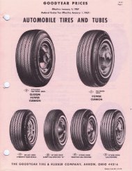
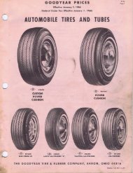
A great deal of ordinary road dirt wimich collects<br />
on white sidewall tires tnay be sponged off with<br />
clear water or e mild soap ealtttiao - Under no cir<br />
cumatera,lces should gasoline, kerosene, nr any<br />
cleeni:Ig fluid 000Lafning a solvent de’rived from<br />
tti[ he used to clean white sidewill tire’s. Mineral<br />
oil in atty form i.c detri mental to ruhher, and a<br />
cleaner cdi r]tan uit base alit dieculur or injure<br />
white sidc’.seti ttrea<br />
IS<br />
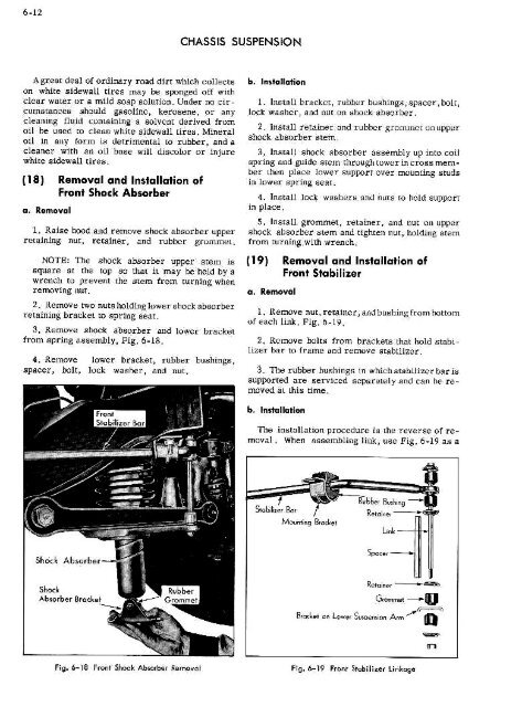
a. Removal<br />
Removal and Installation of<br />
Front Shock Absorber<br />
1 Raiae hood attd remnt,ve shock ahsarher upper<br />
retaining nut, retainer, and m-uhber ga-ummeL,<br />
NOTE; <strong>The</strong> shock aheorher upper stem ta<br />
square at the top Sn tLtat it may he held by a<br />
renal, tu prevent the stem from tu r Iii Etg short<br />
removing co,.<br />
2. Itotnove two nuts baldIng lower shock absarber<br />
retaining ‘ore ek et to spring eea t -<br />
3. Remove shock ahaorher and lower bracket<br />
from spring assembly, Fig - 6-LB -<br />
4 Remnve lower bracket, rtthher hashfngs,<br />
spacer, helt, tuek washer, and not.<br />
b. Instollation<br />
1, Install brecket, rubber hushing.c - .snacer - bolt,<br />
tecTe ssst-.c:r, and nut on shock ahsorbe I -<br />
2 TI alt retainer and r u bhc, r gl-ottttmte L 0mm ttpPo<br />
chock alteurher s,cm -<br />
3. Install shock absorher iisothtv up into can<br />
epring and jide atc-,tt tlmrovglt tower in cross niemher<br />
Lhen place lower support aver nrL:niiag studs<br />
in tower spring seat,<br />
4. InstalL tack wasiters and nuts to hold slmpport<br />
in place.<br />
5. InsTalL gronwnet, retainer, end tmut Ott unpor<br />
shock absorber stem and tighten TtOt, holding item<br />
from turd tog with wrench -<br />
19 Removal and Installation of<br />
Front Stabilizer<br />
a. Removal<br />
I, Remove not, terai:,c-r, attdhuslmingfrom bottom<br />
of each link. Fig. h-19<br />
2 Retnose hubs from arackeic that hnld stahi -<br />
litter bar to franta and rennove stahl] izor.<br />
3. ‘lime rubher hcshin;a in which atabilizer her is<br />
supported are serviced ieparatel y and ran he re<br />
maved eL this Lime<br />
b, ln,tallalian<br />
<strong>The</strong> Installation procedure ii L:le reverse of re<br />
mt,vel . When assembling tink, use Fig. 6-19 a.s a<br />
blerr Ba,<br />
Meae.,9 1,atke!<br />
B,<br />
L,,L --<br />
Spars,<br />
F,ntL’ a,,<br />
Retu,aa, -<br />
Ct..asre<br />
Sea,aaioa Aura<br />
ft -<br />
N . 6-IS Prant Shook Abwtbe r rnosa I Ftg. o_19 Front Stabtlier Unkagn<br />
n