06 - Chassis Suspension - The Old Car Manual Project
06 - Chassis Suspension - The Old Car Manual Project
06 - Chassis Suspension - The Old Car Manual Project

You also want an ePaper? Increase the reach of your titles
YUMPU automatically turns print PDFs into web optimized ePapers that Google loves.
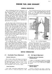
6-I.<br />
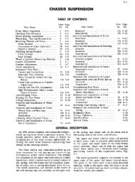
CHASSIS SUSPENSION<br />
<strong>The</strong> chassis suspension system used on 1955<br />
Cadillac cars is very similar to that used on 1954<br />
series cars, and information relative to service<br />
procedures remains the same as that outlined in<br />
Section 6 of the 1954 Shop <strong>Manual</strong>.<br />
Shock absorber valving has beenchanged slightly<br />
to improve ride characteristics and the rear<br />
spring seat has been changed to accommodate the<br />
shock absorber bayonet type lower mounting stud.<br />
Tubeless tires are used as standard equipmcnt<br />
on all 1955 series cars. <strong>The</strong>se tires employ a<br />
butyl liner not puncture sealing, which is an in<br />
tegral part of the tire casing, to protect against<br />
GENERAL DESCRIPTION<br />
SERVICE<br />
1 Checking and Repairing Air Leaks<br />
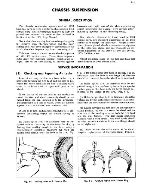
Loss of air may be due to a hole in the tire, a<br />
poor seal between the tire bead and the rim or be<br />
tween the valve stem and the rim, a leaking valve<br />
core, or a loose rivet or open weld joint in the<br />
wheel.<br />
If the source of the air leak is not readily lo<br />
cated, the tire and wheel assembly should be re<br />
moved from the car, inflated to 50 lbs. pressure,<br />
and immersed in a tank of water. When air bubbles<br />
appear, mark location of leak on tire or rim.<br />
If leak is in tire, reduce tire pressure to 10 lbs.<br />
remove puncturing object and repair casing as<br />
follows:<br />
a Holes up to 3/32" in diameter may be re<br />
paired without removing the tire from the rim, by<br />
forcing tire sealing dough in the hole, using a<br />
commercially available pressure gun with the<br />
nozzle held firmly over the hole in the tire. Fig.<br />
hlowouts and rapid loss of air when a puncturing<br />
object penetrates the casing. Tire service infor<br />
mation is covered in the following notes.<br />
Disc wheels, identical to those used on 1954<br />
series cars, are standard equipment on all 1955<br />
series cars except the Eldorado. Forged alumi<br />
num, chrome plated wheels are standard equipment<br />
in the Eldorado styles and are available as op<br />
tional equipment on all other 62 and 605 series,<br />
1955 Cadillac cars.<br />
Wheel mounting studs on the left side have left<br />
hand threads on 1955 series cars.<br />
INFORMATION<br />
6-1. If the nozzle goes into hole in casing, it is an<br />
indication that the hole is too large and the tire<br />
should be removed from the wheel to be repaired.<br />
b Holes up to 1/4’ in diameter may be re<br />
paired using a hot patch or by installing a special<br />
rubber plug in the hole with its large flange ce<br />
mented to the inside of the tire. Fig. 6-2.<br />
c Holes larger than 1/4" in diameter shouldbe<br />
vulcanized by the authorized tire dealer in accord<br />
ance with the instructions of the tire manufacturer.<br />
d Leaks between the rim and the casingneces<br />
sitate removal of the tire from the wheel and in<br />
spection of the sealing area on both the tire bead<br />
and the rim flange. <strong>The</strong> rim flange should be<br />
cleaned with a wire brush. Any weld beads should<br />
be filed smooth and dents in the rim flange should<br />
be straightened.<br />
e Leaks around the valve stem, at the wheel,<br />
require replacement of the valve stem. Fig. 6-3.<br />
Fig. 6-1 Sealing Holes with Pressure Gun Fig. 6-2 Puncture Repair with Rubber Plug
CHASSIS SUSPENSION<br />
Fig. 6-3 Valve Stem Assembly<br />
Before installing a new stem, remove any foreign<br />
material around hole or any burrs which would<br />
prevent seating of the valve stem.<br />
f Occasionally an air leak may be encountered<br />
in the wheel weld joint or at a rivet. If the rivet<br />
is not visibly loose, it may be sealed with a ce<br />
ment, available from tire manufacturers, for this<br />
purpose.<br />
CAUTION: Under no condition should the<br />
rivet or wheel be peened, welded or brazed. Re<br />
place the wheel if the air leak cannot be repaired<br />
with cement or if rivet is noticeably loose. On<br />
the Sabre Spoke aluminum wheels, a sealingtape<br />
is cemented into the tire well to seal the joint<br />
between the aluminum forging and the steel back<br />
rim. Use care not to disturb this tape when<br />
mounting or removing tire.<br />
2 Removal and Installation of Tire<br />
a. Removal<br />
1. Remove valve cap and core.<br />
2. Using a bead breaker tool, force beads away<br />
from rim flange.<br />
CAUTION: <strong>The</strong> use of tire irons for breaking<br />
beads away from rim is not recommended as<br />
there is a possibility of damaging the sealing<br />
surface on the tire bead.<br />
3. Work outside tire bead over rim, starting<br />
adjacent to the valve stem, and then remove the<br />
inside bead.<br />
Fig. 6-4 Expanding Beads Against Rim with<br />
Mounting Band<br />
b. Installation<br />
1. Inspect rim ledges and flanges for foreign<br />
particles and remove with emery cloth or a file.<br />
Straighten rim flange if bent.<br />
2. <strong>Car</strong>efully install beads over rim, usingeither<br />
a special tire installing tool or tire irons. A small<br />
amount of water may be used on the beads to fa<br />
cilitate installation. Soap solutions or solvents<br />
are not recommended. Start tire over rim flange<br />
at a point opposite valve stem so that stem will not<br />
prevent bead from dropping into rim well, as last<br />
section of bead is forced over rim.<br />
3. Install valve core. Place a tire mounting<br />
band around center of tread and engage it to force<br />
tire beads out against rim. Fig. 6-4.<br />
NOTE: If a tire mounting band is not avail<br />
able, a heavy sash cord may be installed around<br />
the tire circumference and tightened with a tire<br />
iron to serve the same purpose.<br />
4. Inflate tire to hold bead against rim approx.<br />
S lbs.. Remove band and Inflate to 50 lbs. pres<br />
sure.<br />
5. Leak test tire and wheel assembly and, if<br />
satisfactory, reduce to recommended pressure.
,<br />
6-3<br />
CHASSIS SUSPENSION<br />
SPECIFICATIONS<br />
Subject and Remarks 55-62, 60S 55-75 55-86 Comm.<br />
King Pin inclination 5° 51’ 5° 51’ 5° 51’<br />
Camber of front wheels -3/8° to /3/8° -3/8° to /3/8° -3/8° to /3/8°<br />
*Caster angle 00 to -1° 0° to 0° to<br />
Toe in <strong>Car</strong> standing 3/16 to 1/4" 3/16" to 1/4" 3/16" to 1/4"<br />
Turning radius 218", 22’b" 25’ 10" 29’<br />
*Adjustment must be within 1/20 or less on both sides of car.<br />
SHOCK ABSORBERS -- Front<br />
Type<br />
Delco Hydraulic Direct Acting<br />
Bore 1’’ 1’’ 1’’<br />
Model No. Replacement Type 542G 542G 542G<br />
SHOCK ABSORBERS -- Rear<br />
Type<br />
Delco Hydraulic Direct Acting<br />
Bore 1" 1" 1"<br />
Model No. Replacement Type 544X 544X 544X<br />
RIMS<br />
Diameter 15" 15" 15"<br />
Width 6" 6" 6’<br />
Eccentricity 3/64" max. 3/64" max. 3/64" max.<br />
Runout 3/64" max 3/64" max. 3/64" max.<br />
TIRES<br />
Inflation pressure, in pounds - -<br />
Front 24 28 24<br />
Rear 24 28 30<br />
Ply rating 4 6 6<br />
Size Black Walls 8,00 x 15 8.00 x 15 8.90 x 15<br />
Size White Walls 8.20 x 15 8.20 x 15 8.90 x 15<br />
WHEELS<br />
Type Slotted Disc Slotted Disc Slotted Disc<br />
Optional -<br />
Sabre Spoke<br />
Aluminum Wheels<br />
Make Kelsey-Hayes Kelsey-Hayes Kelsey-Hayes<br />
Series<br />
55-6019 Without Air Conditioner<br />
55-6219, 6237, and 6237D Without A.C.<br />
55-6267 and 62675 Without A.C.<br />
55-6019, 6219, 6237 and 6237D With A.C.<br />
55-7523 and 7533 Without A.C.<br />
55-7523 and 7533 With A.C.<br />
55-86<br />
55-86 Heavy Duty<br />
Inside diameter of springs is 4.00 inches.<br />
FRONT SPRING DATA CHART<br />
Part No.<br />
1460196<br />
1460194<br />
1460197<br />
1460197<br />
1460192<br />
1460198<br />
1460199<br />
1460998<br />
Color<br />
Daub<br />
Yellow<br />
Light Blue<br />
Aluminum<br />
Aluminum<br />
Orange<br />
Dark Red<br />
Green<br />
None<br />
Normal<br />
Load<br />
2300<br />
2230<br />
2380<br />
2380<br />
2650<br />
2760<br />
2725<br />
3000<br />
Rate<br />
Per In.<br />
NOTE; On cars equipped with Air Conditioner, Spring 1460197 or 1460198 is used on both sides, with<br />
Shim 1457838 on R.H. side only.<br />
350<br />
350<br />
375<br />
375<br />
400<br />
400<br />
540<br />
540
CHASSIS SUSPENSION<br />
Series<br />
REAR SPRING DATA CHART<br />
Part No.<br />
55-6019, 6219, 6237 and 6237D 1460924<br />
Without Air Conditioner<br />
55-6267 and 62675 1460925<br />
Without Air Conditioner<br />
55-6019, 6219, 6237 and 6237D 1460925<br />
With Air Conditioner<br />
55-60 and 62 - Heavy Duty 1460930<br />
55-7523 and 7533 1460927<br />
Except Exports<br />
55-7523 and 7533 - Export 1460929<br />
55-86 1460928<br />
55-86 - Heavy Duty 1460931<br />
Color<br />
Daub<br />
Light Blue<br />
Pink<br />
Pink<br />
Dark Red<br />
Purple<br />
Yellow<br />
None<br />
White<br />
Normal<br />
Load<br />
1190<br />
1260<br />
1260<br />
1330<br />
1440<br />
1430<br />
1700<br />
1900<br />
Rate<br />
Per In.<br />
All springs are 2.50 inches in width. Color daub to appear on rear eye only.<br />
115<br />
120<br />
120<br />
140<br />
140<br />
170<br />
235<br />
235<br />
No. of<br />
Leaves<br />
5<br />
5<br />
5<br />
6<br />
6<br />
7<br />
9<br />
9<br />
SPRING HEIGHTS<br />
<strong>The</strong> spring heights should be:<br />
Model<br />
Front<br />
Weight*<br />
Rear<br />
Front Spring<br />
Height in Inches<br />
Rear Spring<br />
Height in Inches<br />
6019 2455 2250<br />
6237 2390 2170<br />
6237D 2410 2215<br />
6267 2510 2335<br />
6219 2390 2180<br />
7523-33 2700 2500<br />
86 Comm. approx. 2550 3040<br />
4-1/2 to 5-1/4<br />
4-1/2 to 5-1/4<br />
4-1/2 to 5-1/4<br />
4-1/2 to 5-1/4<br />
4-1/2 to 5-1/4<br />
5-3/8 to 6-1/8<br />
5-1/2 to 6-1/4<br />
8-3/4 to 9-1/2<br />
8-3/4 to 9-1/2<br />
8-3/4 to 9-1/2<br />
8-3/4 to 9-1/2<br />
8-3/4 to 9-1/2<br />
10 to 10-3/4<br />
9-5/8 to 10-3/8<br />
‘<strong>Car</strong> weight with full tank of gasoline, heater, radio, and wheel discs.<br />
TORQUE TIGHTNESS<br />
Size<br />
Ft. Lbs.<br />
Mm.<br />
Ft. Lbs.<br />
Max.<br />
Knuckle to brake plate and steering arm 7/16-20<br />
Knuckle support arm - fixed threaded bushings - -<br />
In lower end of knuckle support<br />
Special<br />
In lower suspension arm<br />
Special<br />
In upper suspension arm<br />
Special<br />
Knuckle support, upper and lower, nut<br />
Special<br />
Rubber bumper to lower suspension arm 3/8-24<br />
Spring bolt front end<br />
Special<br />
Spring shackle bushings and hanger bushings<br />
Special<br />
Stabilizer bracket to frame 3/8-24<br />
Steering idler arm threaded bushing<br />
Special<br />
Steering tie rod adjuster clamp bolts 5/16-24<br />
Steering tie rod pivots to steering arms 1/2-20<br />
<strong>Suspension</strong> arm shaft to frame lower 7/16-20<br />
<strong>Suspension</strong> arm shaft to frame upper 9/16-18<br />
Wheel mounting nuts 1/2-20<br />
Wheel mounting nuts Lefthand threads on left side<br />
60<br />
200 Mm.<br />
195<br />
140<br />
70<br />
16<br />
65<br />
65<br />
25<br />
110<br />
20<br />
50<br />
60<br />
150<br />
90<br />
70<br />
205<br />
150<br />
90<br />
20<br />
75<br />
75<br />
30<br />
115<br />
20<br />
55<br />
70<br />
160<br />
100