HYDRA-MATIC TRANSMISSION - The Old Car Manual Project
HYDRA-MATIC TRANSMISSION - The Old Car Manual Project
HYDRA-MATIC TRANSMISSION - The Old Car Manual Project

Create successful ePaper yourself
Turn your PDF publications into a flip-book with our unique Google optimized e-Paper software.
14-4<br />
<strong>HYDRA</strong>-<strong>MATIC</strong> <strong>TRANSMISSION</strong><br />
SERVICE<br />
INFORMATION<br />
With the exception of a few changes, the Service<br />
Information contained in the 1954 Shop <strong>Manual</strong> will<br />
be applicable to all 1955 Hydra-Matic Transmis<br />
sions. Make certain the following information is<br />
thoroughly reviewed before proceeding with any<br />
service work.<br />
1 Minor Changes<br />
a. Correction of Leaks at Fluid Coupling<br />
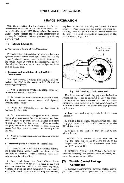
requires expanding the ring until free of piston<br />
groove. When installing the piston and ring as<br />
sembly, Tool No. J-5608 may be used to compress<br />
the seal ring until assembly is positioned in the<br />
clutch cover. Fig. 14-4.<br />
Ring compressor<br />
Tool i-5608<br />
Procedure for determining at which point leak<br />
age occurs will differ from 1954 because of the one<br />
piece flywheel housing used in 1955. Removal of<br />
the cover plate in front of the housing will permit<br />
checking for leaks at torus cover to flywheel bolts<br />
and at drain plug.<br />
b. Removal and Installation of Hydra-Matic<br />
Transmission<br />
<strong>The</strong> 1-lydra-Matic removal and installation pro<br />
cedure for 1955 is the same as in 1954 with the<br />
following exceptions:<br />
1. With a one piece flywheel housing, there will<br />
be no lower cover to remove.<br />
2. To reach the torus cover to flywheel mount<br />
ing bolts, remove starter motor and flywheel<br />
housing front cover.<br />
3. Drain the transmission, as described in<br />
Section 2, Note lOb.<br />
4. On transmissions equipped with oil cooler,<br />
hoses at cooler must first be removed and hose<br />
ends plugged to prevent coolant leakage and entry<br />
of dirt or other foreign matter. When removing<br />
oil pan, exercise caution when disconnecting the<br />
pump feed line from the cooler valve body in the<br />
oil pan.<br />
5. When installing transmission, observe changes<br />
noted above.<br />
c. Disassembly and Assembly of Transmission<br />
1. Planet <strong>Car</strong>rier - With smaller planet pinions,<br />
the bronze thrust washer inside the planet carrier<br />
can now be removed. Upon assembly, make cer<br />
tain washer is reinstalled.<br />
2. Front and Rear Unit Outer Clutch Piston<br />
Seals - <strong>The</strong> outer clutch piston seals in the front<br />
and rear units for 1955 are cast iron ring seals,<br />
whereas in 1954 the seals consisted of anexpander<br />
and rubber seal. Removal of the ring seal merely<br />
Fig. 14-4 Installing Clutch Piston Seal<br />
<strong>The</strong> front unit oil seal ring gap must be held to<br />
specification. This is required to allow for more<br />
tolerance of the front clutch drum bore. All mea<br />
surements must be taken with ring located squarely<br />
in clutch drum bore. To check ring gap, proceed<br />
as follows;<br />
a. Insert oil seal ring squarely in clutch drum<br />
assembly.<br />
b. Using a feeler gage, check the ring gap. <strong>The</strong><br />
ring gap limits are .OOl"-.OOô" measured at the<br />
OD of the ring.<br />
c. If gap is too tight, it may be filed to fall<br />
within limits.<br />
NOTE: <strong>Car</strong>e should be exercised not to<br />
file the ring gap so as to allow the OD to be<br />
longer than the ID. <strong>The</strong> maximum taper must<br />
be .007" gap at ID.<br />
3. CONTROL VALVE ASSEMBLY - Service op<br />
erations covering the control valve assembly re<br />
main the same as for 1954.<br />
2 Throttle Control Linkage<br />
Adjustment<br />
1. Remove transmission throttle control clevis<br />
pin, and check lever position with Tool No.