HYDRA-MATIC TRANSMISSION - The Old Car Manual Project
HYDRA-MATIC TRANSMISSION - The Old Car Manual Project
HYDRA-MATIC TRANSMISSION - The Old Car Manual Project

You also want an ePaper? Increase the reach of your titles
YUMPU automatically turns print PDFs into web optimized ePapers that Google loves.
14-2<br />
F-IYDRA-<strong>MATIC</strong><br />
<strong>TRANSMISSION</strong><br />
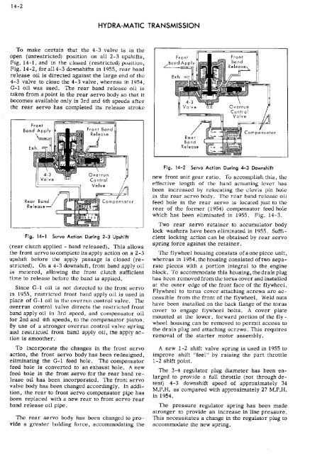
To make certain that the 4-3 valve is in the<br />
open unrestricted position on all 2-3 upshifts,<br />
Fig. 14-1, and in the closed restricted position,<br />
Fig. 14-2, for a114-3 downshifts in 1955, rear hand<br />
release oil is directed against the large end of the<br />
4-3 valve to close the 4-3 valve, whereas in 1954,<br />
G-1 oil was used. <strong>The</strong> rear band release oil is<br />
taken from a point in the rear servo body so that it<br />
becomes available only in 3rd and 4th speeds after<br />
the rear servo has completed its release stroke<br />
Fig. M-2 Servo Action During 4-3 Downshift<br />
Fig. 14-1 Servo Action During 2-3 Upshift<br />
rear clutch applied - hand released. This allows<br />
the front servo to complete its apply action on a 2-3<br />
upshift before the apply passage is closed re<br />
stricted. On a 4-3 downshift, front band apply oil<br />
is metered, allowing the front clutch sufficient<br />
time to release before the band is applied.<br />
Since C-i oil is not directed to the front servo<br />
in 1955, restricted front band apply oil is used in<br />
place of C-I oil in the overrun control valve. <strong>The</strong><br />
overrun control valve directs the restricted front<br />
band apply oil in 3rd speed, and compensator oil<br />
for 2nd and 4th speeds, to the compensator piston.<br />
By use of a stronger overrun control valve spring<br />
and restricted front band apply oil, the apply ac<br />
tion is smoother,<br />
To incorporate the changes in the front servo<br />
action, the front servo body has been redesigned,<br />
eliminating the C-I feed hole. <strong>The</strong> compensator<br />
feed hole is converted to an exhaust hole. A new<br />
feed hole in the front servo for the rear band re<br />
lease oil has been incorporated. <strong>The</strong> front servo<br />
valve body has been changed accordingly. In addi<br />
tion, the rear to front servo compensator pipe has<br />
been replaced with a new rear to front servo rear<br />
band release oil pipe.<br />
<strong>The</strong> rear servo body has been changed to pro<br />
vide a greater holding force, accommodating the<br />
new front unit gear ratio. To accomplish this, the<br />
effective length of the band actuating lever has<br />
been increased by relocating the clevis pin hole<br />
in the rear servo body. <strong>The</strong> rear band release oil<br />
feed hole in the rear servo is located just to the<br />
rear of the former 1954 compensator feed hole<br />
which has been eliminated in 1955. Fig. 14-3.<br />
Two rear servo retainer to accumulator body<br />
lock washers have been eliminated in 1955. Suffi<br />
cient locking action can be obtained by rear servo<br />
spring force against the retainer.<br />
<strong>The</strong> flywheel housing consists ofaone piece unit,<br />
whereas in 1954,thehousing consisted of two sepa<br />
rate pieces with a portion integral to the engine<br />
block. To accommodate this housing, the drain plug<br />
has been removed from the torus cover and installed<br />
at the outer edge of the front face of the flywheel.<br />
Flywheel to torus cover attaching screws are ac<br />
cessible from the front of the flywheel. Weld nuts<br />
have been installed on the back flange of the torus<br />
cover to engage flywheel bolts. A cover plate<br />
mounted at the lower, forward portion of the fly -<br />
wheel housing can be removed to permit access to<br />
the drain plug and attaching screws. This requires<br />
removal of the starter motor assetnbly.<br />
A new 1-2 shift valve spring is used in 1955 to<br />
improve shift "feel" by raising the part throttle<br />
1-2 shift point.<br />
<strong>The</strong> 3-4 regulator plug diameter has been en<br />
larged to provide a full throttle not through de<br />
tent 4-3 downshift speed of approximately 34<br />
M.P.H. as compared with approximately 27 M.P.FI.<br />
in 1954.<br />
<strong>The</strong> pressure regulator spring has been made<br />
stronger to provide an increase in line pressure.<br />
This necessitates a change in the regulator plug to<br />
accommodate the new spring.