model if114 vats/passlock/transponder universal ... - Bulldog Security
model if114 vats/passlock/transponder universal ... - Bulldog Security
model if114 vats/passlock/transponder universal ... - Bulldog Security

Create successful ePaper yourself
Turn your PDF publications into a flip-book with our unique Google optimized e-Paper software.
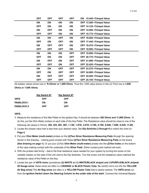
1/31/02<br />
OFF OFF OFF OFF ON 12.445 +Trimpot Value<br />
ON ON ON ON OFF 13.300 +Trimpot Value<br />
OFF ON ON ON OFF 14.125 +Trimpot Value<br />
ON OFF ON ON OFF 14.950 +Trimpot Value<br />
OFF OFF ON ON OFF 15.775 +Trimpot Value<br />
ON ON OFF ON OFF 16.620 +Trimpot Value<br />
OFF ON OFF ON OFF 17.445 +Trimpot Value<br />
ON OFF OFF ON OFF 18.270 +Trimpot Value<br />
OFF OFF OFF ON OFF 19.095 +Trimpot Value<br />
ON ON ON OFF OFF 19.950 +Trimpot Value<br />
OFF ON ON OFF OFF 20.775 +Trimpot Value<br />
ON OFF ON OFF OFF 21.600 +Trimpot Value<br />
OFF OFF ON OFF OFF 22.425 +Trimpot Value<br />
ON ON OFF OFF OFF 23.270 +Trimpot Value<br />
OFF ON OFF OFF OFF 24.095 +Trimpot Value<br />
ON OFF OFF OFF OFF 24.920 +Trimpot Value<br />
OFF OFF OFF OFF OFF 25.745 +Trimpot Value<br />
All resistor values shown are in ‘K-Ohms’ or 1,000 Ohms. Thus the 1.650 value shown in the (3) Third row is 1,650<br />
Ohms or 1.65K Ohms.<br />
Dip Switch #1 Dip Switch #7<br />
VATS OFF OFF<br />
PASSLOCK I ON ON<br />
PASSLOCK II OFF OFF<br />
VATS:<br />
1. Measure the resistance of the little Pellet on the Ignition Key. It should be between 392 Ohms and 11,800 Ohms. To<br />
do this, put the Ohm Meter probes on each side of the Key Pellet. The Resistance value should be close to one of the<br />
following (all values in Ohms): 392, 523, 681, 887, 1.13K, 1.87K, 3.01K, 3.74K, 4.75K, 6.04K, 7.50K, 9.53K, 11.8K.<br />
2. Locate the closest value that is less than your desired value. Set Dip Switches 2 through 6 to match the chart on<br />
Page 4.<br />
3. Put your Ohm Meter (multi-meter) probes on the (2)Two Silver Resistance Measuring Pads through the opening<br />
shown in the drawing – making good contact with these (2)Two Silver Resistance Measuring Pads on the board.<br />
(See drawing on page 1). Or put your (2)Two Ohm Meter (multi-meter) probes into the (2)Two holes on the bottom<br />
of the case making contact with the underside of the Silver Pads. Either contact point method will work.<br />
4. With the probes held firmly – dial-in the final resistance value needed for your system by turning the screw on the<br />
variable resistor on the side of the unit next to the Dip Switches. Turn the screw unit the resistance value matches the<br />
resistance value of the Pellet on the Key.<br />
5. Locate the pair of VATS wires (sometimes (2) WHITE or (1) WHITE/BLACK striped and (1)PURPLE/BLACK striped)<br />
20 Gauge wires, these wires are often in a ORANGE or BLACK Plastic Tube. Be careful not to cut into the YELLOW<br />
Air Bag wires! The Air Bag wires are often in a YELLOW Plastic Tube that is clearly marked. The VATS wires run<br />
from the Ignition Switch down the Steering Column to the under side of the dash. Connect the Universal Bypass<br />
4