INSTALLATION GUIDE ⢠OWNER'S GUIDE - Bulldog Security
INSTALLATION GUIDE ⢠OWNER'S GUIDE - Bulldog Security
INSTALLATION GUIDE ⢠OWNER'S GUIDE - Bulldog Security

You also want an ePaper? Increase the reach of your titles
YUMPU automatically turns print PDFs into web optimized ePapers that Google loves.
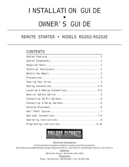
<strong>INSTALLATION</strong> <strong>GUIDE</strong><br />
•<br />
OWNER’S <strong>GUIDE</strong><br />
REMOTE STARTER • MODELS RS202/RS202E<br />
CONTENTS<br />
System Features ......................................1<br />
System Components ....................................1<br />
Required Tools .......................................1<br />
Technical Assistance .................................1<br />
Before You Begin .....................................2<br />
Precautions ..........................................2<br />
Testing Your Wires ...................................2<br />
Making Connections .................................2-4<br />
Locating & Making Connections ......................4-5<br />
Neutral Safety Switch ................................5<br />
Connecting 18-Pin Harness ............................6<br />
Connecting 4-Relay Harness ...........................6<br />
Antenna Placement ....................................6<br />
Anti-Theft System ....................................7<br />
Optional Connections ...............................7-9<br />
Operating Instructions ...............................9<br />
Programming Instructions ..........................9-10<br />
Technical Assistance<br />
All tech personnel are expertly qualified to answer any technical questions.<br />
Technicians are available Monday through Friday from 9:00 a.m. until 8:00 p.m. and Saturday 10:00 a.m. until 4:00 p.m.<br />
Address<br />
288 Canton Avenue • Wintersville, Ohio 43953<br />
Telephone<br />
Phone: 740-264-4710 • 800-878-8007 • Fax: 740-264-7306
SYSTEM FEATURES<br />
Four-Button Extended Range<br />
Remote Control<br />
Keyless Entry<br />
Trunk Release<br />
Remote Programmable Run Time<br />
Run Time Confirmation<br />
Tach/Tachless Option<br />
Parking Light Confirmation<br />
Dome Light Supervision<br />
Cold Start<br />
Automatic Start<br />
Pit Stop Mode<br />
Extended Range Antenna<br />
Code Learning<br />
Remotely start your car to run the heater or air conditioning from an extended distance.<br />
Remotely locks and unlocks your power door locks.<br />
Remotely opens your trunk with a push of a button. (Optional part #775 required)<br />
Remotely program your vehicle to run 5 to 15 minutes.<br />
Lets you check the run time that the unit is programmed for.<br />
A programmable feature that lets you choose from the easy to install tachless operation or<br />
the standard wire-in, tach operation.<br />
Confirms that your vehicle has received a remote signal and will remain on if the engine is<br />
remotely started.<br />
Never walk up to a dark vehicle again. When unlocking the vehicles doors by remote control<br />
the dome light will come on and stay on for 1 minute, or until you activates the ignition<br />
switch. (Optional part #775 required)<br />
Remotely program your car to start at a preset temperature. Automatically starts your car in<br />
freezing temperature so you never have a dead battery.<br />
Remotely program your car to start every 3 hours regardless of temperature.<br />
Allows you to exit the vehicle while the engine remains running.<br />
Allows you to operate your system from up to 400 feet away. (800 feet for E Models)<br />
Allows your remote starter to learn new remotes, should you want to add remotes, or if remotes<br />
are lost.<br />
SYSTEM COMPONENTS<br />
Your system includes:<br />
1-Installation & Operation Guide<br />
1-Main Control Module<br />
2-Four Button Remote Transmitter with Slide Protectors<br />
1-(4) Relay Harness with Relays<br />
1-18-Pin Wire Harness<br />
1-Hood Pin Switch<br />
1-Extended Range Antenna (E Model Only)<br />
2-Window Clips (E Model Only)<br />
1-Warranty<br />
1-Warning Sticker for Under the Hood<br />
2-<strong>Bulldog</strong> Window Decals<br />
REQUIRED TOOLS<br />
You will need a computer-friendly test light and a 5/16 drill bit when mounting the hood pin switch. In<br />
most cases no additional tools are required, however if the bottom of your dash on the driver’s side will<br />
come off you must remove it. In this case a screwdriver or socket set may be needed.<br />
TECHNICAL ASSISTANCE<br />
Should you need help. First check our website at www.bulldogsecurity.com/wires.htm or call our toll-free<br />
Tech Support Hotline Monday through Friday 9AM-8PM and Saturday 10AM-4PM EST at 800-878-8007.<br />
You must give the following information:<br />
•Name<br />
•Telephone Number with Area Code (Fax number if applicable)<br />
•Year, Make, and Model of the vehicle<br />
•The model number of the system you are installing<br />
•The type of assistance you are requesting<br />
If you give the above information you will be called back as soon as possible, usually within 10 minutes.<br />
1
BEFORE YOU BEGIN<br />
Congratulations, you have purchased one of the most advanced remote starter systems ever made. Your new<br />
remote starter is a technological breakthrough utilizing the most advanced, state of the art technology<br />
and components. It is computer controlled and manufactured in the U.S.A. The dependability and variety of<br />
features make <strong>Bulldog</strong> <strong>Security</strong> the leader in the industry. Enjoy your new remote starter for years to<br />
come!<br />
This remote system is designed to start your vehicle by sending a command signal from the remote transmitter<br />
or by programming automatic temperature or timed start. It is required that your installation is done in<br />
a well-ventilated area. It is the responsibility of the owner to ensure that the remote system is not<br />
used to start the vehicle in an undesired location.<br />
It is recommended that a carbon monoxide detector be installed in the living area near a location where<br />
the vehicle may be garaged.<br />
Since there are many different makes and models of vehicles, look at the wiring chart on or our website,<br />
www.bulldogsecurity.com/wires.htm.<br />
Read this manual thoroughly before starting the installation. You must also decide if any options are<br />
desired such as trunk release and dome light supervision. An optional relay will be needed for these<br />
options. Please do not skip any steps.<br />
TACH/TACHLESS OPERATION<br />
In most cases the decision to go with tachless mode will save time during the installation. If your vehicle<br />
is hard-starting then you should use tach mode.<br />
MAKE SURE YOU PLACE THE WARNING STICKER UNDER THE HOOD.<br />
PRECAUTIONS<br />
This system is designed to be used with fuel-injected,<br />
automatic transmission vehicles only.<br />
SAFETY FIRST!<br />
Never start your vehicle if it is indoors, if the keys are in the ignition and you’re sure the car is in<br />
park. A periodic safety check is recommended to ensure that your system is in proper working order.<br />
DO NOT use mechanical wiring connections, such as crimp or snap together taps. Follow instructions<br />
below.<br />
DO NOT disconnect the battery if the vehicle has an anti-theft-coded radio or is equipped with an airbag.<br />
Doing so may cause a warning light to be displayed and may require a trip to the dealer to be corrected.<br />
DO NOT leave the interior or exterior lights on for an extended period of time as it may cause battery<br />
drain. Remove the dome light fuse from the fuse box. NOTE: Starter systems do not work well with a partially<br />
discharged battery.<br />
DO NOT mount the control module until all connections have been made and tested. Using wire ties or<br />
double sided tape, MOUNT THE MODULE UNDER THE DASH. Place the warning sticker under the hood.<br />
WARNING!<br />
GENERAL MOTORS REAR WHEEL DRIVE VEHICLES AND DODGE DAKOTAS<br />
All General Motors rear wheel drive vehicles and Dodge Dakotas built prior to 1996 do not have an<br />
electrical Neutral Safety switch. They have a mechanical neutral safety switch. The mechanical neutral<br />
safety switch operates as follows.<br />
a)The key will only turn to start position when the gear selector is in park or neutral.<br />
b)The key can only be removed from the ignition switch when the gear selector is in the park<br />
position.<br />
You must use special precautions with this system.<br />
TESTING YOUR WIRES<br />
When testing for a positive or negative voltage, you must use a computer friendly test light (logic probe)<br />
or a volt/ohm meter. Make sure to probe and test each wire before making your connections.<br />
2
MAKING WIRING CONNECTIONS<br />
1. Strip back two inches of insulation on the wire from the keyless entry.<br />
Two Inches of Bare Wire<br />
2. Strip back one inch of insulation on the wire you need to connect to.<br />
One Inch of Bare Wire<br />
3. Separate the vehicle wire as shown. Make the separation large enough to fit the other wire<br />
through.<br />
4. Insert the wire from the unit through the hole as shown.<br />
5. Wrap the wire around one side then the other and finally around itself as shown.<br />
2<br />
1<br />
3<br />
6. Use electrical tape to wrap. Be sure to cover the wire about two inches on either side of the<br />
connection. First pull the wire that you have just connected along side the wire you connected<br />
to, tape and wire tie them together. Use this method for all connections.<br />
Wire Tie<br />
Electrical Tape<br />
CAUTION: All wires must be wrapped and taped.<br />
MAKING END TO END CONNECTIONS<br />
FOLLOW THESE INSTRUCTIONS<br />
1. When tying two separate wires together at their ends, strip back 1” of insulation on both<br />
wires and separate the strands of wire as shown below.<br />
3
2. Twist upper wires together, twist lower wires together as shown.<br />
3. Lay upper twisted pair of wires over right wire as shown. Bring lower twisted pair of wires<br />
up to meet the left wire as shown.<br />
4. Use electrical tape to wrap, be sure to cover about 2 inches on either side of connection.<br />
Secure with wire ties as shown.<br />
Electrical Tape<br />
Wire Tie<br />
Wire Tie<br />
Use this method ONLY when connecting two separate wires end to end.<br />
LOCATING & MAKING CONNECTIONS<br />
Please see the wiring chart on our website, www.bulldogsecurity.com.<br />
CONSTANT POWER (+12V, key in any position including off)<br />
These wire(s) are in your vehicle’s main ignition harness, usually located on the steering column coming<br />
from the ignition switch. Probe each wire with your test light. The correct wire(s) will show +12V when<br />
the ignition switch is in these 5 positions (ACC-LOCK-OFF-RUN-CRANK).<br />
1. If your vehicle has only (1) constant power wire, attach the<br />
IGNITION HARNESS<br />
RED wire from the 18-pin harness and both large RED wires from<br />
UNDER DASH<br />
the 4-relay harness to the constant power wire in the vehicle.<br />
2. If your vehicle has (2) constant power wires, attach the RED<br />
wire from the 18-pin harness and (1) large RED wire from the<br />
4-relay harness to one of these constant power wires. Then<br />
connect the other large RED wire from the 4-relay harness to the<br />
second constant power wire in the vehicle.<br />
Make sure to wrap electrical tape around all (3) fuse holders to prevent shorting to ground.<br />
IGNITION WIRE(S) (+12V in run and crank position only)<br />
The ignition wire(s) are also located in the main harness coming from the ignition switch. Probe each<br />
wire with your test light, the correct wire(s) will show +12V only when the ignition switch is in the<br />
RUN AND CRANK positions only. The correct wires will not show +12V when in the OFF or ACCESSORY position.<br />
Most Ford, GM, and Chrysler vehicles have at least (2) ignition wires. Most foreign vehicles have only<br />
(1).<br />
1. Strip back the YELLOW wire from the 18-pin harness and then strip back (1) of the (2) WHITE wires<br />
from the 4-relay harness and twist both of these wires together.<br />
4
2. Connect the YELLOW wire and the WHITE wire from step (1) to the ignition wire in the main harness.<br />
If your vehicle has only (1) ignition wire, tape off the end of the second WHITE wire from the 4-<br />
relay harness and do not use.<br />
3. If your vehicle has (2) ignition wires, connect the second WHITE wire from the 4-relay harness to<br />
it.<br />
4. If your vehicle has (3) ignition wires (some GMs) connect the second WHITE wire from the 4-relay<br />
harness to both the second and third ignition wires in the vehicle.<br />
ACCESSORY WIRE(S) THAT POWER THE HEATER/BLOWER MOTOR<br />
(+12V in run or on positions) This wire is also in the main ignition switch harness usually located in<br />
the steering column. Make all connections as close to the ignition switch harness as possible.<br />
Most vehicles will have (1) accessory wire; however some Fords, newer GM vehicles and Chrysler 94 and<br />
up will have (2) or more accessory wires. To locate these wire(s) probe for wire(s) that only show +12V<br />
when the ignition switch is in the RUN or ON positions. This wire(s) will not show +12V when the ignition<br />
switch is in any other position.<br />
1.If your vehicle has only (1) accessory wire connect the WHITE WITH BLACK STRIPE wire from the 4-relay<br />
harness to this wire.<br />
2.If your vehicle has (2) accessory wires, connect the WHITE WITH BLACK STRIPE wire to both.<br />
3.If your vehicle has (3) accessory wires connect the unused WHITE wire from the 4-relay harness to the<br />
third accessory wire.<br />
STARTER/CRANK WIRE (+12V only in the start position only)<br />
The starter/crank wire is also in the main harness. Locate the wire that shows +12V only in the crank<br />
position. This wire will not show +12V in any other position. Attach the YELLOW WITH BLACK STRIPE wire<br />
from the 4-relay harness to this wire.<br />
CHASSIS GROUND<br />
Factory Bolt<br />
Locate an easy to get to bolt or screw<br />
located under the driver’s side of the dash and<br />
attach the BLACK ground wire from the 18-pin<br />
harness securely as pictured.<br />
Spade Connector<br />
Black Ground Wire<br />
Note: Remove any paint below<br />
the spade connector.<br />
PARKING LIGHTS (+12V only with parking lights on)<br />
Turn the parking lights to the ON position. (NOT YOUR HEADLAMPS).<br />
Probe the wire(s) coming from your headlamp control switch. Find<br />
a wire that will show +12V only when the parking lights are ON.<br />
Connect the BROWN wire from the 18-pin harness to this wire. If<br />
this wire tests as a (-) negative, see diagram.<br />
WHITE<br />
Brown wire<br />
from 18 pin<br />
harness<br />
YELLOW<br />
87a<br />
To (-)Parking<br />
Light Output<br />
BLACK<br />
To Ground<br />
NEGATIVE PARKING LIGHT OUTPUT<br />
BLUE To Ground<br />
Optional part #775 required. RED<br />
DO NOT USE THE RED WIRE, TAPE OFF.<br />
BRAKE INPUT<br />
The brake wire is located on the switch near and above the brake pedal. The correct wire will show<br />
+12V only when the brake is pressed. Connect the BLUE WITH BLACK STRIPE from the 18-pin harness to this<br />
wire.<br />
FACTORY ALARM SHUT DOWN WIRE (FASD) (-)<br />
If your vehicle is equipped with a factory alarm system (as most vehicles with a factory keyless entry<br />
are) probe for a small gauge wire (usually found in the driver’s side kick panel) that shows (-) ground<br />
when the door lock cylinder is turned to the unlock position using the key. This wire will usually show<br />
a (+) positive voltage before turning the key. NOTE: Some factory disarm wires remain neutral before<br />
you turn the key to unlock instead of +12v positive. Connect the RED WITH BLACK STRIPE wire from the<br />
18-pin harness to this wire.<br />
HOOD PIN SWITCH<br />
This feature will keep the engine from starting or shut off the engine when the hood is opened.<br />
Locate a good chassis ground, if at all possible do not install the pin switch in the rain gutter.<br />
Drill a 5/16 hole, insert the pin switch into the hole and tighten. Check for the hood adjustment,<br />
there is approximately 1/4” adjustment in the pin switch. Close the hood easy, making sure that<br />
the pin switch is not keeping the hood from closing all the way, if it does, cut off approximately<br />
1/8” of the black plastic off of the top of the hoodpin switch and try closing the hood again.<br />
Check to make sure that the hoodpin switch remains neutral when the hood is closed and shows ground<br />
when the hood is open. Plug the BLACK WITH BLUE STRIPE wire from the 18-pin harness into the bottom<br />
of the hood pin switch.<br />
TACH INPUT (Optional)<br />
By this time, you should have determined the way you want your vehicle to start (tach or tachless).<br />
If you have chosen the TACHLESS start option, simply proceed to the next step and skip the following<br />
connection instructions. Make sure to tape the BLACK WITH WHITE STRIPE wire up if not used. For<br />
TACH mode connect the BLACK WITH WHITE STRIPE wire from the 18-pin harness to the negative side<br />
of the coil or the tach wire at the coil pack under the hood. To find the coil pack follow the<br />
5
spark plug wires back to the termination point. To operate in tach mode, make sure to program tach<br />
option, see programming tach option page 10.<br />
NEUTRAL SAFETY SWITCH<br />
MECHANICAL NEUTRAL SAFETY SWITCH (Rear Wheel Drive Only)<br />
When installing a <strong>Bulldog</strong> remote starter on GM vehicles or Dodge Dakotas built prior to 1996, you<br />
must:<br />
Use the diagram below to create a circuit that will prevent the remote starter from starting the<br />
vehicle unless the key is removed from the ignition switch.<br />
Key<br />
Cylinder<br />
Driver’s Door Switch<br />
TAN<br />
GREEN<br />
Ground<br />
Message<br />
center or<br />
key buzzer<br />
PRE-1996 GM REAR WHEEL DRIVES WITH PURPLE CRANK WIRE<br />
Optional part #775 required.<br />
Tie into<br />
heavy white<br />
wire on<br />
4-relay<br />
harness<br />
WHITE<br />
5 Amp<br />
fuse<br />
86<br />
(-) Negative<br />
hood pin wire<br />
BLUE<br />
YELLOW<br />
87<br />
87a<br />
30<br />
Ground<br />
85<br />
BLACK<br />
RED<br />
NOT USED,<br />
TAPE OFF<br />
BLACK/LT.BLUE<br />
Key<br />
Cylinder<br />
LT.BLUE/GREEN<br />
PRE-1996 DODGE DAKOTAS<br />
Optional part #775 required.<br />
Driver’s Door Switch<br />
Message<br />
center or<br />
key buzzer<br />
CONNECTING THE 18-PIN HARNESS & 4-RELAY HARNESS<br />
Ground<br />
Tie into<br />
heavy white<br />
wire on<br />
4-relay<br />
harness<br />
WHITE<br />
5 Amp<br />
fuse<br />
86<br />
(-) Negative<br />
hood pin wire<br />
BLUE<br />
YELLOW<br />
87<br />
87a<br />
30<br />
85<br />
Ground<br />
BLACK<br />
RED<br />
NOT USED,<br />
TAPE OFF<br />
YELLOW<br />
ANTENNA<br />
Keep as<br />
straight as<br />
possible,<br />
tape end<br />
to hold<br />
straight.<br />
WHT/BLK 16 ga.<br />
WHITE 16 ga.<br />
YEL/BLK 16 ga.<br />
For Passlock I<br />
WHT/BLK 16 ga<br />
For Passlock II<br />
WHITE 16 ga<br />
For Passlock I<br />
YEL/BLK 16 ga<br />
Tap here when<br />
installing bypass<br />
module 721.<br />
BROWN/BLACK<br />
GREEN/BLACK<br />
BLACK/WHITE<br />
BLACK/BLUE<br />
BLUE<br />
VIOLET<br />
WHITE/RED<br />
ORANGE<br />
BROWN<br />
GRAY<br />
GRAY/BLACK<br />
YELLOW<br />
BLUE/BLACK<br />
BLACK/YELLOW<br />
GREEN<br />
RED/BLACK<br />
BLACK<br />
RED<br />
RED<br />
RED<br />
WHITE<br />
WHITE<br />
(+) or (-) Door Lock pulse<br />
(-) or (+) Door Unlock pulse<br />
Tach (-) to neg. side of coil<br />
(-) To hood pin switch<br />
(-) Aux. alarm channel input<br />
(-) Dome light supervision<br />
(-) Trunk release<br />
(not used)<br />
(+) Parking lights<br />
(not used)<br />
(not used)<br />
Ignition input<br />
(+) Brake switch<br />
(not used)<br />
(not used)<br />
(-) Factory alarm shutdown<br />
Ground<br />
To +12V constant<br />
750ma (-)<br />
Outputs<br />
YELLOW/BLACK<br />
WHITE/BLACK<br />
2 Red wires need<br />
+12V constant.<br />
Either white wire<br />
to Ignition 1.<br />
If your car has<br />
2 ignitions use<br />
both.<br />
To Starter/Crank<br />
Wire<br />
To Accessory<br />
Wire(s) that run<br />
the Heater/Blower<br />
Motor. Attach at<br />
the ignition<br />
switch wire<br />
harness only.<br />
CAUTION: Before connecting the 18-pin<br />
harness to the module, double check all<br />
connections to be sure they are secure<br />
and properly wrapped with electrical tape.<br />
Mount the unit under the driver’s side<br />
dash. Make sure to properly place antenna.<br />
(See antenna placement page 15.) Plug the<br />
18-pin harness into the main control<br />
module. Once it is plugged in, press and<br />
release transmitter button #4, the parking<br />
lights flash 3 times. The flash confirms<br />
that the transmitter code has been<br />
programmed to the unit. Once the module<br />
is programmed, connect the 3-pin harness<br />
from the 4-relay harness to the module.<br />
NOTE: There are several wires in the 18-<br />
pin harness that will not be used. All<br />
unused wires must be taped.<br />
Press the start button, the parking lights<br />
will flash once and the vehicle will start<br />
and run. If your vehicle starts and remains<br />
running and you wish to connect your door<br />
locks, proceed to page 16, “Testing Door<br />
Locks”, and follow the provided instructions.<br />
NOTE: If your vehicle does not start and<br />
run you may have a factory anti-theft<br />
system. Refer to pages 15 and 21 to see<br />
if this applies to your vehicle.<br />
6
ANTENNA PLACEMENT<br />
ANTENNA<br />
For best results, run the antenna (YELLOW WIRE<br />
WITH BLACK TIP from the back of the unit) as<br />
straight as possible. Do not place the antenna<br />
next to any metal parts or the vehicle’s main<br />
computer control module. Range is up to 400 feet.<br />
Antenna Wire<br />
Antenna Tube<br />
E MODEL REMOTE STARTERS<br />
Run the antenna up the windshield pillar on the<br />
driver’s side and across the top of the windshield<br />
Control Module<br />
to the center, behind the rearview mirror. Use<br />
the antenna clips provided to hold it in place. Be sure to expose the full length of the clear<br />
antenna. It will perform best if mounted vertically, below the dark windshield tint. Never leave<br />
antenna in headliner. Range is up to 800 feet. Each receiver is tested to more than 400 feet<br />
(800 feet, E models) of clear air reception. While many times you will see a higher range. Many<br />
factors will affect the range, including the amount of radio signals in the area, battery strength,<br />
window tint, etc.<br />
FACTORY ANTI-THEFT SYSTEMS<br />
FOR GENERAL MOTORS CARS ONLY<br />
System 1: PASSKEY I and II system (1985 and up). This system has a resistor pill in the key. Measure<br />
resistance of the pill using a test meter. A bypass module is available, part #VATS-WR module.<br />
System 2: PASSLOCK I and II system (1995 and up). Passlock does not have a pill in the key. It has a<br />
light on the dash that states ANTITHEFT OR SECURITY system. A bypass module is available, part #GMBP-<br />
721 module.<br />
System 3: PASSKEY III system (GM 1998 and up). Passkey III is GMs version of a transponder system. This<br />
key will have the letters PK3 on it. A bypass module is available. (Part #781)<br />
FORD ANTI-THEFT SYSTEM: PATS<br />
Ford uses a bypass part #FBP-718 module, 1995-1998. (1999 and up will use part #781.)<br />
CHRYSLER AND MOST IMPORTS ANTI-THEFT SYSTEM: TRANSPONDER<br />
1998 and up will use part #781.<br />
To order these bypass modules call 1-800-878-8007.<br />
OPTIONAL CONNECTIONS<br />
TESTING: Door Locks<br />
There are three basic types:<br />
“Type A” Door Lock Test (Most GMs and some Chryslers)<br />
Probe both of your door lock wires going to the door lock switch usally located in the driver’s kick<br />
panel. Attach the clip end of your test light to a good chassis ground. Using the vehicle’s door lock<br />
controls, activate the lock then the unlock, testing both wires one at a time. If one of these wires<br />
tests (+) positive when lock is pressed and the other tests (+) positive when they are unlocked, your<br />
vehicle has a “Type A” door locking system. Make sure to mark which wire is lock and unlock. Proceed<br />
to Connecting Door Locks, Connecting Door Locks. NOTE: “Type A” and “Type C” locks will test the same,<br />
until you test for ground. Make sure you run both tests before making your connections.<br />
“Type B” Door Lock Test (Most Imports, some newer Fords)<br />
Probe both of your door lock wires going to the door lock switch usally located in the driver’s kick<br />
panel. Attach the clip end of your test light to +12V. Using the vehicle’s door lock controls, activate<br />
the lock then the unlock testing both wires one at a time. If the test light illuminates when you probe<br />
the lock and the unlock wires your vehicle has a “Type B” door locking system. Make sure to mark which<br />
wire is lock and unlock. Proceed to Connecting Door Locks.<br />
“Type C” Door Lock Test (Most Fords, some Chryslers, GM Trucks)<br />
(Optional part #778 required)<br />
Using your test light probe both the lock and the unlock wires usually located in the driver’s kick<br />
panel. Attach the clip end of your test light to ground probing both wires one at a time while locking<br />
and unlocking the doors with the driver’s side switch (usually the master switch). The test light should<br />
illuminate in both switch positions. Now attach the clip end of your test light to +12V constant, probe<br />
both wires one at a time again. The light should then illuminate again only in reverse order. This<br />
tells you that you have a “Type C” reversing polarity system. Make sure to mark which wire is lock and<br />
unlock. Proceed to Connecting Door Locks.<br />
7
Testing Switch Wire and Motor Wires<br />
Before connecting, you must now determine which wire is the switch wire and which is the motor<br />
wire. Cut both the lock and unlock wires in half. Start with both of the lock wires by placing<br />
the clip end of your test light to ground, hold the door lock switch in the lock position, make<br />
sure you are using the master switch (usually on the driver’s door) and probe both lock wires<br />
looking for voltage. The wire that illuminates the test light, mark as the switch wire, the wire<br />
that shows no voltage, mark as the motor wire. Repeat the procedure for the unlock wire. When<br />
connecting the lock and unlock wires to the #778 relay harness, make sure you connect the switch<br />
wire to the RED wire or pin #87A and the motor wire to the BLUE wire or pin #30. Be sure to connect<br />
the lock wires to the lock relay, and the unlock wires to the unlock relay, you may need to mark<br />
these relays before you start.<br />
CONNECTING DOOR LOCKS (Optional)<br />
CONNECTING “TYPE A LOCKS”<br />
•If your vehicle has a “Type A” door locking system,<br />
connect the BROWN WITH BLACK STRIPE wire from the<br />
18-pin harness to the door lock wire. Connect the<br />
GREEN WITH BLACK STRIPE wire to the unlock wire.<br />
See diagram below.<br />
“Type A” - Positive type door locks used on most<br />
GM, some Chrysler vehicles.<br />
BROWN/BLACK<br />
GREEN/BLACK<br />
LOCK<br />
UNLOCK<br />
CONNECTING “TYPE B LOCKS”<br />
• If your vehicle has a “Type B” door locking system,<br />
connect the GREEN WITH BLACK STRIPE wire from the<br />
18-pin harness to the door lock wire. Connect the<br />
BROWN WITH BLACK STRIPE wire to the unlock wire.<br />
See diagram below.<br />
“Type B” - Negative type door locks used on most<br />
imported vehicles and some newer Fords.<br />
GREEN/BLACK<br />
BROWN/BLACK<br />
LOCK<br />
UNLOCK<br />
YELLOW<br />
CONNECTING “TYPE C LOCKS”<br />
•If your vehicle has a “Type C” door locking<br />
system, you will need to purchase optional part<br />
#778. Once you have purchased the relays, follow<br />
the diagram on page 18 for “Type C” door locks.<br />
TYPE C - (Optional Part #778 required)<br />
Reverse polarity door locks. Used on most GM<br />
trucks, Ford and Chrysler vehicles.<br />
BLACK<br />
BLACK<br />
87a<br />
BLUE<br />
BLUE RED<br />
RED<br />
WHITE<br />
8
DOME LIGHT (Optional Part #775 required)<br />
To determine if your dome light is turned on<br />
with (+) positive or (-) negative trigger,<br />
probe for a wire in the driver’s side kick<br />
panel that switches polarity when the door<br />
is closed then opened. You can also find this<br />
wire going to the under dash courtesy lights.<br />
•If this wire reads +12V when the door is<br />
open and (-) ground when the door is closed,<br />
it is (+) positive. (most Fords)<br />
•If this wire reads (-) ground when the door<br />
is open and +12V when the door is closed, it<br />
is (-) negative.<br />
NOTE: When testing the door pin wire, make sure<br />
the dome light is on. Some vehicles, if the door<br />
is left open for a period of time, the dome<br />
light will go out, resulting in a false reading.<br />
NEGATIVE DOME LIGHT SUPERVISION<br />
Optional part #775 required.<br />
WHITE<br />
(-) VIOLET<br />
FROM 18-pin<br />
wire<br />
harness.<br />
RED<br />
DO NOT USE,<br />
TAPE OFF.<br />
YELLOW<br />
BLUE<br />
87a<br />
To Dome Light<br />
Circuit<br />
Ground<br />
BLACK<br />
+12 VOLT<br />
FUSED AT<br />
5 AMPS<br />
POSiTIVE DOME LIGHT SUPERVISION<br />
Optional part #775 required.<br />
WHITE<br />
(-) VIOLET<br />
FROM 18-pin<br />
wire<br />
harness.<br />
RED<br />
DO NOT USE,<br />
TAPE OFF.<br />
YELLOW<br />
87a<br />
To Dome Light<br />
Circuit<br />
BLUE<br />
+12 VOLT FUSED<br />
AT 20 AMPS<br />
BLACK<br />
TRUNK RELEASE OUTPUT (Optional Part #775<br />
required)<br />
Locate the trunk release wire coming from<br />
the back of the trunk release switch. To<br />
determine if your trunk release is tripped<br />
by a (+) positive or a (-) negative (most<br />
trunk release switches are (+) positive).<br />
Place one end of your test light to ground,<br />
probe the wire. Press the “Trunk” button,<br />
if the test light illuminates, you have a<br />
(+) positive trunk release. If it does not,<br />
connect the test light to +12V constant<br />
and probe the wire. If the test light<br />
illuminates when the button is pressed,<br />
then you have a (-) negative trunk release.<br />
Connect the WHITE WITH RED STRIPE wire to<br />
the WHITE wire of the optional relay.<br />
Please use figures below for correct<br />
connections.<br />
NEGATIVE TRUNK RELEASE POSITIVE TRUNK RELEASE<br />
Optional part #775 required.<br />
WHITE<br />
WHITE/RED<br />
FROM ALARM<br />
TO FACTORY TRUNK WIRE<br />
+12 VOLT FUSED<br />
AT 10 AMPS<br />
AUXILIARY INPUT<br />
If you wish to use this starter with an aftermarket alarm, connect the BLUE wire from the 18-pin<br />
harness to the second or third channel (-) output of your existing alarm. When the output is<br />
activated, a (-) signal will be supplied to the remote starter.<br />
BLUE<br />
87a<br />
YELLOW<br />
OPERATOR PROGRAMMING INSTRUCTIONS<br />
RED<br />
BLACK<br />
WHITE<br />
WHITE/RED<br />
FROM ALARM<br />
RED<br />
TO FACTORY TRUNK WIRE<br />
87a<br />
THE RED WIRE IS NOT USED, TAPE OFF.<br />
YELLOW<br />
BLUE<br />
+12 VOLT FUSED<br />
AT 20 AMPS<br />
ENTERING PROGRAMMING MODE<br />
Make sure your vehicle is not running and the brake is pressed. The brake is to remain pressed as long as you want<br />
to remain in programming mode. The only exception is when a different remote has been learned. The unit will exit<br />
the programming mode simply by releasing the brake and the parking lights will flash three (3) times.<br />
Adding Additional Remotes<br />
Press and hold brake. Next, press and hold Button #1 on the working remote until the parking lights flash once. Release.<br />
Press and release Button #4 on the new remote. The parking lights will flash three (3) times confirming that the new<br />
remote was learned.<br />
Automatic Start - Off<br />
Press and hold brake. Press and hold Button #2 until the parking lights flash twice. Release. Press and release Button<br />
#1. The parking lights will flash twice. The automatic start is programmed OFF. Release the brake, the parking lights<br />
will flash three (3) times. NOTE: Factory setting is OFF.<br />
Cold Start On and Off (Degree Select)<br />
Press and hold brake. Press and hold Button #2 until the parking lights flash twice. Release. Press and hold Button<br />
#2. Each parking light flash is a progression in degrees. Flash #1 is -40ºF, flash #2 is -30ºF, flash #3 is -20ºF,<br />
flash #4 is -10ºF, flash #5 is 0ºF, flash #6 is +10ºF, flash #7 is +20ºF. Two quick flash parking light flashes is<br />
Cold Start Off. Release the brake, the parking lights will flash three (3) times. NOTE: Factory setting is OFF.<br />
Door Lock Pulse Length (Long)<br />
Press and hold brake. Next, press and hold Button #3, the parking lights will flash three (3) times. Release. Press and<br />
release Button #1. The parking lights will flash once, the door lock pulse length will be 3.5 seconds of output. Release<br />
the brake, the parking lights will flash three (3) times. (For European type door locks) 9<br />
BLACK
Door Lock Pulse Length (Short)<br />
Press and hold brake. Next, press and hold Button #3, the parking lights will flash three (3) times. Release. Press and<br />
release Button #1. The parking lights will flash twice, the door lock pulse length will be 0.7 seconds of output. Release<br />
the brake, the parking lights will flash three (3) times. NOTE: Factory setting is SHORT pulse length.<br />
Tach Mode - ON<br />
Press and hold brake. Press and hold Button #3, the parking lights will flash three (3) times. Release. Press and release<br />
Button #4, the parking lights will flash twice. The Tach Start is programmed ON. Release the brake, the parking lights<br />
will flash three (3) times.<br />
Tachless Mode - ON<br />
Press and hold brake. Press and hold Button #3, the parking lights will flash three (3) times. Release. Press and release<br />
Button #4, the parking lights will flash once. The Tachless Start is programmed ON. NOTE: Factory setting is Tachless Start<br />
ON. Release the brake, the parking lights will flash three (3) times.<br />
Programming Runtime with Brake not Pressed<br />
Press and hold Button #4. The parking lights will flash once for every five (5) minutes you want to program. Release button<br />
at desired runtime. Maximum length, 15 minutes.<br />
Clearing the E-Prom<br />
Press and hold the brake, now cycle the key in the ignition switch from OFF to RUN (not start)<br />
five (5) times within four (4) seconds. If you cannot physically do this in the proper amount of<br />
time, then remove the YELLOW ignition input wire from Ignition I and touch this YELLOW wire to<br />
+12V constant five (5) times within four (4) seconds. Release the brake, now try the remote. The<br />
unit should not function. If it does repeat the above procedure. If the unit does not function,<br />
unplug the unit from both harnesses, wait one (1) minute and plug it back in. Press Button #4 (stop)<br />
the parking lights will flash three (3) times, the unit is now back to factory default and ready<br />
to operate.<br />
HOW TO USE YOUR REMOTE TRANSMITTER<br />
Start<br />
Lock<br />
Unlock<br />
Trunk<br />
Stop<br />
BULLDOG<br />
BUTTON #1<br />
Starts your vehicle from 400 feet<br />
away. (E-Model, up to 800 feet)<br />
BUTTON #2<br />
Locks and unlocks your power door<br />
locks.<br />
BUTTON #3<br />
Pops your trunk<br />
BUTTON #4<br />
Shuts engine off and programs runtime.<br />
Starting the Vehicle with the Remote Transmitter<br />
Press and release button #1 (start). The parking<br />
lights will flash once, confirming the car starter<br />
received the signal. The car will then start and the<br />
parking lights will turn on and remain on while the<br />
vehicle is running. To shut off the engine before the<br />
preset time, press button #4 (stop) or press the brake<br />
pedal. NOTE: If your car does not start on the first<br />
crank it will automatically attempt to start up to<br />
2 more times. (only in tachless mode) In tachless<br />
mode, parking lights will wait approximately 10 seconds<br />
before turning on.<br />
Pit Stop: Exiting the Car with the Engine Running<br />
Make sure the transmission is in park and press button #1 (start) before turning the ignition switch off.<br />
(The engine will remain running for the preset time.)<br />
Keyless Entry Operation<br />
Press button #2 (lock/unlock), the parking lights will flash once and the doors will lock. Press button #2<br />
again, the parking lights will flash twice, the doors will unlock, and the parking lights will remain on for<br />
one minute or until you turn the ignition on or press the brake.<br />
Dome Light Option<br />
The remote starter includes an optional output that can be used to illuminate the dome light when pressing<br />
button #2 and unlocking your power door locks. The dome light will remain on for one minute or until you<br />
turn the ignition on or press the brake.<br />
Trunk Release Output<br />
The remote car starter includes an optional output that can be used to do one of the following: open the<br />
trunk (optional part #775 required), roll up the windows (optional module part #WRU-B), close the sun roof<br />
(optional part #775 required) etc. This output will pulse .75 seconds when pressed and released. In instances<br />
where a continuous signal is needed such as sun roof and power windows, hold down button #3 (trunk) as long<br />
as the signal is needed to complete the task. The parking lights will remain on as long as this button is<br />
being pressed.<br />
Runtime Confirmation (Engine Not Running)<br />
To check programmed runtime, press and release button #4 (stop), the parking lights will flash for the<br />
programmed length of time. Each flash will equal 5 minutes of runtime.<br />
10