Untitled - Meijer
Untitled - Meijer
Untitled - Meijer
Create successful ePaper yourself
Turn your PDF publications into a flip-book with our unique Google optimized e-Paper software.
. .
. .<br />
INSTALLATION TIPS AND ACCESSORIES<br />
For most vehicles we have a T-Harness available to make your<br />
remote starter installation quicker and easier. To order call<br />
1-800-659-0764 or visit us online at www.directwholesale.net.<br />
Additional remote transmitters can be purchased through direct<br />
wholesale at www.directwholesale.net.<br />
For a full list of Bulldog Security accessories visit our web site at<br />
www.bulldogsecurity.com.<br />
Your Bulldog Security remote starter is equipped with an interactive<br />
install CD and installation kit. The kit will consist of a computer<br />
friendly test light, wire ties and a roll of tape. Use only the computer<br />
friendly test light or volt meter when testing and probing wires.<br />
For Technical assistance www.bulldogsecurity.com can provide<br />
a detailed wiring diagram for your vehicle including additional helpful<br />
install tips.<br />
JBS Technologies<br />
225 Technology Way<br />
Steubenville Ohio 43953<br />
2
.<br />
TABLE OF CONTENTS<br />
INSTALLATION DIAGRAM ..........................................................7-8<br />
H1: 6 PIN HEAVY GAUGE WIRING CONNECTION...........................9<br />
H1/1 Violet Wire – Starter Output...................................................9<br />
H1/2 & H1/3 Red Wire – +12V Power Input .....................................9<br />
H1/4 Yellow Wire – Ignition 1 Output ..............................................9<br />
H1/5 Pink Wire – Ignition 2 Output .................................................9<br />
H1/6 Brown Wire – Accessory Output (Heater /ACC Output) .............10<br />
H2: 5 PIN WIRE HARNESS ..........................................................10<br />
H2/1 Red / White wire – Parking Light Relay Power Input .................10<br />
H2/2 White wire – Parking Light Relay Output ................................10<br />
H2/3 Black wire – System Ground.................................................10<br />
H2/4 Brown wire – (-) 200ma Horn Output ....................................11<br />
H2/5 Red wire – System Power.....................................................11<br />
H3: BLACK 4-PIN CONNECTOR<br />
FOR TWO-WAY TRANSCEIVER/ANTENNA MODULE......................11<br />
H5: 9 PIN BLACK WIRE HARNESS ...............................................11<br />
H5/1 Grey wire – (-) Negative Safety Shut Down For Hood Pin Switch11<br />
H5/2 Brown / Red wire – (+)<br />
Positive Safety Shut Down Brake or Handbrake...........................12<br />
H5/3 Black / White wire –(-)<br />
Neutral Safety Switch or (-) Remote Toggle Switch Input .............13<br />
H5/4 Blue /White wire –Not Used..................................................13<br />
H5/5 Grey / Black wire – (-) Diesel Wait - To - Start Input ...............13<br />
H5/6 Green wire – (-) Negative Door Pin Switch Input (Zone 3) ........13<br />
H5/7 Violet Wire – (+) Positive Door Pin Switch Input (Zone 3).........14<br />
H5/8 White / Black wire – (-) Instant Start & Turn Off Input .............14<br />
H5/9 Violet / White wire – Tach Input or Oil Sensor Connection....14-15<br />
H6. 6 PIN DOOR LOCK CONNECTOR ............................................15<br />
Installing New Door Lock Actuator ................................................15<br />
Type “A” Negative Trigger Door Lock System ..................................15<br />
Type “B” Positive Trigger Door Lock System ...................................15<br />
Type “C” 5-wire Door Lock System ................................................15<br />
2 Steps Door Unlock Wire Connection<br />
Type “C” 5 Wires Alternating Door Lock System ..............................16<br />
Vacuum Operate Door Locking System ..........................................16<br />
2 Steps Door Unlock Wire Connection<br />
Type “B” Negative Switched Door Lock System ...........................16<br />
D500IM 6/04<br />
3
.<br />
TABLE OF CONTENTS<br />
2 Steps Door Unlock Wire Connection<br />
Type “A” Positive Switched Door Lock System .............................16<br />
H7: 10-PIN WHITE WIRE HARNESS.............................................17<br />
H7/1 Blue /Black wire – (-) 200mA Ignition 3 Control Output............17<br />
H7/2 Black / Violet wire – (-)<br />
200mA Channel 6 Programmable Output....................................17<br />
H7/3 Brown / Black wire – (-) 200mA Programmable Output ............17<br />
Horn Output – (Factory Default Setting)<br />
Factory Security Rearm Signal Output<br />
H7/4 Black / White wire – (-) 200mA<br />
Dome Light Supervision Output ................................................18<br />
H7/5 Black / Red wire – (-) 200mA<br />
Channel 5 Programmable Output .............................................18<br />
H7/6 Violet / Black wire – (-) 200mA Programmable Output .............18<br />
Channel 4 Programmable Output – (Factory Default Setting)<br />
Ground Output During Start (Crank)<br />
H7/7 Red / White wire – (-) 200mAChannel 3 (Trunk) Output ...........19<br />
H7/8 LT. Green / Black wire – (-) 200mA Programmable Output........19<br />
Dual Pulse Door Unlock Output<br />
Factory Security Disarm Signal Output (Factory default setting)<br />
Start Status (Shock Sensor By-Pass Control) Output..................19<br />
H7/9 Orange / White wire –(-)<br />
200mA Grounded Output When Disarmed ..................................20<br />
H7/10 Orange wire – (-) 200mA Grounded Output When Armed .......20<br />
H8. 2 PIN BLUE CONNECTOR FOR THE VALET SWITCH ................20<br />
H9. 2 PIN WHITE CONNECTOR<br />
FOR THE LED STATUS INDICATOR...............................................20<br />
PROGRAMMING & TESTING:<br />
A. AUTOMATIC / MANUAL TRANSMISSION VEHICLE ...................21<br />
B. PROGRAMMING A NEW TRANSMITTER....................................21<br />
C. FEATURES PROGRAMMING .................................................21-22<br />
Alarm Feature #1 Programming ...............................................22-23<br />
3 / 30 seconds Delay Door Ajar Error Chirp<br />
Alarm Feature #2 Programming ...............................................23-24<br />
Comfort Feature<br />
Alarm Feature #3 Programming ...............................................24-26<br />
Channel 4 (5 / 6) Timer Control Output Programming<br />
Ground Output During Start (Crank) Programming<br />
4
. .<br />
TABLE OF CONTENTS<br />
Start Feature #1 Programming ................................................27-28<br />
Safe Start (Child Safety Mode)<br />
Temperature Start Programming<br />
Start Feature #2 Programming ................................................28-29<br />
Engine Checking TACH. – RPM Learning & Testing .......................30<br />
Engine Checking Voltage – Start Timer Set-up & Testing ..............31<br />
Engine Checking Oil Sensor – Start Timer Set-up & Testing ..........32<br />
Turbo Mode<br />
Range Check<br />
RETURN TO FACTORY DEFAULT SETTING ....................................33<br />
SHUTDOWN DIAGNOSTICS.....................................................34-35<br />
TESTING YOUR INSTALLATION ..............................................35-39<br />
Test the Brake shutdown circuit<br />
Test the Hood Pin shutdown circuit<br />
Neutral Start Safety Test<br />
Mechanical Neutral Safety Switch Considerations<br />
Park/Neutral ECM Input<br />
Key In Sensor Circuits<br />
IMPORTANT NOTICE<br />
This remote starter with keyless entry system is designed to be<br />
installed on fuel injected vehicles only.<br />
• This system must be installed and wired through a safety switch<br />
to assure that it will not start in any forward or reverse gear.<br />
• Some automatic transmission vehicles [mainly older GM models<br />
with a purple starter wire] have a mechanical-type park mechanism<br />
instead of an electrical safety switch. The mechanical type does<br />
not interrupt the starter circuit when the transmission is any gear<br />
and does not offer the 100% level of safety required for remote<br />
starting purposes. Therefore, you must create a circuit that will<br />
prevent the remote starter from engaging when the key is in the<br />
ignition.<br />
• Once you install this system, you must verify that the vehicle will<br />
not start any forward or reverse gear.<br />
5
.<br />
IMPORTANT NOTICE<br />
• Read the operation manual for operating and programming routine.<br />
• Do not install any component near the brake, gas pedal or steering<br />
linkage.<br />
• Most vehicles have an SRS air bag system. Use extreme care and<br />
do not probe any wires of the SRS system. These wires will almost<br />
always be located inside a bright yellow tube located near the<br />
steering wheel column.<br />
• Check behind panels before drilling any holes. Ensure that no wiring<br />
harness or other components are located behind the panels that<br />
would otherwise be damaged.<br />
• Do not use conventional crimp lock or bullet connectors on any<br />
wiring.<br />
• Do not disconnect the battery if the vehicle has an anti-theft radio<br />
or is equipped with an airbag. Doing so may cause a warning light<br />
to be displayed and the radio to stop functioning.<br />
• Do not leave the interior or exterior lights on for an extended<br />
period of time. Remove the dome light fuse from the vehicles fuse<br />
box.<br />
• Do not mount the control module until all connections have been<br />
made and the unit is programmed and tested.<br />
• Finally place the warning sticker under the hood when the installation<br />
is completed.<br />
COMPONENTS<br />
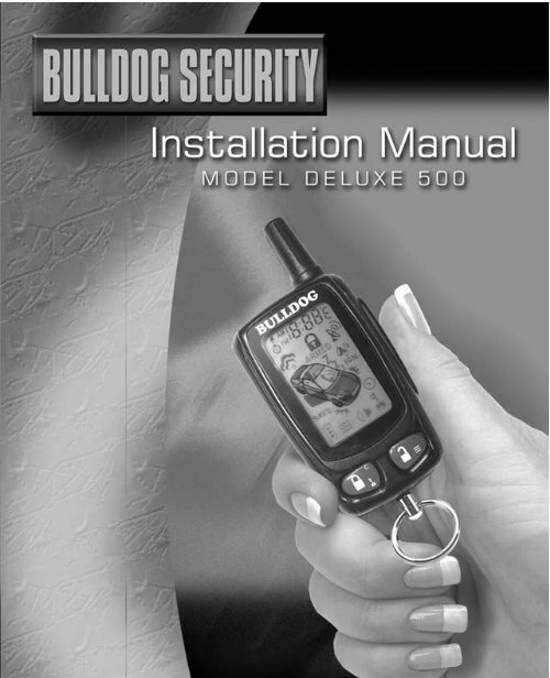
• 1- Main Control Module<br />
• 1- Five Button LCD Remote<br />
Transmitter<br />
• 1- 6 Pin Ignition Harness<br />
• 1- 5 Pin Harness<br />
• 1- 10 Pin Mini Output Harness<br />
• 1- 9 Pin Mini Input Harness<br />
• 1- 2 Pin Valet Switch<br />
• 1- 2 Pin Led Light Harness<br />
• 1- 4 Pin Antenna Harness<br />
• 1- 6 Pin Door Lock Harness<br />
• 1- Hood Switch<br />
• 1- Hood and Window Decal<br />
• 1- Installation Manual<br />
• 1- Owners Manual<br />
6
.<br />
INSTALLATION DIAGRAM<br />
6<br />
6 Pin White<br />
Connector for<br />
Door Lock and<br />
Door Unlock<br />
Connection<br />
7
.<br />
WIRING HARNESSES<br />
Keep all wiring away from moving engine parts, exhaust pipes and hightension<br />
cable. Tape wires that pass through holes on the firewall to prevent<br />
fraying. Watch out for sharp edges that may damage wires and cause<br />
short circuits.<br />
CAUTION: Do not connect the wire harness to the control<br />
module until all wiring to vehicle is complete.<br />
8
. .<br />
WIRING CONNECTIONS<br />
H1: 6-PIN HEAVY GAUGE WIRING CONNECTIONS:<br />
Remember that the system is designed to duplicate the same functions<br />
of the ignition key switch! Since this installation will require analysis of<br />
the ignition switch functions, we recommend making the H1 harness<br />
connections directly to the ignition switch wires.<br />
H1/1 VIOLET Wire—(Starter Crank Output)<br />
Connect the VIOLET wire to the starter crank wire at the ignition switch<br />
harness. This wire show +12 volts when the ignition switch is turned<br />
to the “start” or “crank” position only. This wire will test 0 volts in all<br />
other ignition switch positions.<br />
H1/2 and H1/3 RED Wires (2)-(+12V Power Input)<br />
Remove the two 20A fuses prior to connecting these wires and do not<br />
replace them until the satellite harness has been plugged into the control<br />
module. These two wires are the source of current for all the circuits the<br />
relay satellite will energize. They must be connected to a high current<br />
source. Since the factory supplies (+) 12V to the key switch, it is<br />
recommended you make your connections there.<br />
Note: If the factory supplies two separate (+) 12V feeds to the ignition<br />
switch, connect one RED wire of the satellite to each feed at the switch.<br />
H1/4 YELLOW Wire – (Ignition 1 Output)<br />
Connect the YELLOW wire to the ignition one wire from the ignition<br />
switch. The ignition wire should receive "12 volts" when the ignition<br />
key is in the "on" and "start" or “crank” positions. When the ignition<br />
is turned "off", the ignition wire should receive "0" voltage. The YELLOW<br />
wire must be connected.<br />
H1/5 PINK Wire – (Ignition 2 Output)<br />
Some vehicles have 2 ignition wires that must be connected. Attach the<br />
PINK wire to the ignition 2 wire from the ignition switch. The ignition<br />
wire should receive "+12 volts" when the ignition key is in the "on" or<br />
“run” and "start" or “crank” positions. When the ignition is turned to<br />
the"off" position this wire will show "0" voltage. If the PINK wire is<br />
not used, cap or tape the end of the wire.<br />
9
.<br />
WIRING CONNECTIONS<br />
H1/6 BROWN Wire –Accessory Output (Heater /AC Output)<br />
Connect the BROWN wire to the Accessory/Heater-Blower wire in the<br />
vehicle that powers the Heater/AC system. The Accessory/Heater-Blower<br />
wire will show “+ 12 volts” when the ignition switch is turned to the<br />
“accessory”(some vehicle) “on” and “run” positions, and will show<br />
“0” volts when the key is turned to the “off” and “start” or “crank”<br />
positions. On some vehicles, there will often be more than one<br />
Accessory/Heater-Blower wire in the ignition harness. The correct<br />
Accessory/Heater-Blower wire will power the vehicle’s Heater/AC system.<br />
Note: Some vehicle may have separate wires for the blower motor and<br />
the air conditioning compressor such as Ford products. In such cases,<br />
it will be necessary to add a relay to power the second Accessory/Heater-<br />
Blower wire, if your vehicle does not have a Ignition 2 wire, use the<br />
Ignition 2 Output (H1/5 PINK) wire from the remote starter to power<br />
up the second Accessory/Heater-Blower wire.<br />
H2: 5-PIN WIRE HARNESS:<br />
H2/1 RED / WHITE Wire (Parking Light Relay Input)<br />
The RED/WHITE wire is the input for the parking light relay. This<br />
wire will determine the output polarity of the parking light relay.<br />
If your vehicle requires +12volts to power the parking light circuit you<br />
will not need to connect this wire. This wire is already connected to the<br />
+12 volt constant RED wire in the same harness.<br />
If your vehicle’s parking light circuit operates on a switched (-) negative<br />
ground then cut the RED/WHITE wire from the RED wire and attach<br />
it directly to a ground source. Note: Make sure to tape the RED wire<br />
at the cut location.<br />
H2/2 WHITE Wire (Parking Light Relay Output)<br />
Connect the WHITE wire to the wire that powers the parking light<br />
circuit on the vehicle. The WHITE parking light wire is rated at 10amps<br />
max and should not exceed this current. If your vehicles parking light<br />
system requires more then 10amps you must add a relay to power<br />
the parking light system.<br />
H2/3 BLACK Wire (System Ground)<br />
This is the main ground connection of the control module. Make this<br />
connection to a solid section of the vehicles frame ground.<br />
10
.<br />
WIRING CONNECTIONS<br />
H2/4 BROWN Wire (Horn Output)<br />
The BROWN wire will provide a (-) negative output for the vehicles<br />
horn or optional siren hookup.This wire is a transistorized low current<br />
200mA output, and should only be connected to the low current ground<br />
output from the vehicle's horn switch.<br />
H2/5 RED Wire (System +12volt Constant Power)<br />
Connect the RED wire to a constant +12 volt source.<br />
H3: 4-PIN BLACK CONNECTOR (Windshield Receiver / Antenna)<br />
The windshield receiver/antenna mounts on the inside of the front windshield.<br />
We suggest you mount it on the lower left or upper left-hand side of<br />
windshield.<br />
Warning! Do not mount in such a manner that it obstructs the driver’s<br />
view.<br />
- The receiver/antenna whip must be vertical.<br />
- Remove the protective tape backing and clean the are around the glass<br />
where you are installing.<br />
- Carefully align the receiver/antenna and apply to windshield.<br />
- Route the black connector wire behind the trim and connect to<br />
receiver/antenna.<br />
- Connect the other end to the control module.<br />
- Special considerations must be made as some newer vehicles utilize<br />
a tinted window glass that can effectively reduce the range.<br />
H5 9-PIN BLACK WIRING HARNESS:<br />
H5/1 GREY Wire (-) (Negative Safety Shut Down For Hood Switch)<br />
This wire provides an instant shutdown for<br />
the remote start, whenever it is grounded.<br />
Connect the wire to the hood pin switch<br />
previously installed. This wire must be<br />
routed though a grommet in the firewall<br />
and connected to the hood pin switch.<br />
If the pin switch is to be used with an<br />
alarm system, connect this wire with diode.<br />
11
.<br />
WIRING CONNECTIONS<br />
H5/2 BROWN/RED (Positive Safety Shut Down or Brake Input)<br />
This wire provides an instant shutdown for the remote starter whenever<br />
it recieves a +12volts.Connect this wire to the output or cold side of<br />
the brake switch that shows +12volts only when the brake is pressed.<br />
See below diagram<br />
This wire provides an instant shutdown for<br />
the remote start, whenever it receives<br />
+12volts. If the brake lights switch in the<br />
vehicle switches +12 volts to the brake light circuit,<br />
connect this wire to the output side of the brake<br />
switch. This will allow the remote start to shut<br />
down if an attempt is made to operate the vehicle without<br />
the key while running under the control of the remote start. In most vehicles,<br />
in order to shift gear, the brake pedal must be depressed. The brake input<br />
will in turn cause the remote start unit to shut off. (See diagram.)<br />
Manual Transmission: When you are in manual transmission gear mode,<br />
you also need to connect the BROWN / RED wire into the handbrake switch.<br />
An isolation diode must be used for handbrake switched light circuits and<br />
brake light circuit. Most handbrake wire will show +12V at rest when the<br />
ignition is on and ground when you set the handbrake. However, if the<br />
handbrake wire shows 0V while the handbrake is at rest, you will need to<br />
add a relay as below.<br />
12
. .<br />
WIRING CONNECTIONS<br />
H5/3 THIN BLACK Wire ( Remote Start Enable or Nuetral Safety<br />
Input)<br />
When the THIN BLACK wire is grounded, the remote start unit is<br />
operable. When this wire is open from ground, the remote starter is<br />
disabled.<br />
1. The optional “remote start toggle switch” can be added on to this wire<br />
to temporally disable the remote starter. This feature is useful if the<br />
vehicle is being serviced or stored in an enclosed area.<br />
2. This wire can also be connected to the neutral safety switch wire in<br />
the vehicle.<br />
IMPORTANT NOTE: Directly connect the THIN BLACK wire to<br />
ground when not being used. The remote starter will not start if<br />
this wire is not grounded.<br />
H5/4 BLUE / WHITE Wire (Not Used)<br />
H5/5 GREY/BLACK (Negative Diesel Wait to Start Input)<br />
The GREY/BLACK wire is a (-) negative input for diesel vehicles only.<br />
This wire will attach directly to the wait to start bulb on the dashboard,<br />
or on some vehicles the ECM module. You must locate and test the wire<br />
that will provide a ground signal when the wait to start light is on. The<br />
correct wire will provide a (-) negative ground signal when the bulb is<br />
on and +12volts positive when the bulb is out. There are some vehicles<br />
that will have the opposite configuration and you will need to wire a relay<br />
to convert the polarity. (See diagram example below)You must program<br />
the control module for diesel mode. (See programming instructions.)<br />
H5/6 GREEN (Negative Door Input) (Must be used for manual<br />
transmissions)<br />
The GREEN wire is the (-) negative ground trigger input for negative style<br />
door circuits. This green wire will attach to the wire in the vehicle that<br />
provides a (-) negative ground when any of the doors are opened. The<br />
same wire in the vehicle will provide +12volts positive or 0 voltage when<br />
the doors are closed.<br />
13
.<br />
WIRING CONNECTIONS<br />
H5/7 VIOLET (Positive Door Input) (Must be used for manual<br />
transmissions)<br />
The VIOLET wire is the positive trigger input for +12volt positive style<br />
door circuits. The VIOLET wire will attach to the wire in the vehicle that<br />
provides +12volt positive when the door is opened. The same wire in<br />
the vehicle will provide 0 voltage or negative ground when the doors<br />
are closed. This type of door circuit is most common with Ford vehicles.<br />
H5/8 WHITE/BLACK (Instant Start and Stop Input)<br />
The WHITE/BLACK wire will activate and deactivate the remote starter<br />
when it sees a momentary (-) negative ground.<br />
This wire is used for testing purposes and to activate the remote starter<br />
from another source. (See Alarm Feature #3 Programming Chart)<br />
H5/9 VIOLET / WHITE Wire (Tach. Input or Oil Sensor Connection)<br />
(Tach Input Connection)<br />
Note: No connection of this wire is required, if you are using the voltage<br />
checking type mode. This input provides the remote start system with<br />
information about the engine’s revolutions per minute (RPM). It can be<br />
connected to the (-) negative side of the coil in vehicle with conventional<br />
coils. To test for a tachometer wire, a multi-meter capable of testing AC<br />
voltage must be used. The tach wire will show between 1V and 6V AC<br />
at idle, and will increase as the engine RPM increases. In multi-coil ignition<br />
systems, the control module can learn individual coil wires.<br />
IMPORTANT! Do not test for tach wires with a test light or logic probe.<br />
How to find a tach wire with your multi-meter<br />
1. Set the ACV or AC voltage (12V or 20V is fine.)<br />
2. Attach the (-) probe of the meter to chassis ground.<br />
3. Start and run the vehicle.<br />
4. Probe the wire you suspect of being the tach wire with the red probe of<br />
the meter.<br />
5. If this is the correct wire the meter will read between 1V and 6V.<br />
IMPORTANT NOTE: You must program the “Tach Signal” before<br />
trying to remote start.<br />
Oil Sensor Signal Connection<br />
Locate the wire connected to the oil sensor.<br />
Negative Oil Sensor Connections: +12volts to +14volts will show on<br />
the multimeter when the ignition switch is turned to the “ON” position in<br />
the key cylinder and +2volts to + 3volts when the motor is running. 14
.<br />
WIRING CONNECTIONS<br />
Positive Oil Sensor Connections: +2volts to + 3volts will show “ON”<br />
the multimeter when the ignition switch is turned to the “on” position in the<br />
key cylinder and +12volts to + 14volts when the motor is running.<br />
IMPORTANT NOTE: You must program for oil sensing type before<br />
trying to remote start. (See programming start feature #2.)<br />
H6: 6-PIN DOOR LOCK CONNECTOR:<br />
15
.<br />
WIRING CONNECTIONS<br />
VACUUM OPERATED DOOR<br />
LOCKING SYSTEM:<br />
TYPICAL OF MERCEDES BENZ<br />
AND AUDI.<br />
Locate the wire under the driver's<br />
kick panel. Use the voltmeter<br />
connecting to ground, verify that<br />
you have the correct wire with the<br />
doors unlocked, the voltmeter will<br />
receive "12 volts". Lock the doors<br />
and the voltmeter will read "0 volt".<br />
Move the alligator clip to +12V and<br />
the voltmeter will receive "+12 volts". Cut this wire and make your<br />
connections. Be sure to program the door lock timer for 3.5 seconds.<br />
16
. .<br />
WIRING CONNECTIONS<br />
H7: 10-PIN WHITE WIRING HARNESS:<br />
H7/1 BLUE / BLACK Wire (Ignition 3 Output)<br />
This wire provides a 200mA (-) negative ground output that becomes<br />
active 4 seconds before the remote start unit initializes, and remains<br />
grounded while running.<br />
Ignition 3 output:<br />
Some newer vehicles use a<br />
third ignition wire which is<br />
required to start and keep<br />
the vehicle’s engine running.<br />
If this is the case, wire an<br />
IGN 3 relay (not supplied) as<br />
shown: Do not connect<br />
any vehicle circuits together, they<br />
are isolated for a reason.<br />
H7/2 BLACK/VIOLET (Timer Control Channel 6 Programmable<br />
Output)<br />
The BLACK/VIOLET wire provides a 200mA (-) programmable (-)<br />
negative ground output for a variety of optional devices. The output on<br />
the BLACK/VIOLET wire is programmable from 1 to 120 seconds. (See<br />
Alarm Feature #3 Programming Chart.)<br />
This wire can be used to open a sunroof, or any power device you choose<br />
to control. The BLACK/VIOLET wire must be wired to a relay when<br />
powering any devices.<br />
Note: factory default setting is a 1 second momentary (-) negative<br />
ourput. (See Alarm Feature #3 Programming Chart.)<br />
To activate this feature press the transmitter and buttons at the<br />
same time.<br />
H7/3 BROWN/BLACK (Factory Rearm Output)<br />
The BROWN/BLACK wire provides a 200mA (-) negative output for<br />
hooking up to the vehicles factory rearm wire. For factory rearm a (-)<br />
negative pulse is provided after the remote starter times out or is shut<br />
down with the transmitter.<br />
17
. .<br />
WIRING CONNECTIONS<br />
H7/4 BLACK/WHITE (Dome Light Supervision Output)<br />
The BLACK/WHITE wire provides a 200mA (-) negative output for 30<br />
seconds when the doors are unlocked using the transmitter. The<br />
BLACK/WHITE wire will also flash the dome light circuit for the same<br />
duration as the siren when violated. Note: If not attaching the<br />
BLACK/WHITE wire directly to the BCM (Body control module) a<br />
relay must be used to power the dome light circuit.<br />
H7/5 BLACK/RED (Timer Control Channel 5 Programmable Output)<br />
The BLACK/RED wire provides a 200mA (-) negative programmable<br />
ground output for a variety of optional devices. The output on the<br />
BLACK/RED wire is programmable from 1 to 120 seconds. (See Alarm<br />
Feature #3 Programming Chart)<br />
This wire can be used to open a sunroof, or any power device you choose<br />
to control. The BLACK/RED wire must be wired to a relay when powering<br />
any devices. Note: factory default setting is a 1 second momentary<br />
ground. (See Alarm Feature #3 Programming Chart)<br />
To activate this feature press the transmitter and buttons at the<br />
same time.<br />
H7/6 VIOLET/BLACK (Timer Control Channel 4 / Key Sensor Output)<br />
The VIOLET/BLACK wire provides a 200mA (-) negative programmable<br />
ground output for a variety of optional devices. The output on the<br />
black/violet wire is programmable from 1 to 120 seconds. (See Alarm<br />
Feature #3 Programming Chart)<br />
This wire can be used to open a sunroof, or any power device you choose<br />
to control. The VIOLET/BLACK wire must be wired to a relay when<br />
powering any devices.<br />
Note: factory default setting is a 1 second momentary ground.<br />
(See Alarm Feature #3 Programming Chart)<br />
Note: this wire can also be programmed as a second start crank<br />
output. . (See Alarm Feature #3 Programming Chart)<br />
Some vehicles require a second starter wire to be energized, or on certain<br />
GM vehicles what is known as the bulb check wire must receive a ground<br />
signal while the starter is cranking. When using this wire as a second<br />
start wire (Most Nissan vehicles) a relay must be used to energize this<br />
circuit. Press the transmitter and buttons at the same time.<br />
18
.<br />
WIRING CONNECTIONS<br />
H7/7 RED/WHITE (Channel 3 Trunk Output)<br />
The RED/WHITE wire will provide a 1 second 200mA (-) negative<br />
ground pulse output by activating channel 3 on the transmitter for 2<br />
seconds. This feature will allow trunk release or other optional devises<br />
by remote transmitter. Note: If not attaching the RED/WHITE wire<br />
directly to the BCM (Body control module) a relay must be used<br />
to power the trunk or device being energized.<br />
H7/8 LT. GREEN / BLACK Wire ( Step 2 Door Unlock / Factory<br />
Disarm / Shock sensor Bypass)<br />
Dual Pulse Door Unlock Output –<br />
The dual pulse door unlock feature will work for the most fully electronic<br />
door lock circuits. When wired for this feature, pressing the disarm (or<br />
unlock) button one time will disarm the alarm and unlock the driver's<br />
door only. If you press disarm (or the unlock) button two times within<br />
3 seconds, the alarm will disarm and all the doors will unlock. (See Alarm<br />
Feature #3 Programming Chart.)<br />
Factory Security Disarm Signal Output – (Factory Default Setting)<br />
This wire is designed to disarm a factory installed security system. This<br />
wire sends a (-) negative 1 second pulse upon a remote start and remote<br />
door unlocking. Some factory systems must be disarmed to allow remote<br />
starting. In most cases, this wire may be connected directly to the factory<br />
alarm disarm wire. The correct wire will show nagative ground when the<br />
key is used to unlock the doors or trunk. This wire is usually found in the<br />
kick panel area in the wiring harness coming into the car body from the<br />
door. (See Alarm Feature #3 Programming Chart)<br />
Start Status (Shock Sensor By-Pass Control) Output–<br />
This wire is designed to by-pass a shock sensor module. This wire will<br />
supply an output at all times the remote start is operating plus an<br />
additional 3 seconds after the remote start unit turn off. (See Alarm<br />
Feature #3 Programming Chart.)<br />
19
.<br />
WIRING CONNECTIONS<br />
7/9 ORANGE/WHITE (Ground Output When Disarmed)<br />
The ORANGE/WHITE wire provides a 200mA (-) negative output<br />
when the security system is disarmed. This output can be used for<br />
activating optional devises such as memory positions for power seats.<br />
Note: If not attaching the orange/white wire directly to the BCM<br />
(Body control module) a relay must be used to power the device<br />
being energized.<br />
H7/9<br />
H7/10 Orange (Starter Disable Relay Output)<br />
The ORANGE will provide a 500mA (-) negative output when the security<br />
system is armed. A relay with a diode across the coil must be used when<br />
interrupting the starter wire. If attaching more then one device to this<br />
wire you must diode isolate each device.<br />
H7/10<br />
H8: 2-PIN BLUE CONNECTOR FOR THE PROGRAM / VALET SWITCH:<br />
Select a mounting location for the switch that is hidden but easily<br />
accessible to the driver of the vehicle. Mount the valet switch in a hidden<br />
but accessible location. Route and plug in the valet switch wires to the<br />
control module.<br />
H9: 2-Pin White Connector<br />
The LED light should be mounted in a highly visible location in the dashboard,<br />
center console or dashboard face. Provide for at least a 6mm space behind<br />
the LED light. Once a suitable location is chosen, drill a 6mm hole then<br />
press the LED housing into the hole. Route the LED wires to the control<br />
module and plug it in.<br />
20
.<br />
PROGRAMMING AND TESTING<br />
A. Manual Transmission: When you are in manual transmission gear<br />
mode, you also need to connect the Brown / Red wire to the emergency<br />
or handbrake switch. An isolation diode must be used for handbrake circuit<br />
and brake light circuit. Most handbrake wires will show +12V at rest when<br />
the ignition is on and ground when you set the handbrake. However, if the<br />
handbrake wire shows 0V while the handbrake is at rest, you will need to<br />
add a relay as shown in the diagram below.<br />
Automatic transmission gear vehicle: Uncut (leave intact) the “Violet<br />
Loop Wire”.<br />
Manual transmission gear vehicle: Cut the “Violet Loop Wire” and<br />
tape the end.<br />
Note: The system is not recommended for the manual transmission gear<br />
vehicles with removable tops.<br />
Note: When installing this system on a vehicle with manual transmission<br />
the following must be hooked up:<br />
1. “Brake Light Circuit” and “Handbrake Circuit”. (See H5/2<br />
BROWN/RED wire connection.)<br />
2. Negative door pin switch (see H5/6 GREEN wire connection.) or positive<br />
door pin switch (see H5/7 VIOLET wire connection.)<br />
Note: Vehicles with a manual transmission gear must use “Engine<br />
Checking Tach.” Or “Engine Checking Oil Sensor.” only. (See Start<br />
Feature Programming # 2 - 2)<br />
B. PROGRAMMING A NEW TRANSMITTER:<br />
Note: The control module will only retain the last 4 remote transmitters<br />
programmed. If the transmitter memory is exceeded, the security system<br />
will start deleting transmitters from memory in chronological order.<br />
1. Turn the Ignition switch from “OFF” to “ON” 3 times and stay in the<br />
“ON” position.<br />
2. Within 15 seconds, push the valet/program switch 3 times and on<br />
the 3rd push hold it in until a long chirp from horn and the LED start<br />
to flash then release the valet/program switch. You are now in the<br />
transmitter programming mode.<br />
3. Press and hold any button on the transmitter until (1) chirp from the<br />
horn and (1) flash from the parking lights confirming the first transmitter<br />
is now programmed.<br />
4. If you have additional transmitters (up to 4) that need to be programmed,<br />
repeat step 3 for each transmitter.<br />
21
. .<br />
PROGRAMMING AND TESTING<br />
Exit: Turn the ignition switch to the “OFF” position, or leave it for 15<br />
seconds. 3 long chirps and 3 parking light flashes will confirm<br />
programming exit.<br />
C. FEATURES PROGRAMMING:<br />
ALARM FEATURE. #1 PROGRAMMING:<br />
1. Turn the Ignition switch from “ON” to “OFF” 3 times and stay in the<br />
“OFF” position.<br />
2. Push the programming switch 2 times and on 2 nd push hold it until<br />
(1) chirp followed with a long chirp is heard, then release the switch.<br />
You are now in the “alarm feature #1 programming mode”.<br />
3. Press and release the transmitter button that corresponds to the feature<br />
you desire to program.<br />
a. The amount of horn chirps and LED pause will indicate the previous<br />
setting.<br />
b. The factory default settings will always be [1] LED flash and [1]<br />
horn chirp.<br />
4. Press the transmitter button again to change the feature. Simply keep<br />
re-pressing the transmitter button until the module advances to your<br />
desired programming setting.<br />
Example:<br />
a. After you hear (1) chirp, press the button again and the module will<br />
advance to [2] LED flashes and [2] horn chirps.<br />
b. Press the button again, the module will advance to [3] LED flash<br />
and [3] horn chirps etc.<br />
ALARM FEATURE #1 PROGRAMMING CHART<br />
One Chirp with<br />
Press One LED Pulse<br />
Transmitter Factory Default Two Chirps with Three Chirps with Four Chirps with<br />
Button Setting Two LED Pulses Three LED Pulses Four LED Pulses<br />
1 Chirps off Chirps on<br />
2 Active arming Passive arming Passive arming Active arming<br />
without passive with passive with Passive<br />
door locking door locking starter disable<br />
3 Automatic Automatic<br />
Rearm off Rearm on<br />
22
.<br />
PROGRAMMING<br />
ALARM FEATURE #1 PROGRAMMING CHART<br />
One Chirp with<br />
Press One LED Pulse<br />
Transmitter Factory Default Two Chirps with Three Chirps with Four Chirps with<br />
Button Setting Two LED Pulses Three LED Pulses Four LED Pulses<br />
4 45 Second Instant<br />
Delay Door Door Ajar<br />
Ajar Warning Warning<br />
5 + Panic with Panic with Panic with Without Panic<br />
Ignition off Ignition Ignition function<br />
on and off on and off.<br />
Panic with no<br />
time limit<br />
Exit: Turn ignition switch to the on position, or leave it for 15 seconds. 3<br />
long chirps and 3 parking light flashes will confirm programming exit.<br />
DOOR AJAR WARNING (45 SECOND DELAY):<br />
This feature controls the error chirp that is generated if the system is armed<br />
with the door trigger active. This is useful in a vehicle that has a dome light<br />
delay after the door has been closed. If the system is armed before the<br />
dome light has turned “OFF”, the security system will generate the door<br />
trigger error chirp. Use this feature to disable the door open error chirp<br />
ALARM FEATURE. #2 PRORAMMING:<br />
1. Turn the Ignition switch from “ON” to “OFF” 3 times and stay in “OFF”<br />
position.<br />
2. Push the valet/program switch 4 times and hold the 4 th push in until<br />
(2) chirps followed with (1) long chirp is heard then release the<br />
valet/program switch. You are now in the “alarm feature #2<br />
programming mode”.<br />
3. Press and release the transmitter button that corresponds to the feature<br />
you desire to program.<br />
23
.<br />
PROGRAMMING<br />
ALARM FEATURE #2 PROGRAMMING CHART<br />
One Chirp with<br />
Press One LED Pulse<br />
Transmitter Factory Default Two Chirps with Three Chirps with Four Chirps with<br />
Button Setting Two LED Pulses Three LED Pulses Four LED Pulses<br />
1 0.9-second 3.5-second Double pulse Door lock with<br />
door lock pulse door lock pulse unlock “Comfort Feature”<br />
2 Ignition Ignition Ignition Without ignition<br />
controlled door controlled door controlled door controlled door<br />
lock and unlock lock only unlock only lock and unlock<br />
3 Pathway Parking light Parking light turns<br />
illumination turns “on” for “on” for 30-seconds<br />
feature “off” 30-seconds upon upon and unlock<br />
an unlock signal signal & 10-seconds<br />
upon a lock signal<br />
4 Disable the out Enable the out<br />
of range check of range check<br />
Exit: Turn ignition switch to the “ON” position, or leave it for 15 seconds.<br />
3 long chirps and 3 parking light flashes will confirm programming exit.<br />
Comfort Feature:<br />
Some vehicles have a special comfort feature. When you lock the driver’s<br />
door with the key, and hold the key in the door for 5 to 7 seconds all the<br />
windows in the vehicle will roll up. If you would like to operate this feature<br />
with the remote transmitter, you can program the alarm feature # 2-1 to<br />
“Comfort Feature”.<br />
ALARM FEATURE. # 3 PRORAMMING:<br />
1. Turn the Ignition switch “ON” to “OFF” 3 times and stay in “OFF”<br />
position.<br />
2. Push the valet/program switch 6 times and hold it in on the 6 th push<br />
until 3 chirps followed with a long chirp is heard and the LED turns on<br />
then release the valet/program switch. You are now in the Alarm<br />
feature # 3 programming mode.<br />
3. Press and release the transmitter button that corresponds to the feature<br />
you desire to program.<br />
24
.<br />
PROGRAMMING<br />
ALARM FEATURE #3 PROGRAMMING CHART<br />
One Chirp with<br />
Press One LED Pulse<br />
Transmitter Factory Default Two Chirps with Three Chirps with Four Chirps with<br />
Button Setting Two LED Pulses Three LED Pulses Four LED Pulses<br />
1<br />
2 H7/8 Lt. Green/ H7/8 Lt. Green/ H7/8 Lt. Green/<br />
Black Wire= Black Wire= Black Wire= Start<br />
Factory Security Dual Pulse Door Status Output<br />
Disarm SignalUnlock (Shock Sensor<br />
Output<br />
Bypass)<br />
3 H5/8 White/ H5/8 White/ H5/8 White/Black<br />
Wire=1 Pulse Wire= 2 Pulses Wire= 3 Pulses<br />
Activate Activate Activate<br />
4<br />
5 + H7/6 Violet/ H7/6 Violet/ H7/6 Violet/ H7/6 Violet/<br />
Black Wire Black Wire Black Wire Black Wire<br />
Channel 4 Output= Channel 4 Output= Channel 4 Output= Channel 4 Output=<br />
Momentary Latched Output Latched output & Timer programm-<br />
Output reset with ignition ing (set to any<br />
“on”<br />
interval between<br />
1 sec. and 2 min.)<br />
6 + H7/5 Black/Red H7/5 Black/Red H7/5 Black/Red H7/5 Black/Red<br />
Wire Channel 5 Wire Channel 5 Wire Channel 5 Wire Channel 5<br />
Output = Output= Output= Output=<br />
Momentary Output Latched Output Latched output and Timer programmreset<br />
with ignition<br />
“on”<br />
ing (set to any<br />
interval between<br />
1 sec. and 2 min.)<br />
7 + H7/2 Black/ H7/2 Black/ H7/2 Black/ H7/2 Black/<br />
Violet Wire Violet Wire Violet Wire Violet Wire<br />
Channel 6 Output= Channel 6 Output= Channel 6 Output= Channel 6 Output=<br />
Momentary Output Latched Output Latched Output and Timer programmreset<br />
with ignition ing (set to any<br />
Exit: Turn ignition switch to the on position, or leave<br />
“on”<br />
interval between<br />
it for 15 seconds. 3 long chirps and 3 parking light<br />
1 sec. and 2 min.)<br />
flashes will confirm programming exit.<br />
25
.<br />
PROGRAMMING<br />
Channels 4 (5 / 6) Timer Control Output Programming.<br />
1. Turn the Ignition switch from “ON” to “OFF” 3 times and stay in “OFF”<br />
position.<br />
2. Push the valet/program switch 6 times and hold it in on the 6 th push<br />
until 3 chirps followed with (1) long chirp is heard and the LED turns<br />
on then release the valet/program switch. You are now in the “alarm<br />
feature # 3 programming mode”.<br />
3.-a. Press and release the transmitter and buttons together 4 times,<br />
[4] LED flashes and [4] siren or horn chirps will indicate you are in<br />
“Channel 4 Timer Programming mode”.<br />
3-b. Press and release the transmitter and buttons together 4 times,<br />
[4] LED flashes and [4] siren or horn chirps will indicate you are in<br />
“Channel 5 Timer Programming mode”.<br />
3-c. Press and release the transmitter and buttons together 4 times,<br />
[4] LED flashes and [4] siren or horn chirps will indicate you are in<br />
“Channel 6 Timer Programming mode”.<br />
4. Press and hold the valet/program switch, the timer will immediately start.<br />
5. When the desired interval has passed, release the valet/program<br />
switch. (1) long chirp for confirmation. (Set to any interval between<br />
1 second and 2 minutes)<br />
Note 1:<br />
If your built-in timer controls windows or a sunroof in your vehicle DO NOT<br />
change the timer setting! This requires installer-only programming. Changing<br />
the value will adversely effect operation and may cause damage.<br />
Note 2:<br />
Momentary output The momentary output selection will provide a negative<br />
signal from the Channel 4 (5/6) output immediately when the Channel<br />
4 (5/6) button is pressed and will continue until the button is released.<br />
Latched output The latched output selection will provide a negative signal<br />
as soon as the Channel 4 (5/6) button is pressed and will continue until<br />
the button is pressed again<br />
Latched output / reset with ignition The latched / reset with ignition<br />
output selection operates just like the latched output but will reset or stop<br />
when the ignition is turned on.<br />
Ground Output During Start (Crank) This wire will provide a 200 mA<br />
ground output while the starter output of the remote start unit is active.<br />
This output can be used to activate the Crank Low/Bulb Test wire found in<br />
some GM vehicles. This wire is also referred to as the ECM wake up wire<br />
in some vehicles.<br />
26
.<br />
PROGRAMMING<br />
REMOTE START FEATURE PROGRAM MODE.<br />
START FEATURE. # 1 PRORAMMING:<br />
1. Turn the Ignition from “ON” to “OFF” 3 times and stay in “OFF” position.<br />
2. Push the valet switch 8 times and hold it in on the 8 th push until (4)<br />
chirps followed with (1) long chirp is heard and the LED turns on then<br />
release the valet/program switch. You are now in the “start feature<br />
#1 programming mode”.<br />
3. Press and release the transmitter button that corresponds to the feature<br />
you desire to program.<br />
START FEATURE CHART #1<br />
One Chirp with<br />
Press One LED Pulse<br />
Transmitter Factory Default Two Chirps with Three Chirps with Four Chirps with<br />
Button Setting Two LED Pulses Three LED Pulses Four LED Pulses<br />
1 + Gasoline Engine<br />
Diesel Engine Diesel Engine Diesel Engine Diesel Engine<br />
with Wait-to- without Wait-to without Wait-to without Wait-to<br />
Start Light Start Light 10 Start Light 15 Start Light 20<br />
(H5/5 Grey/ seconds warm-up seconds warm- seconds warm-up<br />
Black Wire must timer up timer timer<br />
be connected)<br />
2 20 Minute 30 Minute 5 Minute 10 Minute<br />
Run Time Run Time Run Time Run Time<br />
3 Factory Alarm Without this<br />
Disarm with Feature<br />
Channel 3 On<br />
4 Constant Flashing Parking<br />
Parking Light Light Output<br />
Output<br />
5 Without this Door Lock Before Door Lock After Door Lock Before<br />
Feature Start Shut-Down Start and Door<br />
Lock After Shut-<br />
Down<br />
27
. .<br />
PROGRAMMING<br />
One Chirp with<br />
Press One LED Pulse<br />
Transmitter Factory Default Two Chirps with Three Chirps with Four Chirps with<br />
Button Setting Two LED Pulses Three LED Pulses Four LED Pulses<br />
6 + Press - Press + Press button =<br />
Button=Activate Button=Activate Activate Remote<br />
Remote Start Remote Start Start<br />
7 + Fahrenheit Celsius Display<br />
Display for for Temperature<br />
Temperature<br />
8 + Temperature- Temperature- Temperature- Temperature-<br />
Control I Start- Control Starting Control Starting Control Starting<br />
ing OFF 5F (-15C) - 4F (-20C) - 22F (-30C)<br />
Exit: Turn Ignition to “ON” position, or leave it for 15 seconds. 3 long<br />
chirps and 3 parking light flashes to confirm exit.<br />
SAFE START (Child safety mode)<br />
Factory defaults setting to press the button twice to start the vehicle.<br />
Programming this feature to eliminate an accidental remote start, when<br />
kids enter this transmitter, it requires: The user press the transmitter and<br />
buttons at the same time to start the vehicle.<br />
START FEATURE. # 2 PRORAMMING:<br />
1. Turn the ignition switch from “OFF” to “ON” 3 times and stay in the<br />
“OFF” position.<br />
2. Push the valet/program switch 10 times and hold it in on the 10 th<br />
push until (5) chirps followed with (1) long chirp is heard and the<br />
then release the valet/program switch. You are now in the start<br />
feature #2 programming mode.<br />
3. Press and release the transmitter button that corresponds to the feature<br />
you desire to program.<br />
28
.<br />
PROGRAMMING<br />
START FEATURE CHART #2<br />
One Chirp with<br />
Press One LED Pulse<br />
Transmitter Factory Default Two Chirps with Three Chirps with Four Chirps with<br />
Button Setting Two LED Pulses Three LED Pulses Four LED Pulses<br />
1 Exit the programming mode. (3 long chirps and 3 parking light flashes<br />
to confirm this exit.)<br />
2 + Engine Checking Engine Checking Engine Checking Engine Checking<br />
Voltage TACH / RPM Negative Oil Positive Oil<br />
Learning Mode Sensor Sensor<br />
3 Start Timer: 0.8-second (2 chirps), 1.0-second (3 chirps) 1.2-second<br />
0.6-second (4 chirps), 1.4-second (5 chirps), 1.6-second (6 chirps),<br />
1.8-second (7 chirps), 2.0-second (8 chirps), 3.0-<br />
second (9 chirps), 4.0-second (10 chirps.<br />
4 Low check level Hi check level<br />
5 + Start or stop the system for TESTING AND ADJUSTMENT<br />
6 + 3 Hour Time 2 Hour Time<br />
Start<br />
Start<br />
7 + The Vehicle The Vehicle has Built-in Turbo Built-in Turbo<br />
without Turbo aftermarket Turbo Timer Control is Timer Control is<br />
(The system timer installed. Active. Press Active: Press<br />
cannot be The system + buttons at + buttons at<br />
Arm with the can be Arm with the same time the same time to<br />
engine is engine running to control control Engine<br />
running. and the shock engine running running three<br />
sensor will be by- one minute. minutes.<br />
pass as long as<br />
the engine is<br />
running.<br />
Five chirps=Built-in Turbo Timer Control is Active/Press<br />
and buttons at the same time to control Engine<br />
runningfive minutes.<br />
29
.<br />
PROGRAMMING<br />
Exit: Press the button on the transmitter 3 long chirps and 3 parking<br />
light flashes will confirm programming exit.<br />
IMPORTANT NOTE: You must program the “Tach Signal” before<br />
trying to remote start.<br />
ENGINE CHECKING TACH. / RPM LEARNING<br />
1. Turn the ignition switch from “OFF” to “ON” 3 times and stay in “OFF”<br />
position.<br />
2. Push the valet/program switch 10 times and hold it until five chirps<br />
followed with a long chirp is heard then release the valet/program<br />
switch.<br />
3. Press and release the transmitter and buttons at the same time<br />
twice [2] LED flashes and [2] chirps will confirm the system in features<br />
“RPM learning mode”.<br />
4. Within 10 seconds, start the vehicle with the key. (While the engine is<br />
running, the parking lights and LED light will flash, if they don’t, please<br />
check your VIOLET/WHITE wire connection.<br />
5. Press and hold the valet switch for 2 seconds until a long chirp and the<br />
LED light flashes constant for two seconds. The RPM signal is now learned.<br />
6. Turn off the ignition switch to stop the engine from running<br />
7. If the crank time on the starter needs adjusted proceed to crank level<br />
programming.<br />
CRANK TIME ADJUST / HI OR LOW LEVEL CHECK<br />
1. Press the button twice on the transmitter to start the vehicle.<br />
2. If everything goes well:<br />
a. Press the button twice on the transmitter to stop engine running.<br />
You have been completed this programming successfully.<br />
b. Press button on the transmitter to exit the program mode. There<br />
will be 3 long chirps and (3) parking light flashes for confirmation.<br />
3. If the crank time is too short, (Engine not running, before the starter<br />
stops cranking):<br />
a. Press the button twice on the transmitter to turn the ignition off.<br />
Press button on the transmitter to set proper “Check Level” to<br />
Hi position. [2] LED flashes and [2] chirps will confirm this setting.<br />
b. Repeat the step1 – 4.<br />
30
.<br />
PROGRAMMING<br />
4. If the crank time is too long, (Engine already successfully running, while<br />
the starter remains engaged):<br />
a. Press the button twice on the transmitter to stop the engine<br />
running. Press button on the transmitter to set proper “Check<br />
Level” to Low position. [1] LED flash and [1] chirp will confirm this<br />
setting<br />
b. Repeat the step1 – 4.<br />
ENGINE CHECKING VOLTAGE<br />
1. Turn the ignition switch from “ON” to “OFF” (3) times and stay in<br />
“OFF” position.<br />
2. Push the valet/program switch (10) times and hold it until (5)<br />
chirps followed by a long chirp is heard then release the valet/program<br />
switch.<br />
3. Press the transmitter and buttons at the same time to set the<br />
“Voltage Checking Type”. (2) LED flashes and (2) chirps will<br />
confirm this setting.<br />
Once you complete step 3, you can adjust and test “Start Timer” as<br />
below:<br />
START TIMER PROGRAMMING (TESTING AND ADJUSTING THE CRANK<br />
TIME)<br />
1. Press the button twice on the transmitter to start the vehicle.<br />
2. If everything goes well: Wait for 15 seconds:<br />
a. If the engine still running.<br />
I. Press the button twice on the transmitter to stop the engine<br />
from running. You have completed this programming successfully.<br />
II. Press button on the transmitter to exit the program mode.<br />
There will be 3 long chirps and (3) parking light flashes for<br />
confirmation.<br />
b. If the engine shut down after the vehicle has been started.<br />
I. Press the button twice on the transmitter to turn the<br />
ignition off.<br />
II. Press button on the transmitter to set “Check Level” to LOW<br />
position. [1] LED flash and [1] chirp will confirm this setting.<br />
III. Repeat the step1 – 2.<br />
31
.<br />
PROGRAMMING<br />
3. If the crank time is too long, (The engine is successfully running,<br />
while the starter is still cranking):<br />
a. Press the button twice on the transmitter to stop the engine.<br />
b. Press button on the transmitter to set proper “Start Timer”.<br />
The chirp and LED pauses will confirm you have entered the<br />
start timer mode (Decreasing the start timer is necessary.)<br />
c. Repeat the step1 – 4.<br />
4. If the crank time is too short, (The engine is not running and the<br />
starter did not engage long enough)<br />
a. Press the button twice on the transmitter to turn the ignition<br />
“OFF”.<br />
b. Press button on the transmitter to set proper “Start Timer”.<br />
The chirp and LED pauses will confirm you have entered the start<br />
timer mode. (Increasing the Start timer is necessary.)<br />
c. Repeat the step1 – 4.<br />
ENGINE CHECKING OIL SENSOR<br />
1. Turn the Ignition switch from “ON” to “OFF” 3 times and stay in “OFF”<br />
position.<br />
2. Push the valet/program switch 10 times and hold it in on the 10 th<br />
push until (5) chirps followed with (1) long chirp is heard and the LED<br />
turns on then release the valet/program switch.<br />
3. Press the transmitter and buttons at the same time to set the<br />
“Engine Checking Oil Sensor”. [3] / [4] LED flashes and [3] / [4]<br />
chirps will confirm this setting.<br />
Once you complete step 3, you can adjust and test “Start Timer” as below:<br />
START TIMER PROGRAMMING: (TEST and ADJUST)<br />
Press the button twice on the transmitter to start the vehicle.<br />
1. If everything goes well:<br />
a. Press the button twice on the transmitter to stop engine running.<br />
You have been completed this programming successfully.<br />
b. Press button on the transmitter to exit the program mode. There<br />
will be (3) long chirps and (3) parking light flashes for confirmation.<br />
32
.<br />
PROGRAMMING<br />
2. If the crank time is too long, (Engine already successfully running, while<br />
the starter is still cranking):<br />
a. Press the button twice on the transmitter to stop engine from<br />
running.<br />
b. Press the button on the transmitter to set proper the “Start Timer”.<br />
The chirp and LED pauses will confirm you are in the start timer mode.<br />
(Decreasing the Start Time is necessary.)<br />
c. Repeat the step1 – 4.<br />
3. If the crank time is too short (The engine is not running and the starter<br />
did not engage long enough)<br />
a. Press the button twice on the transmitter to turn off the ignition.<br />
b. Press button on the transmitter to set proper “Start Timer”. The<br />
chirps and LED pauses will confirm you are in the start timer mode.<br />
(Increasing the start timer is necessary.)<br />
c. Repeat the step1 – 4.<br />
RETURN TO FACTORY DEFAULT SETTING:<br />
Note: This will reset all alarm features to factory default settings<br />
1. Turn the ignition from “ON” to “OFF” (3) times and stay in the<br />
“OFF” position.<br />
2. Push the valet switch (12) times and hold it until (6) short chirps<br />
followed by a long chirp is heard.<br />
Press and hold the and buttons at the same time on the transmitter<br />
for 6 seconds, there will be a confirmation of (6)short chirps with (3)<br />
long chirps to confirm the system Alarm Features #1, #2 and #3<br />
programming all return to factory default settings.<br />
Note: This will reset all remote starter features to factory default<br />
settings<br />
1 Press the button first, within 3 seconds press and hold the and<br />
buttons at the same time on the transmitter for 6 seconds, there will<br />
be a confirmation of (6) short chirps followed by 3 long chirps to<br />
confirm the system “Start Feature #1 and #2 programming” will<br />
return to factory default settings.<br />
33
. .<br />
PROGRAMMING<br />
To Exit: Turn Ignition to the on position, or leave it for 15 seconds. 3<br />
long chirps and 3 parking light flashes will confirm programming exit.<br />
SHUTDOWN DIAGNOSTICS<br />
The unit has the ability to diagnose and report the cause of the last<br />
shutdown on the remote start system.<br />
Enter:<br />
1. Turn the Ignition switch to the “ON” position.<br />
2. Press the button on the transmitter.<br />
3. The LED will now report the last system shutdown by flashing for one<br />
minute in the following grouped patterns.<br />
LED<br />
Flashes Shutdown Mode<br />
1 (-) Safety Shutdown 1.Close the Hood<br />
Input (Hood)<br />
2.Check H5/1 GREY wire connection<br />
2 (+) Safety Shutdown Input 1.Set the Hand Brake (if installed)<br />
(Brake) or Hand Brake (if 2.Check H5/2 BROWN/RED wire<br />
installed or connection.<br />
Neutral Safety Switch 3.Move the Enable Toggle Switch to<br />
input fail “ON” position. (if installed)<br />
4.Move the gear selector to “Park”/<br />
“Neutral” position.<br />
5.Check H5/3 THIN BLACK wire<br />
connection.<br />
3 No RPM (Engine Checking Check H5/9 VIOLET/WHITE wire<br />
TACH) or<br />
connection.<br />
Low Voltage. (Engine Program the “CHECK LEVEL” from<br />
Checking Voltage) or “Hi Check Level” to “Low Check Level”<br />
Oil Sensor (Engine<br />
Check H5/9 VIOLET/WHITE wire<br />
Checking Oil Sensor) connection.<br />
4 Over-rev<br />
5 System timed out<br />
6 Transmitter<br />
34
.<br />
PROGRAMMING<br />
LED<br />
Flashes Shutdown Mode<br />
7 Tach. Signal has not been Re-learning the RPM (Start<br />
learned feature #2-2)<br />
8The procedure of the Check Operation Manual #<br />
Engine start memorizing Remote Start Operation B section.<br />
for the vehicle with manaul<br />
transmission gear is not completed.<br />
TESTING YOUR INSTALLATION<br />
Caution!! The follow procedure must be performed after the installation of<br />
the remote start device. It is the responsibility of the installing technician<br />
to complete these tests. Failure to test the unit in the following manner may<br />
result in personal injury, property damage, or both.<br />
1. Test the brake shutdown circuit: With the vehicle in park (P), start the<br />
vehicle using the remote transmitter. Once the engine is running, press<br />
the brake pedal. The vehicle should shut down immediately. If the vehicle<br />
continues to run, check the brake circuit BROWN/RED wire (H5/2)<br />
connection.<br />
2. Test the hood safety shutdown circuit: Start the vehicle using the remote<br />
transmitter. Once the engine is running, pull the hood release and raise the<br />
hood. The vehicle should shut down immediately. If the vehicle continues<br />
to run, check the hood pin GREY wire (H5/1) connection.<br />
NEUTRAL START SAFETY TEST:<br />
1. Set the vehicle parking brake.<br />
2. Block the drive wheels to prevent vehicle movement.<br />
3. Sitting in the vehicle, turn the ignition switch to on or run position,<br />
but do not start the engine.<br />
4. Step on the brake pedal and shift the gear selector into “DRIVE”<br />
(D).<br />
5. Put your foot over the brake pedal but do not press down on it. Be ready<br />
to step on the brake to shut down the remote start device.<br />
35
.<br />
TESTING YOUR INSTALLATION<br />
6. Start the vehicle using the remote transmitter.<br />
a. If the starter does not engage, the test is complete.<br />
b. If the starter engages, immediately step on the brake pedal to shut<br />
down the system and check your VIOLET wire H1/1 starter output<br />
connection. The heavy gauge VIOLET wire must be connected to the<br />
ignition switch side of the neutral safety switch. If the vehicle you are<br />
working on does not have an Electrical Neutral Safety Switch, it will be<br />
necessary to reconfigure the remote starts wiring to accommodate this<br />
vehicle. The information concerning the mechanical neutral safety switch<br />
provided below will help you to determine if the vehicle you are working<br />
on has this type of safety switch and will provide alternate wiring methods<br />
to accommodate this situation.<br />
MECHANICAL NEUTRAL SAFETY SWITCH CONSIDERATIONS:<br />
Mechanical neutral safety switch configurations differ slightly in that they<br />
do not offer the same level of safety when installing a remote start device.<br />
Often when the ignition switch is turned off while the gear selector is in any<br />
position other than park or neutral, the mechanical function will not allow<br />
the key to be turned to the start position or removed from the ignition<br />
cylinder. This configuration prevents mechanical operation while the vehicle<br />
is in gear but offers no consideration for the electrical operation. Because<br />
of this potential problem, your installation requires the additional connection<br />
of a safety wire from the remote start device to the vehicle PARK/NEUTRAL<br />
ECM input or the vehicle key in sensor wire. This connection will prevent<br />
remote start operation if the key is left in the ignition switch regardless of<br />
the gear selector position.<br />
PARK/NEUTRAL ECM INPUT:<br />
The Park/Neutral ECM input is the preferred method of installation. This not<br />
only maintains the integrity of the factory circuit but is also is the easiest<br />
to install, providing the vehicle you are working on has this ECM input.<br />
The installation required for this application (shown below), is a slight<br />
reconfiguration of the control switch wiring. Shown is a typical GM Park/Neutral<br />
ECM input circuit. To connect the remote start unit to the GM Park/Neutral<br />
ECM input:<br />
1. Locate the ORANGE/BLACK reference wire in the “C2” connector found<br />
at the ECM in GM B Body vehicles or, locate the equivalent reference<br />
wire in the vehicle you are installing the remote start unit in. 36
.<br />
TESTING YOUR INSTALLATION<br />
2. Connect the THIN BLACK Neutral Safety Switch wire (H5/3) to this<br />
reference wire.<br />
NOTE: If the optional remote starter enable toggle switch is installed,<br />
connect the one side of the switch to this reference wire the other side of<br />
to the THIN BLACK Neutral Safety Switch wire (H5/3) of the remote start<br />
unit. The reference diagram below shows a typical GM B Body ECM reference<br />
wire and how to connect it to the remote start unit.<br />
KEY IN SENSOR CIRCUITS:<br />
If the vehicle you are working on does not have or you cannot locate the<br />
ECM reference wire, there are two alternatives available. Although not<br />
preferred, the vehicle key in sensor may be reconfigured to allow a margin<br />
of safety and will prevent the vehicle with a mechanical neutral start switch<br />
from starting in gear.<br />
WE ADVISE THAT YOU MAINTAIN THE FACTORY CIRCUIT WHENEVER<br />
POSSIBLE. The following two circuits may be used only if the above circuit<br />
is not available.<br />
NOTE: When completing an installation using either of the following key in<br />
sensor circuits, if the operator inserts the ignition key while the vehicle is<br />
running under the control of the remote start, the vehicle will shut down.<br />
This must be explained to the operator as it is in contrast to the normal<br />
operation of a vehicle utilizing an electrical neutral start switch and is<br />
inconsistent with the operator’s manual.<br />
Method 1 will allow the safety required for the remote start unit and prevent<br />
the vehicle from starting while in any gear other than Park or Neutral while<br />
the key is in the ignition cylinder however, if the key is left in the ignition<br />
switch and the door is left opened, the added relay will be energized causing<br />
a 150mA drain on the battery.<br />
37
.<br />
TESTING YOUR INSTALLATION<br />
Method 2 will allow the safety required for the remote start unit and prevent<br />
the vehicle from starting while in any gear other than Park or Neutral while<br />
the key is in the ignition cylinder however, the original factory key in chime<br />
module will not alert the owner that the key has been left in the ignition<br />
switch. In addition, this may also affect other warning tones such as the<br />
light on reminder.<br />
Note:<br />
Additional information concerning key in sensor methods 1 and 2 are listed<br />
below and should be reviewed before considering either alternative.<br />
METHOD 1<br />
To connect to the key in sensor as shown in method 1:<br />
A. Locate the control wire that connects the driver’s door pin switch to the<br />
key in sensor switch.<br />
B. Cut this wire and connect the ignition cylinder side to a chassis ground.<br />
C. Locate the key in sensor switch wire that connects the chime module<br />
to the ignition cylinder.<br />
D. Cut this wire and connect the ignition cylinder side to terminal 30 of a<br />
P&B VF45F11 or equivalent relay.<br />
E. Connect the cathode (striped) side of a 4003 series diode to this same<br />
wire, and connect the (non striped) side to the negative safely input<br />
wire (GREY) (H5/1) of the remote start unit.<br />
F. Connect terminal 86 of the relay to a fused + 12 volt constant battery<br />
source.<br />
G. Connect terminal 87 of the relay to the chime module side of the<br />
previously cut wire in step D.<br />
H. Connect terminal 85 of the relay to the driver’s door side of the pin<br />
switch wire previously cut in step B.<br />
38
.<br />
TESTING YOUR INSTALLATION<br />
Note: A second 4003 series diode may be required to maintain the integrity<br />
of the hood open, shut down circuit. If this is the case, it must be installed<br />
as shown in the diagram above. The anode (Non Stripped) side must be<br />
connected to the GREY wire (H5/1) of the remote start unit. The cathode<br />
(Striped) side must be connected to the hood pin switch.<br />
METHOD 2<br />
To connect to the key in sensor circuit as shown for method 2:<br />
A. Locate the control wire that connects the driver’s door pin switch to the<br />
key in sensor switch.<br />
B. Cut this wire and connect the ignition cylinder side to chassis ground.<br />
C. Locate the key in sensor switch wire that connects the chime module to<br />
the ignition cylinder.<br />
D. Cut this wire and connect the ignition cylinder side to the Remote Start<br />
Negative Safety Shut down wire GREY (H5/1), using a 4003 series<br />
diode as shown above.<br />
Note: A second 4003 series diode may be required to maintain the<br />
integrity of the hood open, shut down circuit. If this is the case, it must be<br />
installed as shown in the diagram above. The anode (Non Striped) side must<br />
be connected to the GREY wire (H5/1) of the remote start unit. The cathode<br />
(Striped) side must be connected to the hood pin switch.<br />
AFTER THE CONNECTION OF THE NEUTRAL START SAFETY WIRE AS<br />
INDICATED IN ANY OF THE PREVIOUS ALTERNATE CONFIGURATIONS,<br />
THIS CIRCUIT MUST BE TESTED FOR OPERATION.<br />
Retest by following the steps outlined in the NEUTRAL START SAFETY TEST<br />
shown in this manual.<br />
39
. .<br />
WARRANTY<br />
Bulldog Warranty Information<br />
All Bulldog models have a Limited Lifetime Warranty on the<br />
main control module.<br />
All parts excluding the control module have a two year<br />
warranty against defects in workmanship, This includes shock<br />
sensors, remote transmitters and sirens. The control module<br />
will be repaired or replaced at our discretion for up to a 12<br />
month period at no charge. After 12 months a $30.00 fee<br />
will be charged for repair or replacement of the control<br />
module.<br />
Removal and reinstallation charges are not the responsibility<br />
of JBS Technologies, LLC the manufacturer of Bulldog Security.<br />
Warranty registration must be completed within 14 days of<br />
the original date of purchase. Registration can be mailed in<br />
or performed on line at www.bulldogsecurity.com. JBS<br />
Technologies makes no warranty against the theft of a vehicle<br />
or its contents. This warranty only extends to the original<br />
system purchaser in the vehicle it was originally installed in.<br />
Limitation of Remedies<br />
The purchasers remedy is limited to the repair or replacement<br />
of the unit and in no event shall exceed the purchase price.<br />
Incidental, consequential and or indirect damages are expressly<br />
disclaimed. No person or entity is authorized to alter or amend<br />
this limited lifetime warranty.<br />
40


