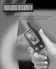
Model Deluxe 62I - Bulldog Security
Model Deluxe 62I - Bulldog Security
Model Deluxe 62I - Bulldog Security
Create successful ePaper yourself
Turn your PDF publications into a flip-book with our unique Google optimized e-Paper software.
<strong>Deluxe</strong> <strong>62I</strong><br />
<strong>Deluxe</strong> Remote Starter<br />
with Alarm and Keyless Entry<br />
<strong>Bulldog</strong> <strong>Security</strong><br />
www.bulldogsecurity.com<br />
225 Technology Way • Steubenville, OH 43952<br />
800-878-8007<br />
INSTALLATION AND OWNER’S GUIDE<br />
©2003 JBS Technologies, LLC ©2003 JBS Technologies, LLC
YOUR WARRANTY<br />
About JBS Technologies<br />
In 1992 JBS Technologies opened its doors as an American owned<br />
and operated automotive security manufacturer. Today, more than<br />
a decade later, we still manufacture in America using the latest<br />
technology and robotic machinery. All units are built with the highest<br />
integrity in our Steubenville, Ohio facility. We at JBS Technologies<br />
pride ourselves on quality and customer service. Thank you for<br />
purchasing an American made product.<br />
Here's how your warranty works:<br />
JBS Technologies warrants to the original customer, in the originally installed vehicle a limited lifetime warranty, providing<br />
the system was installed by an authorized dealer.<br />
Within 12 months of purchase, JBS Technologies will repair or replace, our option, any defective system at no charge. After<br />
12 months from date of purchase, JBS Technologies will, at our option, repair or replace the system for a $20 shipping and<br />
handling fee.<br />
Installation, labor, removal and reinstallation are not the responsibility of JBS Technologies. Registration must be completed<br />
and sent in within ten (10) days of purchase in order to validate the warranty. JBS Technologies makes no warranty against<br />
the theft of a vehicle or its contents. This warranty is not to be construed as an insurance policy against loss.<br />
Incidental, consequential an/or indirect damages are expressly disclaimed. No person or entity is authorized to alter, amend<br />
or increase this limited warranty. All parts and accessories are covered under the expressed warranty with the exception<br />
of the remote transmitter battery.<br />
The Dealer and/or consumer will be responsible for freight or shipping charges to JBS Technologies on all merchandise<br />
returned for repair or replacement. JBS Technologies will be responsible for any freight or shipping charges on product<br />
returned or exchanged back to the Dealer and or consumer.<br />
DISCLAIMER<br />
JBS Technologies disclaims the warranty of merchantability and fitness for any particular use. This disclaimer shall be effective<br />
as to all claims of any kind made by or through any wholesaler, retailer, consumer or any other person or entity. Some states<br />
do not permit the disclaimer of implied warranties in some sales. Hence, this disclaimer may not apply to you.<br />
LIMITATION OF REMEDIES<br />
Consumer's remedy is limited to repair or replacement of the unit, and in no event shall exceed the purchase price. Incidental,<br />
consequential an/or indirect damages are expressly disclaimed. No person or entity is authorized to alter, amend or increase<br />
this limited warranty.<br />
WARRANTY REGISTRATION<br />
FCC/ID J3S0045CHOO - This device complies with Part 15 of FCC rules and regulations.<br />
Operation of this unit is subject to the following two conditions. (1) This device may not cause<br />
harmful interference. (2) This device must accept any interference received, including interference<br />
that may cause undesired operation.<br />
Changes or modifications not expressly approved by the party responsible for the compliance<br />
could void the user’s authority to operate the device.<br />
Your Name ___________________________________________________________<br />
Address ______________________________________________________________<br />
City _________________________________ State ______ Zip Code ___________<br />
Email Address _________________________________________________________<br />
Dealer Name __________________________________________________________<br />
Address ______________________________________________________________<br />
City _________________________________ State ______ Zip Code ___________<br />
Date of Purchase _____________________ <strong>Model</strong>: <strong>Deluxe</strong> <strong>62I</strong><br />
Make/<strong>Model</strong> of Vehicle _______________________________________ Year ______<br />
Final Quality Check By __________________________________________________<br />
Mail this card to: JBS Technologies, 225 Technology Way, Steubenville, OH 43952<br />
V1003<br />
©2003 JBS Technologies, LLC ©2003 JBS Technologies, LLC
OPERATING INSTRUCTIONS<br />
CONTENTS<br />
Adjusting Shock Sensor (Vehicle must be disarmed with engine off)<br />
The on-board shock sensor can be programmed for sensitivity by holding down Button<br />
#4 (Stop) for 5 seconds until a chirp or horn honk is heard. Release Button #4. Tap the<br />
vehicle, directly over the alarm, at the sensitivity level you wish. The harder you hit the<br />
vehicle, the less sensitive the alarm will be. As soon as you impact the vehicle the horn<br />
will honk or the siren will chirp indicating that the sensitivity has been set. If you do not<br />
tap the vehicle the sensitivity will automatically set at maximum. The shock programming<br />
window is 5 seconds.<br />
Minor Violation<br />
The first time that the shock sensor is violated, the parking lights will flash three (3) times<br />
and the horn/siren will chirp three (3) times. If the sensor is violated again within 30<br />
seconds, the unit will go into full violation.<br />
Zone Lockout<br />
if any one zone is violated three (3) times consecutively, that zone will not produce another<br />
violation for the remainder of the arm cycle.<br />
Temporary Silent Arm/Disarm (This Arming Only)<br />
Press and hold Button #2 for approximately two (2) seconds, the parking lights will flash<br />
once, the unit is now programmed for Silent Arming. Release Button #2 and press again,<br />
the parking lights will flash twice, and remain on for one (1) minute, the unit is now<br />
Disarmed.<br />
* When this option has been installed.<br />
KEEP THIS CARD IN YOUR WALLET<br />
(1) (2)<br />
Remote Starting: Press and release Button #1. The parking lights<br />
will flash once confirming the signal was received and the vehicle<br />
will start. Once running, the parking lights will turn on and<br />
(3)<br />
(4)<br />
remain on. If start fails, the unit will make two additional attempts.<br />
Arm/Disarm: Press and release Button #2. The parking lights will<br />
flash once with one chirp from the siren for Arm and the doors will lock.<br />
The parking lights will flash twice with two chirps from the siren for<br />
Disarm and the doors will unlock.<br />
Pit Stop: Exiting the vehicle with the engine running. Make sure the vehicle is in park. Press<br />
Button #1 and then turn the ignition to the off position. The vehicle will remain running.<br />
Valet Mode - On: Press and hold the brake, turn Ignition Key to the Run position. Within<br />
five (5) seconds, press and release Button #4. The horn will sound or the siren will chirp<br />
once, the parking lights flash once and the LED will flash once. Valet is now on. Release the<br />
brake, turn the ignition key off. The LED will remain lit in valet mode. Valet Mode - Off:<br />
Repeat process for Valet Mode On. The horn will sound or the siren will chirp twice, the<br />
parking lights flash twice and the LED will flash twice. Valet is now off. Release the brake,<br />
turn the ignition key off. The LED will now turn off.<br />
Trunk Release: Press and release Button #3, the parking lights will flash and the trunk will<br />
open (if installed).<br />
DELUXE <strong>62I</strong><br />
<strong>Deluxe</strong> Remote Starter with Alarm and Keyless Entry<br />
System Features ............................................................................ 3-5<br />
System Components.......................................................................... 5<br />
Technical Assistance.......................................................................... 6<br />
Before You Begin............................................................................... 6<br />
Precautions....................................................................................... 7<br />
Neutral Safety Switch ........................................................................ 8<br />
Antenna Placement............................................................................ 9<br />
Installation Diagram ........................................................................ 10<br />
Connecting The 18-Pin Harness ................................................... 11-13<br />
Connecting the Main power, Ignition and Accessory Wires...................13<br />
Making Main Power, Ignition and Accessory Connections.....................14<br />
Testing Door Locks ..................................................................... 15-16<br />
Connecting Door Locks................................................................ 17-19<br />
Programming Instructions ........................................................... 20-23<br />
Operating Instructions ................................................................ 24-26<br />
Warranty Registration ...................................................................... 27<br />
SYSTEM FEATURES<br />
<strong>Security</strong> System Features<br />
2 Four-Button Extended Remotely start your car to run the heater or air conditioning from<br />
Range Remote Transmitters an extended distance.<br />
Remote Programmable On- Provides warn away and impact protection.<br />
board Dual Stage Shock Sensor<br />
Remote Programmable<br />
Sensitivity Reduction<br />
Active Arming<br />
Allows you to adjust the shock sensor sensitivity with the remote<br />
transmitter.<br />
This feature will only arm the alarm system with your remote<br />
transmitter.<br />
26<br />
©2003 JBS Technologies, LLC ©2003 JBS Technologies, LLC<br />
3
SYSTEM FEATURES<br />
OPERATING INSTRUCTIONS<br />
<strong>Security</strong> System Features<br />
Starter Immobilizer<br />
Prevents the vehicle from being hotwired when the system is<br />
with Relay<br />
armed.<br />
Remote Car Finder<br />
Remote Valet<br />
Silent Arming<br />
Door Trigger Protection<br />
Horn and Siren Outputs<br />
Helps you locate your vehicle in a crowded parking lot.<br />
Remotely turn off the alarm section when not needed.<br />
Remotely program the alarm to silently arm and disarm with the<br />
remote transmitter.<br />
Provides protection when doors are opened.<br />
Gives you the option to connect a siren or horn, or both, to the<br />
alarm for additional audible protection.<br />
Remote Starter Features<br />
Remote Programmable Remotely program your car to start at a preset temperature.<br />
Automatic Hot and Cold Select desired temperature from 150ºF to -40ºF.<br />
Start<br />
Remote Programmable<br />
Automatic Start<br />
Remote Programmable<br />
Low Voltage Start<br />
Remote Programmable<br />
Run Time<br />
Remote Programmable<br />
Extended Crank Time<br />
Dedicated Start and Stop<br />
Buttons<br />
Diesel Start Capability<br />
Remotely program your car to start every 3 hours regardless of the<br />
temperature.<br />
Remotely program your vehicle to automatically start when the<br />
battery voltage drops below 11 volts.<br />
Remotely program your vehicle to run from 5 to 25 minutes.<br />
Remotely program a longer engine cranking for hard starting<br />
vehicles.<br />
Uses separate buttons to start and stop the remote starter.<br />
Allows you to program the unit to remote start a diesel vehicle.<br />
Trunk Release Output<br />
The remote car starter includes an optional output that can be used to do one of the<br />
following: open the trunk, roll up the windows (optional module required), close the sun<br />
roof (optional module needed) etc. This output will pulse .75 seconds when pressed and<br />
released. In instances where a continuous signal is needed such as sun roof and power<br />
windows, hold down Button #3 (Trunk) as long as the signal is needed to complete the<br />
task. The parking lights will remain on as long as this button is being pressed.<br />
Remote Car Finder (Armed Only)<br />
When the unit is armed, press and release Button #4, the horn or siren will chirp three<br />
(3) times and the parking lights will flash three (3) times.<br />
Runtime Confirmation (Disarmed Only)<br />
With the engine off, press and release Button #4 (Stop). The parking lights will begin to<br />
flash, each flash represents five minutes of programmed runtime. Example: 5 flashes =<br />
25 minutes.<br />
Zone Violation Status<br />
If the unit was violated, there will be three (3) flashes and chirps upon disarming. After<br />
disarming, if the unit was violated, the LED will flash the appropriate number of times to<br />
signify the violated zone. If more than 1 zone was violated, the highest priority zone is<br />
signified. The LED will continually flash the appropriate zone violation for 1 minute or when<br />
the ignition and brake are activated, whichever occurs first. Order of significance is doorpin,<br />
hoodpin, then shock sensor. Shock violation, 2 LED flashes; hoodpin violation, 3 LED flashes;<br />
doorpin violation, 5 LED flashes.<br />
ADDITIONAL OPERATING PROCEDURES:<br />
Valet Mode On<br />
Press and hold the brake, turn Ignition Key to the Run position. Within five (5) seconds,<br />
press and release Button #4. The horn will sound or the siren will chirp once, the parking<br />
lights flash once and the LED will flash once. Valet is now on. Release the brake, turn the<br />
ignition key off. The LED will remain lit in valet mode.<br />
Valet Mode Off<br />
Press and hold the brake, turn Ignition Key to the Run position. Within five (5) seconds,<br />
press and release Button #4. The horn will sound or the siren will chirp twice, the parking<br />
lights flash twice and the LED will flash twice. Valet is now off. Release the brake, turn the<br />
ignition key off. The LED will now turn off.<br />
4<br />
©2003 JBS Technologies, LLC ©2003 JBS Technologies, LLC<br />
25
OPERATING INSTRUCTIONS<br />
SYSTEM FEATURES<br />
(1)<br />
(3)<br />
(2)<br />
(4)<br />
Button #1: Remote starts your vehicle from up to a quarter<br />
mile.<br />
Button #2: Arm locks and disarm unlocks your power door<br />
locks.<br />
Button #3: Pops your trunk.<br />
Button #4: Turns off your remote starter and helps you<br />
locate your car (when system is armed).<br />
Keyless Entry Features<br />
Remote Keyless Entry*<br />
Remote Programmable<br />
Ignition Controlled<br />
Door Locks*<br />
Trunk Release*<br />
Remotely locks and unlocks your power door locks with built-in<br />
relays onboard.<br />
A programmable feature that locks and unlocks the doors when the<br />
brake is depressed and the ignition is on.<br />
Remotely opens your trunk with a push of a button.<br />
Arming/Disarming the <strong>Security</strong> plus Keyless Entry<br />
Press Button #2 (Arm/Disarm), the parking lights will flash once, the horn/siren will sound<br />
once (if connected) and the doors will lock. Press Button #2 again, the parking lights will<br />
flash twice, the horn/siren will sound twice (if connected), the doors will unlock, and the<br />
parking lights will remain on for one minute or until you turn the ignition on and press<br />
the brake.<br />
Disarming the <strong>Security</strong> System without a Remote Transmitter<br />
Open the driver’s door. The door pin input wire must be hooked up. Then press the brake<br />
and cycle the ignition key from “off” to “run” five times. Your alarm system is now disabled.<br />
Starting the Vehicle with the Remote Transmitter<br />
Press and release Button #1 (Start). The parking lights will flash once, confirming the car<br />
starter received the signal. The car will then start and the parking lights will turn on and<br />
remain on while the vehicle is running. To shut off the engine before the preset time,<br />
press Button #4 (Stop), press the brake pedal or open the hood. NOTE: If your car does<br />
not start on the first crank it will automatically attempt to start up to 3 more times (only<br />
in Tachless Mode). In Tachless Mode, parking lights will wait approximately 10 seconds<br />
before turning on.<br />
Pit Stop: Exiting the Car while Leaving the Engine Running<br />
Make sure the transmission is in park and press Button #1 (Start) before turning the<br />
ignition switch off. (The engine will remain running for the preset runtime.)<br />
Dome Light Supervision Option<br />
This system includes an optional output that can be used to illuminate the dome light<br />
when pressing Button #2 and disarming your system. The dome light will remain on for<br />
one minute or until you turn the ignition on and press the brake.<br />
Dome Light Supervision*<br />
Parking Light<br />
Confirmation<br />
Multi-Remote Learning<br />
Limited Lifetime Warranty<br />
* Optional feature.<br />
Never walk up to a dark vehicle again. When unlocking the vehicle<br />
by remote control the dome light will stay on for one minute, or until<br />
you activate the ignition switch.<br />
Confirms that your vehicle has received a remote signal and will<br />
remain on if the engine is remotely started.<br />
Allows your remote starter to learn new remotes, should you want<br />
to add remotes, or if remotes are lost.<br />
Guarantees life-long protection.<br />
COMPONENTS<br />
This system includes:<br />
1-Installation and Owner’s Guide<br />
1-RXM Extended Range Antenna with<br />
1-Main Control Module Superbright L.E.D.<br />
2-Four Button Remote Transmitters<br />
1-4-Pin Antenna Harness<br />
1-18-Pin Wire Harness<br />
1-Warning Sticker for Under the Hood<br />
1-5-Pin Harness (door locks)<br />
2-Window Decals<br />
6-Heavy Gauge Wires w/ Spade Connectors 1-Warranty<br />
1-Hood Switch<br />
24<br />
©2003 JBS Technologies, LLC ©2003 JBS Technologies, LLC<br />
5
TECHNICAL ASSISTANCE<br />
PROGRAMMING INSTRUCTIONS<br />
Should you need help. First check our website at www.bulldogsecurity.com/<br />
wires.htm or call our toll-free Tech Support Hotline at 800-878-8007 Monday<br />
through Friday 9AM-8PM and Saturday 10AM-4PM EST.<br />
BEFORE YOU BEGIN<br />
You have chosen one of the most advanced remote starter systems ever<br />
made. This system is a technological breakthrough utilizing the most advanced,<br />
state-of-the-art technology and components. It is computer controlled and<br />
manufactured in the U.S.A. The dependability and variety of features make<br />
<strong>Bulldog</strong> <strong>Security</strong> the leader in the industry.<br />
This system is designed to start the vehicle by sending a command signal<br />
from the remote transmitter or by programming automatic temperature or<br />
timed start. It is required that installation be done in a well-ventilated area.<br />
It is the responsibility of the owner to ensure that the system is not<br />
used to start the vehicle in an undesired location. It is recommended<br />
that a carbon monoxide detector be installed in the living area near where<br />
the vehicle will be garaged.<br />
This system requires no regular maintenance. Your remote transmitter is<br />
powered by a small 12-volt A23 battery. Its approximate life is one to two<br />
years under normal use. Indications that the battery has begun to weaken<br />
are reduced range and/or dimming of the LED on the remote transmitter.<br />
Valet Mode Off<br />
Press and hold the brake, turn Ignition Key to the Run position. Within five (5) seconds, press<br />
and release Button #4 (Stop). The horn will sound or the siren will chirp twice, the parking lights<br />
twice and the LED will flash twice. Valet is now off. Release the brake, turn the ignition key off.<br />
The LED will now turn off.<br />
Temporary Silent Arm/Disarm (This Arming Only)<br />
Press and hold Button #2 (Arm/Disarm) for approximately two (2) seconds, the parking lights<br />
will flash once, the unit is now programmed for Silent Arming. Press and release Button #2, the<br />
parking lights will flash twice, and remain on for one (1) minute, the unit is now Disarmed.<br />
Silent Arm/Disarm<br />
(Remains In Silent Mode Until Programmed Back On)<br />
Press and hold Button #2 for approximately five (5) seconds, when arming, the parking lights<br />
will flash without the horn or siren sounding. Hold until the parking lights flash three (3) times,<br />
release. Silent arming/disarming is now programmed on. To program it back on, repeat these<br />
steps. After the parking lights flash again three (3) times, silent arming/disarming is programmed<br />
off.<br />
Disarming the <strong>Security</strong> System without a Remote<br />
Open the hood. (The hood switch must be hooked up or the BLACK WITH BLUE STRIPE wire<br />
needs to be grounded.) Press the foot brake and cycle the ignition key from “off” to “run” five<br />
times. Your alarm system is now disarmed.<br />
Runtime Programming (Engine Off)<br />
Press and hold Button #4 (stop) for approximately 10 seconds. The horn will honk twice, then<br />
the parking lights will begin to flash, each flash represents 5 minutes with the maximum being<br />
25 minutes, 5 flashes. Simply release button at whatever runtime you desire. To check programmed<br />
runtime, press and release Button #4 (stop). The parking lights will flash for the amount of<br />
runtime you have programmed the unit for.<br />
Clearing the Memory of the Unit<br />
Press and hold the brake pedal, now cycle the key in the ignition switch from OFF to RUN (not<br />
start) five (5) times within four (4) seconds. Release the brake, now try the remote. The unit<br />
should not function with the remote. If the unit does not function, unplug the unit from both<br />
harnesses, wait one (1) minute and plug it back in. Press Button #4 (stop) the parking lights<br />
will flash three (3) times, the unit is now back to factory default and ready to operate.<br />
6 23<br />
©2003 JBS Technologies, LLC ©2003 JBS Technologies, LLC
PROGRAMMING INSTRUCTIONS<br />
PRECAUTIONS<br />
Programming Hot Start<br />
Press and hold the brake, then press and hold Button #2 (Arm/Disarm) until the parking lights<br />
flash twice. Release Button #2. Press and hold Button #3, the parking lights will flash once.<br />
Each continuous flash represents a progression in degrees: one (1) flash = 150ºF, two (2)<br />
flashes = 140ºF, three (3) flashes = 130ºF, four (4) flashes = 120ºF, five (5) flashes = 110ºF,<br />
six (6) flashes 100ºF. To disable Hot Start, press and hold Button #3 until the parking lights<br />
flash six (6) times, then two (2) quick flashes for 7 and 8. The Hot Start is now disabled. Release<br />
the brake, the parking lights will flash three (3) times, the programming is now entered. NOTE:<br />
The factory setting is Hot Start off. NOTE: Only Cold and Hot Start functions can be enabled<br />
at the same time. If button #1 is pressed for programming, Cold/Hot Start is disabled. When<br />
Buttons #2 and #3 are pressed, then the Automatic and Low Voltage Starts are disabled.<br />
Programming Tach/Tachless Start<br />
Press and hold the brake, then press and hold Button #3 (Trunk) until the parking lights flash<br />
three (3) times. Release Button #3. Press and release Button #4, the parking lights will flash<br />
once. The unit is now in Tach Start Mode. Press and release Button #4, the parking lights will<br />
flash twice. The unit is now in Tachless Start Mode. Release the brake, the parking lights will<br />
flash three (3) times. The programming is now entered. NOTE: Factory setting is Tachless Start<br />
Mode.<br />
Programming Diesel Start<br />
Press and hold the brake, then press and hold Button #4 (Stop) until the parking lights flash<br />
four (4) times. Release Button #4. Press and release Button #1, the parking lights will flash<br />
once. The unit is now programmed for Diesel Start Mode. Press and release Button #1, the<br />
parking lights will flash twice, Diesel Start Mode is now off. Release the brake, the parking lights<br />
will flash three (3) times. The programming is now entered. NOTE: Factory setting is Diesel<br />
Start off. When programming Diesel Start, the unit will automatically program for Tach Start.<br />
Programming Glow Plug Timer<br />
Press and hold the brake, then press and hold Button #4 (Stop) until the parking lights flash<br />
four (4) times. Release Button #4 and press again.<br />
One (1) parking light flash = 5 second start delay.<br />
Two (2) parking light flashes = 10 second start delay.<br />
Three (3) parking light flashes = 15 second start delay.<br />
Four (4) parking light flashes =Timer off. (must use sense wire)<br />
NOTE: You must first program Diesel Start On.<br />
SPECIAL PROGRAMMING MODE:<br />
Valet Mode On<br />
Press and hold the brake, turn Ignition Key to the Run position. Within five (5) seconds, press<br />
and release Button #4 (Stop). The horn will sound or the siren will chirp once, the parking<br />
lights once and the LED will flash once. Valet is now on. Release the brake, turn the ignition<br />
key off. The LED will remain lit in valet mode.<br />
This system is designed to be used with fuel-injected and diesel<br />
vehicles with automatic transmissions only.<br />
SAFETY FIRST!<br />
Never remote start the vehicle if it is indoors or if the keys are in the ignition.<br />
Always be sure that the vehicle is in park.<br />
DO NOT use mechanical wiring connections, such as crimp or snap together<br />
taps.<br />
DO NOT disconnect the battery if the vehicle has an anti-theft-coded radio<br />
or is equipped with an airbag. Doing so may cause a warning light to be<br />
displayed.<br />
DO NOT leave the interior or exterior lights on for an extended period of time<br />
as it may cause battery drain. Remove the dome light fuse from the vehicle’s<br />
fuse box. NOTE: Starter systems do not work well with a partially discharged<br />
battery.<br />
DO NOT mount the control module until all connections have been made and<br />
tested. Using wire ties or double sided tape, MOUNT THE MODULE UNDER<br />
THE DRIVER’S DASH. Place the warning sticker under the hood.<br />
PLEASE USE CAUTION: DO NOT CUT, PROBE OR DISCONNECT THE<br />
VEHICLE’S AIRBAG WIRES. THESE WIRES WILL ALMOST ALWAYS<br />
BE INSIDE A BRIGHT YELLOW TUBE LOCATED NEAR THE<br />
STEERING COLUMN HARNESS.<br />
WARNING! – GENERAL MOTORS REAR WHEEL DRIVE VEHICLES AND<br />
DODGE DAKOTAS All General Motors rear wheel drive vehicles and Dodge<br />
Dakotas built prior to 1996 do not have an electrical Neutral Safety switch.<br />
They have a mechanical neutral safety switch. The mechanical neutral safety<br />
switch operates as follows.<br />
a) The key will only turn to start position when the gear selector is in park<br />
or neutral.<br />
b) The key can only be removed from the ignition switch when the gear<br />
selector is in the park position.<br />
You must use special precautions with this system. (See Neutral Safety Switch,<br />
page 8.)<br />
22 7<br />
©2003 JBS Technologies, LLC ©2003 JBS Technologies, LLC
NEUTRAL SAFETY SWITCH<br />
PROGRAMMING INSTRUCTIONS<br />
MECHANICAL NEUTRAL SAFETY SWITCH (Rear Wheel Drive Only)<br />
When installing a <strong>Bulldog</strong> <strong>Security</strong> remote starter on GM vehicles or Dodge<br />
Dakotas built prior to 1996, you must: Use the diagram below to create<br />
a circuit that will prevent the remote starter from starting the vehicle<br />
unless the key is removed from the ignition switch.<br />
PRE-1996 GM REAR WHEEL DRIVES<br />
WITH PURPLE CRANK WIRE – Optional relay required.<br />
Key<br />
Cylinder<br />
PRE-1996 DODGE DAKOTAS – Optional relay required.<br />
Key<br />
Cylinder<br />
BLACK/<br />
LT.BLUE<br />
Driver’s Door Switch<br />
TAN<br />
Ground<br />
GREEN<br />
Message center<br />
or key buzzer<br />
Driver’s Door Switch<br />
Ground<br />
LT.BLUE/<br />
GREEN<br />
Message center or<br />
key buzzer<br />
Ignition<br />
5 Amp<br />
fuse<br />
(-) Negative<br />
hood pin wire<br />
Ignition<br />
5 Amp<br />
fuse<br />
(-) Negative<br />
hood pin wire<br />
86<br />
86<br />
87<br />
87a<br />
87<br />
87a<br />
30<br />
30<br />
85<br />
85<br />
Ground<br />
NOT USED,<br />
TAPE OFF<br />
Ground<br />
NOT USED,<br />
TAPE OFF<br />
Programming Shock Sensor On and Off (See Adjusting Shock Sensor)<br />
Press and hold the brake, then press and hold Button #4 (stop) until the parking lights flash<br />
four (4) times. Release Button #4. Press and release Button #2, the parking lights will flash<br />
once the shock sensor is now ON. Press and release Button #2, the parking lights will flash twice<br />
the shock sensor is now OFF. Release the brake, the parking lights will flash three (3) times.<br />
The programming is now entered. NOTE: Factory setting is Shock Sensor on.<br />
Programming Tach Learn<br />
Press and hold the brake, then press and hold Button #2 until the parking lights flash twice.<br />
Release Button #2. NOTE: The unit must be set to Tach Start first. Next, turn the ignition on.<br />
(If your vehicle is a diesel, wait for the glow plug to go out then proceed to the next step) Start<br />
the engine with the key then press and release Button #4. The parking lights will flash once.<br />
When the parking lights flash two more times, the tach signal has been learned.<br />
Adjusting Shock Sensor (Disarmed Engine Off)<br />
The on-board shock sensor can be programmed for sensitivity by holding down Button #4 (Stop)<br />
for 5 seconds until a chirp or horn honk is heard. Release Button #4. Tap the vehicle, directly<br />
over the alarm, at the sensitivity level you wish. The harder you hit the vehicle, the less sensitive<br />
the alarm will be. As soon as you impact the vehicle the horn will honk or the siren will chirp<br />
indicating that the sensitivity has been set. If you do not tap the vehicle the sensitivity will<br />
automatically set at maximum. The shock programming window is 5 seconds.<br />
Programming Automatic Start Options<br />
Press and hold the brake, then press and hold Button #2 (Arm/Disarm) until the parking lights<br />
flash twice. Release Button #2. Press and release Button #1, the parking lights will flash once.<br />
You are now in 3 hour Start Mode. Your vehicle will start every three (3) hours. Press and<br />
release Button #1 a second time. The parking lights will flash twice for Low Voltage Start. To<br />
discontinue automatic start options, press and release Button #1 a third time. The parking lights<br />
will flash three (3) times, the Automatic Start Option is now off. Release the brake, the<br />
parking lights will flash three (3) times. The programming is now entered. NOTE: The factory<br />
setting is Automatic Start Option off.<br />
Programming Cold Start<br />
Press and hold the brake, then press and hold Button #2 (Arm/Disarm) until the parking lights<br />
flash twice. Release Button #2. Press and hold Button #2, the parking lights will flash once.<br />
Each continuous flash represents a progression in degrees: one (1) flash = -40ºF, two (2) flashes<br />
= -30ºF, three (3) flashes = -20ºF, four (4) flashes = -10ºF, five (5) flashes = 0ºF, six (6) flashes<br />
= 10ºF, seven (7) flashes = 20ºF. To disable Cold Start, press and hold Button #2 until the<br />
parking lights flash seven (7) times, then two (2) quick flashes 8 and 9. The Cold Start is now<br />
disabled. Release the brake, the parking lights will flash three (3) times, the programming is<br />
now entered. NOTE: The factory setting is Cold Start off.<br />
8<br />
21<br />
©2003 JBS Technologies, LLC ©2003 JBS Technologies, LLC
PROGRAMMING INSTRUCTIONS<br />
ANTENNA PLACEMENT<br />
WE RECOMMEND THAT YOU USE FACTORY SETTINGS FIRST<br />
Entering Programming Mode<br />
Make sure your key is not in the ignition and the brake is pressed. The brake is to remain<br />
pressed as long as you want to remain in programming mode. The unit will exit the programming<br />
mode simply by releasing the brake. The parking lights will flash three (3) times confirming<br />
that you are out of programming mode.<br />
Antenna Wire<br />
Antenna<br />
Programming Double Crank Time<br />
Press and hold the brake, press and hold Button #3 (Trunk) until the parking lights flash three<br />
(3) times. Release Button #3. Press and release Button #3, the parking lights will flash once.<br />
The Double Crank is on. Press and release Button #3, the parking lights will flash twice, Double<br />
Crank is now off. Release the brake, the parking lights will flash three (3) times, the programming<br />
is now entered. NOTE: Factory setting is Double Crank off.<br />
Adding New Transmitters<br />
Press and hold the brake, then press and hold Button #1 (Start) on the working remote until<br />
the parking lights flash once. Release Button #1. Press any button on the new remote, the<br />
parking lights will flash three (3) times, the new remote is now programmed.<br />
Programming Lock with Brake, Unlock with Ignition Off<br />
Press and hold the brake, then press and hold Button #3 (Trunk) until the parking lights flash<br />
three (3) times. Release Button #3. Press and release Button #2, the parking lights will flash<br />
once. The unit will now lock with the brake and unlock when the ignition is turned off. Press<br />
and release Button #2 again, the parking lights will flash twice. The Lock with Brake feature<br />
is now turned off. Release the brake, the parking lights will flash three (3) times. The programming<br />
is now entered. NOTE: Factory setting is Lock with Brake off.<br />
Programming Door Lock Pulse Length<br />
Press and hold the brake, then press and hold Button #3 (trunk) until the parking lights flash<br />
three (3) times. Release Button #3. Press and release Button #1, the parking lights will flash<br />
once, the door lock pulse length is now 3.5 seconds. Press and release Button #1, the parking<br />
lights will flash twice, the door lock pulse length is now .7 seconds. Release the brake, the<br />
parking lights will flash three (3) times. The programming is now entered. NOTE: Factory Door<br />
Lock Pulse Setting is .7 seconds.<br />
Programming Double Pulse Unlock<br />
Press and hold the brake, then press and hold Button #4 (stop) until the parking lights flash<br />
four (4) times. Release Button #4. Press and release Button #3, the parking lights will flash<br />
once. Double Pulse Unlock is on. Press and release Button #3 a second time, the parking lights<br />
will flash twice. Double Pulse Unlock is off and Double Pulse Lock is on. Press and release Button<br />
#3 a third time, the parking lights will flash three times. Double Pulse Lock and Double Pulse<br />
Unlock are on. Press and release Button #3 a fourth time, the parking lights will flash four<br />
times. Double Pulse Lock and Double Pulse Unlock are now programmed off. NOTE: Factory<br />
Setting is Double Pulse Unlock off.<br />
Control Module<br />
Run the antenna 4-pin harness up the windshield pillar on the driver’s side<br />
and across the top of the windshield tucking the antenna harness inside the<br />
headliner, behind the rearview mirror. NOTE: Before mounting the antenna<br />
to the windshield, first clean the glass with an alcohol pad. Plug the<br />
RED 4-pin harness from the antenna into the RED connector on the back of<br />
the unit. It will perform best if mounted below the dark windshield tint. Each<br />
receiver is tested to more than 1/4 mile of clear air reception. While many<br />
times you will see 1/2 mile or more. Many factors will affect the range,<br />
including the amount of radio signals in the area, battery strength, window<br />
tint, etc.<br />
NOTE: There is a red or blue LED light in the window mounted antenna<br />
receiver that will blink when locking or arming the keyless entry with the<br />
remote transmitter.<br />
The LED light is designed as a theft deterrent and is recommended by<br />
automotive insurance companies.<br />
20 9<br />
©2003 JBS Technologies, LLC ©2003 JBS Technologies, LLC
INSTALLATION DIAGRAM<br />
CONNECTING DOORLOCKS<br />
WHEN ADDING<br />
DOORLOCK ACTUATORS<br />
5-PIN DOORLOCK HARNESS<br />
1 2 3 4 5<br />
RED 12 V CONSTANT<br />
WHITE/BLACK ACCESSORY<br />
RED 12 V CONSTANT<br />
YELLOW/BLACK STARTER CRANK<br />
4-PIN<br />
ANTENNA HARNESS<br />
ANTENNA<br />
PLUG<br />
12V(+)<br />
12V(+)<br />
WHITE/<br />
BLACK<br />
YELLOW/<br />
BLACK<br />
18-PIN HARNESS<br />
1-800-878-8007<br />
www.bulldogsecurity.com<br />
Tested To Comply<br />
With FCC Standards<br />
F C<br />
<strong>Bulldog</strong> <strong>Security</strong> M200<br />
UP<br />
DOWN<br />
IGN IGN<br />
1 2<br />
DOORLOCK<br />
5-PIN<br />
HARNESS<br />
DOOR #1<br />
CENTRAL LOCKING<br />
SYSTEM<br />
BLUE/BLACK<br />
BLUE/WHITE<br />
RED/BLACK<br />
GREEN/BLACK<br />
GREEN/WHITE<br />
WHITE/RED IGNITION #2<br />
WHITE IGNITION #1<br />
DOORLOCK ACTUATOR<br />
CUT IN HALF<br />
87a<br />
KEYSIDE OF<br />
STARTER WIRE<br />
1.BROWN (+) OR (-)<br />
PARKING LIGHT OUTPUT<br />
(Programmable)<br />
2.ORANGE (-)<br />
STARTER KILL OUTPUT<br />
3.WHITE/RED (+) OR (-)<br />
TRUNK RELEASE OUTPUT<br />
(Programmable)<br />
4.VIOLET (+) OR (-)<br />
DOME LIGHT SUPERVISION<br />
OUTPUT (Programmable)<br />
5.BLUE (-) AMA INPUT<br />
18.GREY (+)<br />
SIREN OUTPUT<br />
17.GREY/BLACK (-)<br />
HORN OUTPUT<br />
16.YELLOW (-)<br />
SECURITY BYPASS OUTPUT<br />
15.BLUE/BLACK (+)<br />
BRAKE INPUT<br />
14.BLACK/YELLOW (+)<br />
DOOR PIN INPUT<br />
BLUE<br />
(NOT USED)<br />
HORN WIRE<br />
BLACK GROUND<br />
RED<br />
OR DOOR #2<br />
Without<br />
factory power<br />
door locks.<br />
TO 12 V (+)<br />
CONSTANT<br />
GROUND<br />
NOTE: This is the correct<br />
order of wire colors in<br />
the 5-pin harness.<br />
6.BLACK/BLUE (-)<br />
HOOD PIN INPUT<br />
13.GREEN (-)<br />
DOOR PIN INPUT<br />
12V (+) GROUND<br />
7.BLACK/WHITE (-)<br />
TACH INPUT<br />
12V (+)<br />
8.GREEN/BLACK (+)<br />
DIESEL GLOW PLUG INPUT<br />
12.RED/BLACK (-)<br />
FACTORY ALARM OUTPUT<br />
GROUND<br />
12V (+)<br />
DOORLOCK ACTUATOR<br />
GROUND<br />
GLOW PLUG OR<br />
WAIT TO START<br />
WIRE<br />
9.BROWN/BLACK (-)<br />
DIESEL GLOW<br />
PLUG INPUT<br />
10. NOT USED<br />
11.BLACK<br />
GROUND<br />
10<br />
19<br />
©2003 JBS Technologies, LLC ©2003 JBS Technologies, LLC
CONNECTING DOORLOCKS<br />
CONNECTING THE 18-PIN HARNESS<br />
5-PIN HARNESS<br />
4<br />
5<br />
3<br />
1<br />
2<br />
“Type C” Reverse Polarity<br />
(5-pin harness)<br />
GREEN/BLACK Unlock Out<br />
GREEN/WHITE Unlock In<br />
RED/BLACK<br />
BLUE/BLACK Lock Out<br />
BLUE/WHITE Lock In<br />
+12V Constant<br />
NOTE: Connect the RED WITH BLACK STRIPE<br />
wire to +12V constant power.<br />
POWER<br />
DOOR<br />
LOCK<br />
MOTOR<br />
LOCK<br />
MODULE LAYOUT<br />
ANTENNA<br />
18-PIN HARNESS<br />
9 8 7 6 5 4 3 2 1<br />
18 17 16 15 14 13 12 11 10<br />
PARKING LIGHT TRUNK DOME LIGHT<br />
DOOR LOCK HARNESS<br />
IGN 1 IGN 2<br />
IN (+)<br />
OUT (-)<br />
CAUTION: Please check the position of the switch before the wire connection is made. You<br />
may cause damage to the control module if the incorrect switch polarity is chosen.<br />
CAUTION: The negative output for the trunk release and parking light is only 250ma and<br />
is designed for relay or BCM (computer module) connections only.<br />
When not hooking directly to the Body control module a relay must be used to energize<br />
a negative circuit.<br />
The part number for the relay is #775. You can purchase this part online at<br />
www.directwholesale.net or call 800-659-0764.<br />
UNLOCK<br />
One Wire Door Lock System (This is an example only)<br />
5<br />
3<br />
1<br />
2<br />
5-PIN HARNESS4<br />
GREEN/BLACK Lock Out<br />
GREEN/WHITE Not Used<br />
RED/BLACK<br />
BLUE/BLACK Lock Out<br />
620 OHM resistor<br />
to unlock, must<br />
be 5% tolerance.<br />
+12V Constant<br />
2700 OHM resistor<br />
BLUE/WHITE Not Used to lock, must be<br />
5% tolerance.<br />
NOTE: Connect the RED WITH BLACK STRIPE<br />
wire to +12V constant power.<br />
This is an example<br />
only. Resistor values<br />
and 12V or ground<br />
may vary depending<br />
on make and model<br />
of the vehicle.<br />
1. BROWN (+) or (-)<br />
Parking Light Output<br />
Attach to the vehicles parking light wire.<br />
Note: Adjust the switch for positive or<br />
negative output.<br />
2. ORANGE (-) (Opt. part #773 req.)<br />
Starter Immobilizer Output<br />
Provides negative output to starter<br />
immobilizer relay.<br />
3. WHITE/RED (+) or (-)<br />
Trunk Release or Channel #2 Output<br />
Note: Adjust the switch for positive<br />
or negative output.<br />
4. VIOLET (+) or (-)<br />
Dome Light Output<br />
Provides positive or negative output<br />
for domelight supervision.<br />
STARTER IMMOBILIZER OUTPUT<br />
Part #773<br />
ORANGE<br />
FROM 18-PIN<br />
HARNESS<br />
WHITE<br />
STARTER SIDE<br />
Diode<br />
87a<br />
RED<br />
SWITCH SIDE<br />
Note: Adjust the switch for positive or negative output.<br />
5. BLUE (-) AMA (Aftermarket Alarm Activation)<br />
When this wire receives a ground signal, it can start or stop the remote<br />
starter section of the unit.<br />
18 11<br />
©2003 JBS Technologies, LLC ©2003 JBS Technologies, LLC
CONNECTING THE 18-PIN HARNESS<br />
CONNECTING DOORLOCKS<br />
6. BLACK/BLUE (-) Hood Switch Input<br />
This feature will keep the engine from starting or shut off the engine<br />
when the hoop is opened. Locate a good chassis ground with one inch of<br />
clearance for adjustment. Do not install the hood switch in a rain gutter.<br />
Drill a 5/16” hole. Insert the hood switch into the hole, check for the<br />
hood adjustment. The switch will remain neutral when the hood is closed<br />
and will show ground when the hood is open. Connect this wire from the<br />
18-pin harness to the hood switch.<br />
7. BLACK/WHITE (-) Tach (Optional) MUST USE WITH DIESEL ENGINES<br />
Attach to the negative side of the coil or coil pack. Note: You must<br />
program for tach and tach learn when using this wire.<br />
(See Programming Tach/Tachless and Diesel Start, page 22.)<br />
8. GREEN/BLACK (+) Diesel Glow Plug Input (Optional)<br />
This wire is for diesel vehicles with a positive glow plug light wire to<br />
delay the remote starter. You may also program module for time start<br />
delay. (See Programming Glow Plug Timer, page 22.)<br />
9. BROWN/BLACK (-) Diesel Glow Light Input (Optional)<br />
This wire is for vehicles with a negative glow plug light wire to delay<br />
the remote starter. You may also program your module for time delay<br />
start. (See Programming Glow Plug Timer, page 22.)<br />
10. Open Pin (not used)<br />
11. BLACK (-) Frame Ground<br />
Attach to clean chassis ground.<br />
12. RED/BLACK (-) F.A.S.D. (Factory Alarm Shut Down)<br />
This wire provides a negative output to disable the factory security<br />
system.<br />
13. GREEN (-) Door Pin Input<br />
This wire will activate the alarm when it receives a (-) negative signal.<br />
This wire needs to be installed on vehicles that have a negative output<br />
on door pin switches when a door is opened.<br />
14. BLACK/YELLOW (+) Door Pin Input<br />
This wire will activate the alarm when it receives a (+) positive 12 volt<br />
signal. This wire needs to be installed on vehicles that have a positive<br />
output on door pin switches when a door is opened.<br />
15. BLUE/BLACK (+) Brake Pedal Input<br />
When this wire receives 12 volts (+), it will shut down the remote<br />
starter. The correct wire will show 12 volts (+) only when the brake is<br />
pressed.<br />
16. YELLOW (-) Output to <strong>Security</strong> Bypass<br />
This wire will provide a negative output for vehicles that require an<br />
add-on anti-theft bypass system.<br />
5-PIN HARNESS<br />
5-PIN HARNESS<br />
4<br />
5<br />
3<br />
1<br />
2<br />
4<br />
5<br />
3<br />
1<br />
2<br />
“Type A” (+) Positive (5-pin harness)<br />
GREEN/BLACK Unlock Out<br />
GREEN/WHITE Not Used<br />
RED/BLACK<br />
BLUE/BLACK Lock Out<br />
BLUE/WHITE Not Used<br />
NOTE: Connect the RED WITH<br />
BLACK STRIPE wire to +12V constant.<br />
GREEN/BLACK Unlock Out<br />
GREEN/WHITE Not Used<br />
RED/BLACK<br />
BLUE/BLACK Lock Out<br />
BLUE/WHITE Not Used<br />
+12V Constant<br />
“Type B” (-) Negative (5-pin harness)<br />
NOTE: Connect the RED WITH<br />
BLACK STRIPE wire to ground.<br />
Ground<br />
UNLOCK<br />
LOCK<br />
UNLOCK<br />
LOCK<br />
12<br />
17<br />
©2003 JBS Technologies, LLC ©2003 JBS Technologies, LLC
TESTING DOORLOCKS<br />
CONNECTING THE 18-PIN HARNESS<br />
Testing Switch Wire and Motor Wires<br />
for” Type C” Door Locks<br />
Before connecting, you must now determine which wire is the switch wire<br />
and which is the motor wire. Cut both the lock and unlock wires in two. Clip<br />
end of your test light to ground, hold the door lock switch in the lock position,<br />
make sure you are using the master switch (always on the driver’s door)<br />
and probe both lock wires looking for voltage. The wire that illuminates the<br />
test light, mark as the switch wire, the wire that shows no voltage, mark as<br />
the motor wire. Repeat the procedure for the unlock wire.<br />
One Wire Door Lock System<br />
Some vehicles have a single switch wire for both lock and unlock. This system<br />
will wire as a “Type A” or “Type B” depending on the vehicle. The only<br />
difference being this system will require one or two resistors depending on<br />
the make and model of the vehicle. Please consult our website for the proper<br />
resistor value for your vehicle.<br />
17. GREY/BLACK (-) Horn Output<br />
This wire will provide a negative output to the vehicles horn relay.<br />
18. GREY (+) Siren Output<br />
This wire will provide a positive output for an aftermarket siren or<br />
pager.<br />
CONNECTING THE MAIN POWER,<br />
IGNITION AND ACCESSORY WIRES<br />
1. RED (+) Power Input<br />
There are two large gauge RED wires with 25 amp fuse holders that plug<br />
into the top of the control module. These two wires must attach to vehicles<br />
battery feed at the ignition switch harness.<br />
2. WHITE (+) Ignition #1 Output<br />
This wire must attach to the vehicles ignition switch wire that shows 12<br />
volts in the run and crank positions. This wire will plug in next to the<br />
18-pin harnesses.<br />
3. WHITE/RED (+) Ignition #2 Output<br />
This wire is for vehicles that have more than one ignition wire. Plug the<br />
wire next to the 5-pin harnesses.<br />
4. WHITE/BLACK (+) Accessory Output<br />
This wire must attach to the vehicles ignition switch wire that runs the<br />
heater blower circuit. Plug this wire in on top of the control module.<br />
5. YELLOW/BLACK (+) Starter Crank Output<br />
This wire must attach to the vehicles ignition switch wire that shows 12<br />
volts in the start/crank position only. Plug this wire in on top of the control<br />
module.<br />
16 13<br />
©2003 JBS Technologies, LLC ©2003 JBS Technologies, LLC
MAKING MAIN POWER, IGNITION AND ACCESSORY<br />
CONNECTIONS TO THE IGNITION SWITCH HARNESS<br />
TESTING DOORLOCKS<br />
1-800-878-8007<br />
www.bulldogsecurity.com<br />
F C<br />
Tested To Comply<br />
With FCC Standards<br />
WHITE/<br />
BLACK<br />
12V(+)<br />
<strong>Bulldog</strong> <strong>Security</strong> M200<br />
YELLOW/<br />
BLACK<br />
12V(+)<br />
DOORLOCK<br />
IGN IGN<br />
1 2<br />
UP<br />
ANTENNA<br />
PLUG<br />
5-PIN<br />
HARNESS<br />
DOWN<br />
18-PIN<br />
HARNESS<br />
WHITE/RED<br />
IGNITION #2<br />
WHITE<br />
IGNITION #1<br />
WHITE/BLACK<br />
ACCESSORY<br />
YELLOW/BLACK<br />
STARTER/CRANK<br />
RED<br />
CONSTANT 12V<br />
RED<br />
CONSTANT 12V<br />
IGNITION<br />
SWITCH HARNESS<br />
IN VEHICLE<br />
There are four basic types or door locks:<br />
“Type A” Door Lock Test (Most GMs and some Chryslers)<br />
Probe both of your door lock wires going to the door lock switch usually located<br />
in the driver’s kick panel. Attach the clip end of your test light to a good<br />
chassis ground. Using the vehicle’s door lock controls, activate the lock then<br />
the unlock, testing both wires one at a time. If one of these wires tests (+)<br />
positive when lock is pressed and the other tests (+) positive when they are<br />
unlocked, your vehicle has a “Type A” door locking system. NOTE: “Type A”<br />
and “Type C” locks will test the same, until you test for ground. Make sure<br />
you run both tests before making your connections.<br />
“Type B” Door Lock Test<br />
(Most Imports, some newer Fords)<br />
Probe both of your door lock wires going to the door lock switch usually located<br />
in the driver’s kick panel. Attach the clip end of your test light to +12V. Using<br />
the vehicle’s door lock controls, activate the lock then the unlock testing both<br />
wires one at a time. If the test light illuminates when you probe the lock and<br />
the unlock wires your vehicle has a “Type B” door locking system.<br />
“Type C” Door Lock Test<br />
(Most Fords, some Chryslers, GM Trucks)<br />
Using your test light probe both the lock and the unlock wires usually located<br />
in the driver’s kick panel. Attach the clip end of your test light to ground<br />
probing both wires one at a time while locking and unlocking the doors with<br />
the driver’s side switch (usually the master switch). The test light should<br />
illuminate in both switch positions. Now attach the clip end of your test light<br />
to +12V constant, probe both wires one at a time again. The light should then<br />
illuminate again only in reverse order. This tells you that you have a “Type<br />
C” reversing polarity system. Make sure to mark which wire is lock and unlock.<br />
14<br />
15<br />
©2003 JBS Technologies, LLC ©2003 JBS Technologies, LLC


