Model Deluxe 62I - Bulldog Security
Model Deluxe 62I - Bulldog Security
Model Deluxe 62I - Bulldog Security

You also want an ePaper? Increase the reach of your titles
YUMPU automatically turns print PDFs into web optimized ePapers that Google loves.
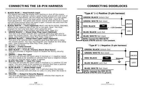
CONNECTING THE 18-PIN HARNESS<br />
CONNECTING DOORLOCKS<br />
6. BLACK/BLUE (-) Hood Switch Input<br />
This feature will keep the engine from starting or shut off the engine<br />
when the hoop is opened. Locate a good chassis ground with one inch of<br />
clearance for adjustment. Do not install the hood switch in a rain gutter.<br />
Drill a 5/16” hole. Insert the hood switch into the hole, check for the<br />
hood adjustment. The switch will remain neutral when the hood is closed<br />
and will show ground when the hood is open. Connect this wire from the<br />
18-pin harness to the hood switch.<br />
7. BLACK/WHITE (-) Tach (Optional) MUST USE WITH DIESEL ENGINES<br />
Attach to the negative side of the coil or coil pack. Note: You must<br />
program for tach and tach learn when using this wire.<br />
(See Programming Tach/Tachless and Diesel Start, page 22.)<br />
8. GREEN/BLACK (+) Diesel Glow Plug Input (Optional)<br />
This wire is for diesel vehicles with a positive glow plug light wire to<br />
delay the remote starter. You may also program module for time start<br />
delay. (See Programming Glow Plug Timer, page 22.)<br />
9. BROWN/BLACK (-) Diesel Glow Light Input (Optional)<br />
This wire is for vehicles with a negative glow plug light wire to delay<br />
the remote starter. You may also program your module for time delay<br />
start. (See Programming Glow Plug Timer, page 22.)<br />
10. Open Pin (not used)<br />
11. BLACK (-) Frame Ground<br />
Attach to clean chassis ground.<br />
12. RED/BLACK (-) F.A.S.D. (Factory Alarm Shut Down)<br />
This wire provides a negative output to disable the factory security<br />
system.<br />
13. GREEN (-) Door Pin Input<br />
This wire will activate the alarm when it receives a (-) negative signal.<br />
This wire needs to be installed on vehicles that have a negative output<br />
on door pin switches when a door is opened.<br />
14. BLACK/YELLOW (+) Door Pin Input<br />
This wire will activate the alarm when it receives a (+) positive 12 volt<br />
signal. This wire needs to be installed on vehicles that have a positive<br />
output on door pin switches when a door is opened.<br />
15. BLUE/BLACK (+) Brake Pedal Input<br />
When this wire receives 12 volts (+), it will shut down the remote<br />
starter. The correct wire will show 12 volts (+) only when the brake is<br />
pressed.<br />
16. YELLOW (-) Output to <strong>Security</strong> Bypass<br />
This wire will provide a negative output for vehicles that require an<br />
add-on anti-theft bypass system.<br />
5-PIN HARNESS<br />
5-PIN HARNESS<br />
4<br />
5<br />
3<br />
1<br />
2<br />
4<br />
5<br />
3<br />
1<br />
2<br />
“Type A” (+) Positive (5-pin harness)<br />
GREEN/BLACK Unlock Out<br />
GREEN/WHITE Not Used<br />
RED/BLACK<br />
BLUE/BLACK Lock Out<br />
BLUE/WHITE Not Used<br />
NOTE: Connect the RED WITH<br />
BLACK STRIPE wire to +12V constant.<br />
GREEN/BLACK Unlock Out<br />
GREEN/WHITE Not Used<br />
RED/BLACK<br />
BLUE/BLACK Lock Out<br />
BLUE/WHITE Not Used<br />
+12V Constant<br />
“Type B” (-) Negative (5-pin harness)<br />
NOTE: Connect the RED WITH<br />
BLACK STRIPE wire to ground.<br />
Ground<br />
UNLOCK<br />
LOCK<br />
UNLOCK<br />
LOCK<br />
12<br />
17<br />
©2003 JBS Technologies, LLC ©2003 JBS Technologies, LLC