Untitled - Meijer
Untitled - Meijer
Untitled - Meijer

Create successful ePaper yourself
Turn your PDF publications into a flip-book with our unique Google optimized e-Paper software.
.<br />
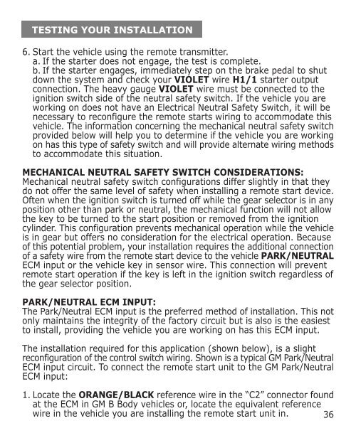
TESTING YOUR INSTALLATION<br />
6. Start the vehicle using the remote transmitter.<br />
a. If the starter does not engage, the test is complete.<br />
b. If the starter engages, immediately step on the brake pedal to shut<br />
down the system and check your VIOLET wire H1/1 starter output<br />
connection. The heavy gauge VIOLET wire must be connected to the<br />
ignition switch side of the neutral safety switch. If the vehicle you are<br />
working on does not have an Electrical Neutral Safety Switch, it will be<br />
necessary to reconfigure the remote starts wiring to accommodate this<br />
vehicle. The information concerning the mechanical neutral safety switch<br />
provided below will help you to determine if the vehicle you are working<br />
on has this type of safety switch and will provide alternate wiring methods<br />
to accommodate this situation.<br />
MECHANICAL NEUTRAL SAFETY SWITCH CONSIDERATIONS:<br />
Mechanical neutral safety switch configurations differ slightly in that they<br />
do not offer the same level of safety when installing a remote start device.<br />
Often when the ignition switch is turned off while the gear selector is in any<br />
position other than park or neutral, the mechanical function will not allow<br />
the key to be turned to the start position or removed from the ignition<br />
cylinder. This configuration prevents mechanical operation while the vehicle<br />
is in gear but offers no consideration for the electrical operation. Because<br />
of this potential problem, your installation requires the additional connection<br />
of a safety wire from the remote start device to the vehicle PARK/NEUTRAL<br />
ECM input or the vehicle key in sensor wire. This connection will prevent<br />
remote start operation if the key is left in the ignition switch regardless of<br />
the gear selector position.<br />
PARK/NEUTRAL ECM INPUT:<br />
The Park/Neutral ECM input is the preferred method of installation. This not<br />
only maintains the integrity of the factory circuit but is also is the easiest<br />
to install, providing the vehicle you are working on has this ECM input.<br />
The installation required for this application (shown below), is a slight<br />
reconfiguration of the control switch wiring. Shown is a typical GM Park/Neutral<br />
ECM input circuit. To connect the remote start unit to the GM Park/Neutral<br />
ECM input:<br />
1. Locate the ORANGE/BLACK reference wire in the “C2” connector found<br />
at the ECM in GM B Body vehicles or, locate the equivalent reference<br />
wire in the vehicle you are installing the remote start unit in. 36