- Page 1 and 2: Enano-8523T Motherboard 0-11
- Page 3 and 4: Enano-8523T Motherboard Table of Co
- Page 5 and 6: Enano-8523T Motherboard 4.2 UNPACKI
- Page 7 and 8: Enano-8523T Motherboard D.8 SPEAKER
- Page 9 and 10: Enano-8523T Motherboard Figure 6-7:
- Page 11 and 12: Enano-8523T Motherboard List of BIO
- Page 13 and 14: Enano-8523T Motherboard Chapter 1 1
- Page 15 and 16: Enano-8523T Motherboard o RSA, SHA-
- Page 17 and 18: Enano-8523T Motherboard Figure 1-2:
- Page 19 and 20: Enano-8523T Motherboard Serial Port
- Page 21 and 22: Enano-8523T Motherboard Chapter 2 2
- Page 23 and 24: Enano-8523T Motherboard • The lat
- Page 25 and 26: Enano-8523T Motherboard 2.4 Graphic
- Page 27 and 28: Enano-8523T Motherboard TPM feature
- Page 29 and 30: Enano-8523T Motherboard 2.12 USB In
- Page 31 and 32: Enano-8523T Motherboard • A3D com
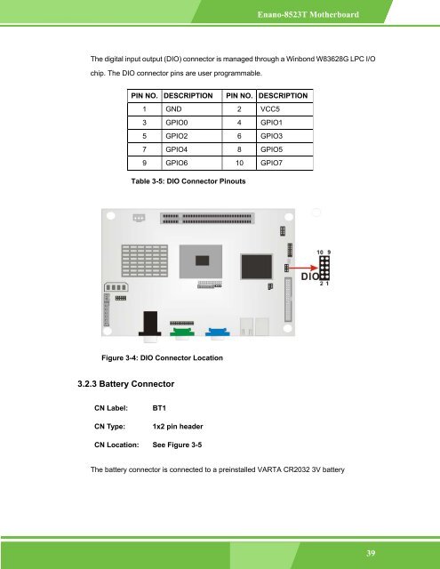
- Page 33 and 34: Enano-8523T Motherboard Chapter 3 3
- Page 35 and 36: Enano-8523T Motherboard Figure 3-2:
- Page 37: Enano-8523T Motherboard JP4 CF card
- Page 41 and 42: Enano-8523T Motherboard Figure 3-6:
- Page 43 and 44: Enano-8523T Motherboard Figure 3-8:
- Page 45 and 46: Enano-8523T Motherboard Figure 3-10
- Page 47 and 48: Enano-8523T Motherboard Figure 3-12
- Page 49 and 50: Enano-8523T Motherboard CN Type: 1x
- Page 51 and 52: Enano-8523T Motherboard Figure 3-15
- Page 53 and 54: Enano-8523T Motherboard 8 N/C 33 N/
- Page 55 and 56: Enano-8523T Motherboard PIN NO. DES
- Page 57 and 58: Enano-8523T Motherboard PIN DESCRIP
- Page 59 and 60: Enano-8523T Motherboard 3.4.1 Reset
- Page 61 and 62: Enano-8523T Motherboard Chapter 4 4
- Page 63 and 64: Enano-8523T Motherboard • allow s
- Page 65 and 66: Enano-8523T Motherboard • CPU (80
- Page 67 and 68: Enano-8523T Motherboard NOTE: When
- Page 69 and 70: Enano-8523T Motherboard Chapter 5 5
- Page 71 and 72: Enano-8523T Motherboard F2 /F3 key
- Page 73 and 74: Enano-8523T Motherboard • Process
- Page 75 and 76: Enano-8523T Motherboard BIOS Menu 3
- Page 77 and 78: Enano-8523T Motherboard Secondary S
- Page 79 and 80: Enano-8523T Motherboard per interru
- Page 81 and 82: Enano-8523T Motherboard 2 PIO mode
- Page 83 and 84: Enano-8523T Motherboard 32Bit Data
- Page 85 and 86: Enano-8523T Motherboard Parallel P
- Page 87 and 88: Enano-8523T Motherboard This option
- Page 89 and 90:
Enano-8523T Motherboard 5.3.5 ACPI
- Page 91 and 92:
Enano-8523T Motherboard NOTE: For t
- Page 93 and 94:
Enano-8523T Motherboard BIOS Menu 1
- Page 95 and 96:
Enano-8523T Motherboard The USB Mas
- Page 97 and 98:
Enano-8523T Motherboard 5.4.1 Boot
- Page 99 and 100:
Enano-8523T Motherboard Auto (Defa
- Page 101 and 102:
Enano-8523T Motherboard 5.4.3 Hard
- Page 103 and 104:
Enano-8523T Motherboard BIOS Menu 1
- Page 105 and 106:
Enano-8523T Motherboard BIOS Menu 1
- Page 107 and 108:
Enano-8523T Motherboard BIOS Menu 1
- Page 109 and 110:
Enano-8523T Motherboard The Configu
- Page 111 and 112:
Enano-8523T Motherboard The Memory
- Page 113 and 114:
Enano-8523T Motherboard 5.7 Power
- Page 115 and 116:
Enano-8523T Motherboard The Exit me
- Page 117 and 118:
Enano-8523T Motherboard Chapter 6 6
- Page 119 and 120:
Enano-8523T Motherboard Figure 6-1:
- Page 121 and 122:
Enano-8523T Motherboard Step 6: Cli
- Page 123 and 124:
Enano-8523T Motherboard Figure 6-8:
- Page 125 and 126:
Enano-8523T Motherboard Figure 6-11
- Page 127 and 128:
Enano-8523T Motherboard Figure 6-13
- Page 129 and 130:
Enano-8523T Motherboard Figure 6-16
- Page 131 and 132:
Enano-8523T Motherboard Step 4: Aft
- Page 133 and 134:
Enano-8523T Motherboard Appendix A
- Page 135 and 136:
Enano-8523T Motherboard USB Device
- Page 137 and 138:
Enano-8523T Motherboard Appendix B
- Page 139 and 140:
Enano-8523T Motherboard NOTE: When
- Page 141 and 142:
Enano-8523T Motherboard Appendix C
- Page 143 and 144:
Enano-8523T Motherboard C.3 IRQ Map
- Page 145 and 146:
Enano-8523T Motherboard Appendix D
- Page 147 and 148:
Enano-8523T Motherboard Figure D-1:
- Page 149 and 150:
Enano-8523T Motherboard Figure D-4:
- Page 151 and 152:
Enano-8523T Motherboard The Karaoke
- Page 153 and 154:
Enano-8523T Motherboard • Channel
- Page 155 and 156:
Enano-8523T Motherboard Realtek ALC
- Page 157 and 158:
Enano-8523T Motherboard D.12 HRTF D
- Page 159 and 160:
Enano-8523T Motherboard E Index 1-1
- Page 161 and 162:
Enano-8523T Motherboard D F data fl
- Page 163 and 164:
Enano-8523T Motherboard S TPM, 12,