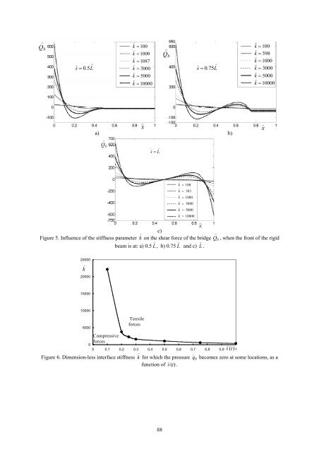
) Q b ) ) s = 0.5 L ) ) k = 100 ) k = 1000 ) k = 1087 ) k = 3000 ) k = 5000 ) k = 10000 ) Q b ) ) s = 0.75 L ) ) k = 100 ) k = 598 ) k = 1000 ) k = 3000 ) k = 5000 ) k = 10000 x a) b) ) ) s = L ) x Q b ) ) k = 100 ) k = 383 ) k = 1000 ) k = 3000 ) k = 5000 ) k = 10000 x c) Figure 5. Influence <strong>of</strong> the stiffness parameter k ) on the shear force <strong>of</strong> the bridge Q ) b , when the front <strong>of</strong> the rigid ) ) beam is at: a) 0.5 L , b) 0.75 L <strong>an</strong>d c) L ) . 25000 ) k 20000 15000 10000 5000 Compressive forces Tensile forces 0 0 0,1 0,2 0,3 0,4 0,5 0,6 0,7 0,8 0,9 s ) (t) 1 Figure 6. Dimension-less interface stiffness k ) for which the pressure q ) b becomes zero at some locations, as a function <strong>of</strong> ) s (t) . 88
5.2 FEM Analysis For the BOX cross-section <strong>of</strong> the element B22, the dimensions <strong>an</strong>d material properties given above were used, B b = 1.5676×10 13 Nm 2 , S b = 3.0793×10 11 N. The uncompressed length <strong>of</strong> the springs was 0.5 m. The displacement <strong>of</strong> the rigid beam was prescribed <strong>by</strong> applying <strong>an</strong> vertical displacement <strong>of</strong> 0.25 m at the rigid body reference node. Within the framework <strong>of</strong> the dimensional Finite Element <strong>an</strong>alysis, excellent agreement with the symbolic computations was found. Exemplary, Figure 7 shows a convergence study for the deflection <strong>an</strong>d bending moment at the mid-sp<strong>an</strong> <strong>of</strong> the fully loaded bridge, using a spring stiffness which corresponds to k ) = 5000. The Finite-Element results converge to the result <strong>of</strong> the symbolic computation with <strong>an</strong> increasing number <strong>of</strong> elements, where the speed <strong>of</strong> convergence depends on the discrete model <strong>of</strong> the spring stiffness, see relations from (28). 1,0790 1,0785 Deflection with Abaqus kFEM=kt L/N+1 Deflection with Maple7 Deflection with Abaqus kFEM=kt L/N-1 Deflection with Abaqus kFEM=kt L/N 2,60 2,55 Bending Moment with Abaqus kFEM=kt L/N+1 Bending Moment with Maple7 Bending Moment with Abaqus kFEM=kt L/N-1 Bending Moment with Abaqus kFEM=kt L/N Deflection 1,0780 1,0775 1,0770 1,07763 1,07754(Maple ) 1,07754 1,07744 Bending Moment 2,50 2,45 2,40 2,46498 2,46314 2,45884 2,45270 1,0765 2,35 1,0760 50 100 150 200 250 300 350 400 450 500 550 600 Number <strong>of</strong> Elements 2,30 50 100 150 200 250 300 350 400 450 500 550 600 Number <strong>of</strong> Elements a) b) Figure 7. The convergence <strong>of</strong> the deflection <strong>an</strong>d bending moment as a function <strong>of</strong> finite elements number <strong>an</strong>d spring stiffness. 6 Conclusions As c<strong>an</strong> be seen from Figure 2, considerable pressure concentrations take place at the ends <strong>of</strong> region covered <strong>by</strong> the rigid beam. These pressure concentrations increase with increasing dimensionless stiffness parameters k ) . Depending on the location <strong>of</strong> the front <strong>of</strong> the train, the pressure distributions become zero somewhere inside the covered (left) region <strong>of</strong> the bridge for a critical value <strong>of</strong> k ) , see Figure 6. For larger values <strong>of</strong> k ) , regions with tensile (negative) interface forces take place, <strong>an</strong>d the pressure concentrations in the compressive regions at the front ) <strong>of</strong> the rigid beam <strong>an</strong>d at the left end <strong>of</strong> the bridge become more <strong>an</strong>d more pronounced. With <strong>an</strong> increasing k , the distributions <strong>of</strong> deflection, bending moment <strong>an</strong>d shear-force deviate increasingly from their distributions known for the case <strong>of</strong> a uniform distributed load, see Figures 3-5. The rigid beam then tends to lift <strong>of</strong>f from the bridge. It was the scope <strong>of</strong> the present paper to study this effect in some detail, <strong>an</strong>d to provide corresponding information for the practical treatment <strong>of</strong> this problem. The present study refers to the linear case, in which the Winkler foundation is able to tr<strong>an</strong>smit tensile forces. When the latter c<strong>an</strong> not be tr<strong>an</strong>smitted, a non-linear treatment <strong>of</strong> the resulting contact-problem would be necessary. In the present case, we were interested in using the power <strong>of</strong> linear algebra in combination with symbolic computation to determine the behaviour in case the interface c<strong>an</strong> tr<strong>an</strong>smit compressive as well as tensile forces. Our study demonstrates that the space-wise const<strong>an</strong>t line loads, <strong>of</strong>ten used in order to model the pressure <strong>of</strong> a mass moving along a bridge, represent <strong>an</strong> idealisation that does not lay on the safe side. Acknowledgements The support <strong>of</strong> the authors E. Cojocaru <strong>an</strong>d H. Irschik <strong>by</strong> the FWF-Austri<strong>an</strong> Science Fund within the project P14866, "Vibrations <strong>of</strong> bridge without conservation <strong>of</strong> mass", is gratefully acknowledged. 89