DM7 Disassembly Tutorial - PBportal.de
DM7 Disassembly Tutorial - PBportal.de
DM7 Disassembly Tutorial - PBportal.de

You also want an ePaper? Increase the reach of your titles
YUMPU automatically turns print PDFs into web optimized ePapers that Google loves.
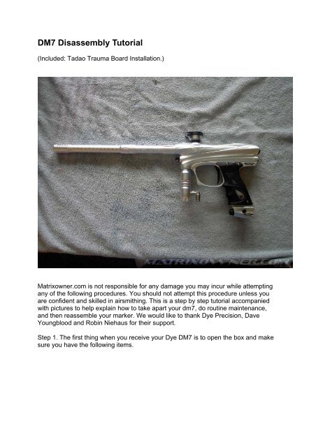
<strong>DM7</strong> <strong>Disassembly</strong> <strong>Tutorial</strong><br />
(Inclu<strong>de</strong>d: Tadao Trauma Board Installation.)<br />
Matrixowner.com is not responsible for any damage you may incur while attempting<br />
any of the following procedures. You should not attempt this procedure unless you<br />
are confi<strong>de</strong>nt and skilled in airsmithing. This is a step by step tutorial accompanied<br />
with pictures to help explain how to take apart your dm7, do routine maintenance,<br />
and then reassemble your marker. We would like to thank Dye Precision, Dave<br />
Youngblood and Robin Niehaus for their support.<br />
Step 1. The first thing when you receive your Dye <strong>DM7</strong> is to open the box and make<br />
sure you have the following items.
As usual you will need a well lit work space that inclu<strong>de</strong>s a way to keep the small<br />
screws, springs, and general pieces intact and organized. You should be able to take<br />
apart your entire dm7 with the tools provi<strong>de</strong>d by Dye. However, I recommend that<br />
you have the following:<br />
• The dye Allen set<br />
• an oring pic<br />
• a couple rags<br />
• Slick Honey<br />
• canned air<br />
• a pencil with a flat eraser<br />
I have weighed the <strong>DM7</strong> in several different variants. You can see that fully<br />
assembled with barrel, reg, asa, and macro line fittings that this marker comes in at a<br />
slim 2lb 5.8 ounces. That is truly impressive for a fully loa<strong>de</strong>d flagship gun that even<br />
has an internal lpr.
Here are a few more pics in different stages.
Step 2. Get your manual from your box and read it from cover to cover. This<br />
particular step will help you un<strong>de</strong>rstand your dm7 and it has a great troubleshooting<br />
section in the back. This will take about 20 minutes. The manual is an excellent<br />
reference tool and Dye went to a lot of trouble to make a simple and user friendly<br />
manual with fantastic pictures. Don’t be afraid to use it.
Step 3. Removal of the Fusebolt.<br />
Ok, getting started I recommend you take out the fusebolt first and clean the dye lube<br />
off. Use the ¼ Allen from your Allen set. Turn the back cap counter clockwise and<br />
pull the bolt out.
If just your back cap comes out then use something to push the rest of the bolt out<br />
from the front. If you are really good you will be able to turn the back cap just enough<br />
to release from the gun and pull out the fuse bolt without it coming apart.
Take the fuse bolt apart.<br />
Unscrew the rear section of the bolt with the top hat. Then unscrew the top hat from<br />
the beer can. You should have 4 pieces to the bolt. The bolt itself, the beer can, the<br />
top hat, and the end cap.<br />
You can replace the #17 orings in the beer can and the top hat with Buena 017 BN70<br />
orings. These are the black orings. These orings can be purchased at the following<br />
locations.<br />
http://www.compulsivepaintball.com/<br />
http://www.air-oil.com/<br />
http://www.mcmaster.com/<br />
Using an o-ring removal tool remove the 017 o-rings from the top hat and beer can<br />
and replace them with Buena orings.
Bolt Maintenance<br />
Quoted from Macky and agreed upon by the Agents at MO.<br />
“Lets talk lube first, preferred choice of Lube is Slick honey. If you do not have Slick<br />
Honey, a mix of DOW33 with Gold Cup oil is recommen<strong>de</strong>d. 3 parts DOW33 to 1 part<br />
Gold Cup works great. It should have the consistency of Pudding. Straight DOW33 is<br />
OK too but requires more frequent cleaning.”<br />
“I know a lot of people said slick honey does not perform well in the cold. I have<br />
found that this is mostly due to the over lubing with Slick Honey. I have played plenty<br />
in the cold and I still use Slick Honey with no drop off. In the picture below is what I<br />
will refer to as a DAB of Lube. Sorry it’s the best technical term I can think of right<br />
now. My DAB might be a little bigger because I have big hands so use best<br />
judgment.”<br />
“This by far will make your bolt butter smooth, allowing for lower LPR and Dwell<br />
settings. DYE uses the 017 UR70 (Urethane) o-rings because a lot of <strong>de</strong>bris/paint/dirt<br />
can get in the breech and cause the o-ring on the beer can to leak. They did not want<br />
to get a ton of repairs to replace an o-ring. I have not found the need for a tougher o-<br />
ring. So if the Buna makes the Bolt smoother, then I am using it.”<br />
Now to actually lubing the bolt. Take (1) DAB of lube and lube the Bolt sail o-rings
and the metal in front and behind the bolt sail.<br />
Next take (1) DAB of lube and lube the bolt plunger.<br />
Next take (1) DAB of lube and lube the beer can, start with the 017 O-ring and then<br />
coat the inner surface. Use the excess lube and apply to the outer #20 o-rings. It<br />
won't be that much but you don't need a lot.
Next take (1) DAB of lube and lube the top hat start with the 017 o-ring and the inner<br />
surface of the top hat.<br />
If nee<strong>de</strong>d just get a touch more lube and lube the 013 o-ring, then use the excess<br />
and lube the outer #20 and the portion of the bolt stem that the 013 o-ring makes<br />
contact.<br />
Use the excess lube on your finger to lube the #20 o-rings on the Back cap.<br />
Set your Fusebolt asi<strong>de</strong> and out of the way. It will be one of the last pieces you put in<br />
your gun during reassembly.<br />
Step 4 . Take out your 1/16 Allen wrench. Simply insert the Allen wrench into the hole<br />
in the eye cover to access the retaining screw.<br />
As you back the screw out, the plate will be pushed up. You will now have access to<br />
the <strong>de</strong>tents, <strong>de</strong>tent springs, the eye and eye wire.
You want to take out the eyes and the <strong>de</strong>tents. Keep those little springs safe. I<br />
<strong>de</strong>ci<strong>de</strong>d to do this just in case I acci<strong>de</strong>ntally pull on the eye wires during disassembly<br />
of the body. This will allow the eyes to move a little and hopefully not get yanked on<br />
and cause them to crimp or break.
[b]Step 5. [/B Taking off the Ultralight grip frame.<br />
You will first need to take off the UL sticky grips. Use a 3/32 Allen to remove all six<br />
screw from the grip.
Next you will need to disconnect the solenoid wire harness and the eye wire harness<br />
so they do not rip or break when pulling off the frame.
Now you will need to pry out the battery. Do this from the bottom of the battery so you<br />
do not put undue stress on the terminals. Just gently press it out.
I want to quickly point out the unique way that Dye incorporates their built in dove tail<br />
rail system. They have mounted a cam that can be accessed through the grip to<br />
tighten the asa.
Step 6. Removing the dm7 board.<br />
Using a small Phillips screwdriver carefully and slowly remove the two screws holding<br />
the frame. When that is done gently pull the board out by touching only the very top<br />
of the board. Do not touch the board at any time. Any static electricity in you your<br />
body could fry your board. When you get the board up just lightly grasp the si<strong>de</strong>s and<br />
put the board in a place free of static charge. Once the board is out your on/off and<br />
eye buttons will come out easily. Put these in a safe place.
Remove the Hyper 2 to get it out of the way.
Using your 3/32 Allen loosen the front frame screw by turning it counter clockwise.<br />
Once you feel it break loose just turn it 1 full turn counter clockwise. You do not want<br />
it to come completely loose.
Using your 3/32 Allen loosen the rear frame screw by turning it counter clockwise.<br />
Take this screw out and place it in a safe place.
Now carefully remove the Ultralight grip frame making sure not to pull on the solenoid<br />
and eye wires.
Step 7. Removing the trigger.<br />
The first thing you need to do is remove the trigger pin. This is the pin that the trigger<br />
pivots on. You will be glad to know that Dye has supplied the threa<strong>de</strong>d trigger pin that<br />
is now standard on all UL frames. It is threa<strong>de</strong>d on one si<strong>de</strong> so you can unscrew it<br />
out and then gently poke it out with a punch or something small.
Next you will need to take out the adjustment screws. The screw with fewer threads<br />
will always be the forward screw.
Gently sli<strong>de</strong> the trigger out of the top of the frame after you have taken the tension<br />
spring out from behind the trigger. You can adjust the tension spring from the front of<br />
the trigger bla<strong>de</strong>. This is also a new feature to matrixes. Instead of changing springs<br />
you can now adjust the tension. If you want it light unscrew the set screw counter<br />
clockwise, and do the reverse if you want it tighter. I found no need to take the spring<br />
out now.
Step 8. OPTIONAL. Removing your ON/OFF.<br />
I do not recommend this step unless you are having a leaking issue with your on/off.<br />
Don’t mess with it if it aint broke.<br />
First you will need to take out the frame screw. Then you will need to loosen and take<br />
out the on/off set screw. Once you have done this you can pull the on/off out of the<br />
front of the marker. If there is a leak it is most likely the oring that lies on the on/off<br />
versus the two 009 BN70 orings that wrap around it. The oring that lies on the on/off<br />
is a 009 UR90.<br />
Step 8. ] Taking out the self cleaning acrylic insert.<br />
Remember some of the problems with the first attempt with a self cleaning gun<br />
system? The DM6 was the first gun ever to use this type of technology. It<br />
incorporated individual acrylic eye inserts that were radiused flush with the insi<strong>de</strong> of<br />
the breech.
One of the problems was securing the inserts so they sat flush with the insi<strong>de</strong> of the
eech and didn’t tear up the bolt tip oring. Dye hea<strong>de</strong>d the i<strong>de</strong>as of Macky and some<br />
of the members here and installed an oring behind the insert to push them into their<br />
slot correctly.<br />
Well, Dye <strong>de</strong>ci<strong>de</strong>d to go back to the drawing board and improve upon this <strong>de</strong>sign.<br />
They actually completely re-<strong>de</strong>signed the entire system. I think the answer they came<br />
up with was brilliant for two reasons. 1. They created a simple insert that sli<strong>de</strong>s into<br />
the breech and is held there by an oring, the barrel, and the <strong>de</strong>tents. 2. It is easily<br />
replaceable if it gets scratched or broken.<br />
Now the eyes are completely protected and should last 2-3 times longer because we<br />
won’t be cleaning them, handling them, or scratching them. To get this insert out, just<br />
take off the barrel and put your finger in the breech. Press the <strong>de</strong>tents in and sli<strong>de</strong><br />
the insert out while it is stuck on your finger.
Step 9. Removing the solenoid/ explo<strong>de</strong>d view of solenoid.<br />
I do not recommend you take out your solenoid and/or take it apart. You are asking<br />
for a world of trouble and Dye consi<strong>de</strong>rs this a breach of warranty. In fact the pictures<br />
you see here and on some of the other tutorials that use this new solenoid are the<br />
exact same ones from the dm6 tutorial. I find there is no need to take this particular<br />
solenoid apart every time I explain the process for a new mo<strong>de</strong>l of marker. Therefore,<br />
I took this particular solenoid mo<strong>de</strong>l apart once for posterity, but I follow my own “rule<br />
of thumb,” “Don’t take it apart unless it is an emergency.” I have inclu<strong>de</strong>d the steps in<br />
this tutorial so everyone can see how it is done and what the pieces of the new<br />
solenoid looks like. If you take this solenoid apart you will breach your warranty. This<br />
is why you should not mess with it. I will post the pics. They are self explanatory so<br />
there will be no text instruction on this step.
That black rubber thing is the manifold gasket. Make sure you lube it lightly and seat<br />
it back onto the solenoid before you put the solenoid back in. Most people think this<br />
is the seal that leaks when their solenoid is leaking air. 99 times out of a 100 this seal<br />
is perfectly good. That leak is caused by the #15 bolt sail oring or one of the beer can<br />
orings. Not the manifold gasket. Just a FYI.
Step 10. Taking out the lpr and cleaning it.
Take off the lpr back cover behind the marker using a 1/4” Allen wrench.
Unscrew the lpr set screw using a 5/64 Allen wrench.
Pull out the lpr by screwing a 10/32 threa<strong>de</strong>d rod or screw into the seal retainer, the<br />
brass piece, and then pull it out.
Now you need to take this lpr apart and clean all the dye lube of off it and then relube<br />
it with slick honey or some other accepted matrix lube. First you need to push<br />
out the piston from the casing. You can do this safely by using a pencil eraser and<br />
pushing the piston out. You do not want to use something hard to do this as you will<br />
damage the piston and it won’t seal against the reg seat, (main seal.) When you get<br />
the piston out, you need to pull out the spring also. Clean out the reg housing with a<br />
cue tip and get the green gunk out of there.<br />
Using (1) DAB of lube the piston o-ring and the rest of the piston and the inner<br />
surface of the LPR housing. Then apply (1) DAB of lube to the spring. Place spring<br />
back on piston and re-insert into LPR housing.
CONGRADULATIONS! YOU HAVE NOW TAKEN YOUR <strong>DM7</strong> COMPLETELY<br />
APART. JUST REVERSE YOUR STEPS AND GO SLOWLY.<br />
REASSEMBLY.<br />
Step 11.<br />
Start with the lpr. Once it is lubed correctly just put the spring back in the housing.<br />
Sli<strong>de</strong> the piston back through the spring, and then screw in the brass seal retainer.<br />
Insert the lpr back into the body of the gun making sure the in<strong>de</strong>ntation of the lpr<br />
matches up with the set screw hole. Push in the lpr and tighten down the set screw.<br />
Do not torque on the set screw.
Your solenoid and on/off should already be in the body since you did not take them<br />
out. Right? (Wink!)<br />
Step 12 . Install the acrylic insert, ball <strong>de</strong>tents, and eyes back into the body. Make<br />
sure the large hole in the insert is facing up. I am pointing to the <strong>de</strong>tent hole and you<br />
can see the large opening facing up. Then press the eyes back into place. Once this<br />
is done put the <strong>de</strong>tent in its hole and the spring. Put the eye covers on and tighten<br />
down.
Step 13 Putting Ultralight trigger frame back together.<br />
You will need to reinstall the trigger pin and the adjustment screws. Make sure the<br />
adjustment screw that has the few threads is in the farthest hole to the right. Once<br />
you have the trigger in you can add the spring behind the trigger. You will need to<br />
completely reset your trigger to how you like it. I suggest you do this once you have<br />
the gun together and you can hear the solenoid click when the trigger actuates. As<br />
you will notice I had an extra dust silver UL frame trigger so I am installing it back in<br />
instead of the black. For some reason, Scarlet and Silver sounds like a good new<br />
color scheme.
Next you will need to put in the on/off-eye buttons before you put in the board.
Once this is done, then install the board by holding on the edges of the board and<br />
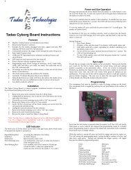
laying it down in the frame gently. I am installing a new Tadao Technologies M7<br />
Trauma Board into this gun. I packed the stock UL board in a static free baggie and<br />
stored it away in the dark somewhere safe. This board is like adding a jet engine to<br />
an Indy car! It is just sick and probably not even fair. This board has unlimited<br />
settings and allows more power to be diverted to the solenoid so it runs faster and<br />
more consistently making this dm7 incredibly accurate and fast. Using a small<br />
screwdriver, screw the board down DO NOT TIGHTEN VERY HARD. JUST<br />
TIGHTEN THE BOARD SCREWS SO THEY ARE SNUG.
Make sure you get the micro switch spring behind the trigger. Be gentle! Take your<br />
time and don’t force anything. This is a $150 jet engine here, you don’t want it to<br />
explo<strong>de</strong>!
Next you can put the frame back on the body. Make sure you do not pinch the<br />
solenoid wires and the eye wires. Sli<strong>de</strong> the frame un<strong>de</strong>r the front frame screw near<br />
the asa and then tighten down both frame screws.
Plug the solenoid harness and the eye harness back in carefully.
Step 14 Put your ASA back onto the dovetail.
Now put your grips back on and your hyper II back on and put your fuse bolt back in<br />
and you are finished!!! Good luck and don’t try this at home without matrixowner!!