Seismic Design of Tunnels - Parsons Brinckerhoff
Seismic Design of Tunnels - Parsons Brinckerhoff
Seismic Design of Tunnels - Parsons Brinckerhoff

You also want an ePaper? Increase the reach of your titles
YUMPU automatically turns print PDFs into web optimized ePapers that Google loves.
1991 William Barclay <strong>Parsons</strong> Fellowship<br />
<strong>Parsons</strong> Brinckerh<strong>of</strong>f<br />
Monograph 7<br />
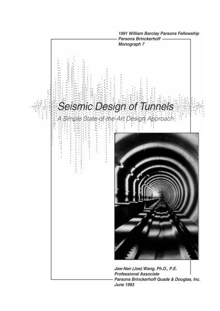
<strong>Seismic</strong> <strong>Design</strong> <strong>of</strong> <strong>Tunnels</strong><br />
A Simple State-<strong>of</strong>-the-Art <strong>Design</strong> Approach<br />
Jaw-Nan (Joe) Wang, Ph.D., P.E.<br />
Pr<strong>of</strong>essional Associate<br />
<strong>Parsons</strong> Brinckerh<strong>of</strong>f Quade & Douglas, Inc.<br />
June 1993
First Printing 1993<br />
Copyright © Jaw-Nan Wang and <strong>Parsons</strong> Brinckerh<strong>of</strong>f Inc.<br />
All rights reserved. No part <strong>of</strong> this work covered by the copyright thereon may be<br />
reproduced or used in any form or by any means — graphic, electronic, or mechanical,<br />
including photocopying, recording, taping, or information storage or retrieval systems —<br />
without permission <strong>of</strong> the publisher.<br />
Published by<br />
<strong>Parsons</strong> Brinckerh<strong>of</strong>f Inc.<br />
One Penn Plaza<br />
New York, New York
CONTENTS<br />
Foreword<br />
ix<br />
1.0 Introduction 1<br />
1.1 Purpose 3<br />
1.2 Scope <strong>of</strong> this Study 4<br />
1.3 Background 4<br />
Importance <strong>of</strong> <strong>Seismic</strong> <strong>Design</strong> 4<br />
<strong>Seismic</strong> <strong>Design</strong> before the ‘90s 5<br />
1.4 General Effects <strong>of</strong> Earthquakes 7<br />
Ground Shaking 7<br />
Ground Failure 8<br />
1.5 Performance Record in Earthquakes 8<br />
2.0 <strong>Seismic</strong> <strong>Design</strong> Philosophy for Tunnel Structures 13<br />
2.1 <strong>Seismic</strong> <strong>Design</strong> vs. Conventional <strong>Design</strong> 15<br />
2.2 Surface Structures vs. Underground Structures 15<br />
Surface Structures 15<br />
Underground Structures 16<br />
<strong>Design</strong> and Analysis Approaches 16<br />
2.3 <strong>Seismic</strong> <strong>Design</strong> Philosophies for Other Facilities 17<br />
Bridges and Buildings 17<br />
Nuclear Power Facilities 17<br />
Port and Harbor Facilities 18<br />
Oil and Gas Pipeline Systems 18<br />
2.4 Proposed <strong>Seismic</strong> <strong>Design</strong> Philosophy for Tunnel Structures 19<br />
Two-Level <strong>Design</strong> Criteria 19<br />
Loading Criteria 20<br />
3.0 Running Line Tunnel <strong>Design</strong> 25<br />
3.1 Overview 27<br />
3.2 Types <strong>of</strong> Deformations 27<br />
Axial and Curvature Deformations 27<br />
Ovaling or Racking Deformations 29<br />
i
3.3 Free-Field Axial and Curvature Deformations 31<br />
Background 31<br />
A Practical Approach to Describing Ground Behavior 31<br />
Simplified Equations for Axial Strains and Curvature 33<br />
3.4 <strong>Design</strong> Conforming to Free-Field Axial and Curvature Deformations 35<br />
Background and Assumptions 35<br />
<strong>Design</strong> Example 1: The Los Angeles Metro 35<br />
Applicability <strong>of</strong> the Free-Field Deformation Approach 37<br />
3.5 Tunnel-Ground Interaction 37<br />
Simplified Interaction Equations 38<br />
<strong>Design</strong> Example 2: A Linear Tunnel in S<strong>of</strong>t Ground 43<br />
3.6 Special Considerations 48<br />
Unstable Ground 48<br />
Faulting 48<br />
Abrupt Changes in Structural Stiffness or Ground Conditions 49<br />
4.0 Ovaling Effect on Circular <strong>Tunnels</strong> 53<br />
4.1 Ovaling Effect 55<br />
4.2 Free-Field Shear Deformations 55<br />
Simplified Equation for Shear Deformations 56<br />
4.3 Lining Conforming to Free-Field Shear Deformations 58<br />
4.4 Importance <strong>of</strong> Lining Stiffness 60<br />
Compressibility and Flexibility Ratios 60<br />
Example 1 61<br />
Example 2 62<br />
Summary and Conclusions 63<br />
4.5 Lining-Ground Interaction 64<br />
Closed Form Solutions 64<br />
Numerical Analysis 76<br />
Results and Recommendations 76<br />
5.0 Racking Effect on Rectangular <strong>Tunnels</strong> 83<br />
5.1 General 85<br />
5.2 Racking Effect 86<br />
5.3 Dynamic Earth Pressure Methods 87<br />
ii
Mononobe-Okabe Method 87<br />
Wood Method 87<br />
Implications for <strong>Design</strong> 88<br />
5.4 Free-Field Racking Deformation Method 88<br />
San Francisco BART 90<br />
Los Angeles Metro 90<br />
Flexibility vs. Stiffness 90<br />
Applicability <strong>of</strong> the Free-Field Racking Method 92<br />
Examples 92<br />
5.5 Tunnel-Ground Interaction Analysis 96<br />
Factors Contributing to the Soil-Structure Interaction Effect 100<br />
Method <strong>of</strong> Analysis 100<br />
Flexibility Ratio for Rectangular <strong>Tunnels</strong> 102<br />
Results <strong>of</strong> Analysis 112<br />
5.6 Recommended Procedure: Simplified Frame Analysis Models 122<br />
Step-by-Step <strong>Design</strong> Procedure 122<br />
Verification <strong>of</strong> the Simplified Frame Models 128<br />
5.7 Summary <strong>of</strong> Racking <strong>Design</strong> Approaches 133<br />
6.0 Summary 135<br />
Vulnerability <strong>of</strong> Tunnel Structures 137<br />
<strong>Seismic</strong> <strong>Design</strong> Philosophy 137<br />
Running Line Tunnel <strong>Design</strong> 138<br />
Ovaling Effect on Circular <strong>Tunnels</strong> 139<br />
Racking Effect on Rectangular <strong>Tunnels</strong> 139<br />
References 141<br />
iii
LIST OF FIGURES<br />
Figure Title Page<br />
1 Ground Response to <strong>Seismic</strong> Waves 6<br />
2 Damage Statistics 11<br />
3 Axial and Curvature Deformations 28<br />
4 Ovaling and Racking Deformations 30<br />
5 Geometry <strong>of</strong> a Sinusoidal Shear Wave Oblique to Axis <strong>of</strong> Tunnel 32<br />
6 Sectional Forces Due to Curvature and Axial Deformations 39<br />
7 Free-Field Shear Distortions <strong>of</strong> Ground Under Vertically Propagating<br />
Shear Waves 57<br />
8 Free-Field Shear Distortion <strong>of</strong> Ground (Non-Perforated Medium) 59<br />
9 Shear Distortion <strong>of</strong> Perforated Ground (Cavity In-Place) 59<br />
10 Lining Response Coefficient, K 1 (Full-Slip Interface) 66<br />
11 Lining Response Coefficient, K 1 (Full-Slip Interface) 67<br />
12 Lining Response (Thrust) Coefficient, K 2 (No-Slip Interface) 69<br />
13 Lining Response (Thrust) Coefficient, K 2 (No-Slip Interface) 70<br />
14 Lining Response (Thrust) Coefficient, K 2 (No-Slip Interface) 71<br />
15 Normalized Lining Deflection (Full-Slip Interface) 73<br />
16 Normalized Lining Deflection (Full-Slip Interface) 74<br />
17 Finite Difference Mesh (Pure Shear Condition) 75<br />
18 Influence <strong>of</strong> Interface Condition on Bending Moment 78<br />
19 Influence <strong>of</strong> Interface Condition on Lining Deflection 80<br />
iv
Figure Title Page<br />
20 Typical Free-Field Racking Deformation<br />
Imposed on a Buried Rectangular Frame 89<br />
21 Structure Stability for Buried Rectangular Frames 91<br />
22 Soil-Structure System Analyzed in Example 93<br />
23 Subsurface Shear Velocity Pr<strong>of</strong>iles 95<br />
24 Free-Field Shear Deformations<br />
(from Free-Field Site Response Analysis, SHAKE) 97<br />
25 Structure Deformations vs. Free-Field Deformations, Case I<br />
(from Soil/Structure Interaction Analysis, FLUSH) 98<br />
26 Structure Deformations vs. Free-Field Deformations, Case ll<br />
(from Soil/Structure Interaction Analysis, FLUSH) 99<br />
27 Typical Finite Element Model<br />
(for Structure Type 2) 103<br />
28 Earthquake Accelerograms on Rock<br />
West Coast 104<br />
Northeast 105<br />
29 <strong>Design</strong> Response Spectra on Rock<br />
(West Coast Earthquake vs. Northeast Earthquake) 106<br />
30 Types <strong>of</strong> Structure Geometry Used in the Study 107<br />
31 Relative Stiffness Between Soil and a Rectangular Frame 108<br />
32 Determination <strong>of</strong> Racking Stiffness 111<br />
33 Normalized Racking Deflections<br />
(for Cases 1 through 25) 115<br />
34 Normalized Structure Deflections 116<br />
35 Normalized Structure Deflections 117<br />
v
Figure Title Page<br />
36 Effect <strong>of</strong> Embedment Depth on Racking Response Coefficient, R 121<br />
37 Normalized Structure Deflections 124<br />
38 Simplified Frame Analysis Models 127<br />
39 Moments at Ro<strong>of</strong>-Wall Connections<br />
Concentrated Force Model<br />
(for Cases 1 through 5) 129<br />
40 Moments at Invert-Wall Connections<br />
Concentrated Force Model<br />
(for Cases 1 through 5) 130<br />
41 Moments at Ro<strong>of</strong>-Wall Connections<br />
Triangular Pressure Distribution Model<br />
(for Cases 1 through 5) 131<br />
42 Moments at Invert-Wall Connections<br />
Triangular Pressure Distribution Model<br />
(for Cases 1 through 5) 132<br />
vi
LIST OF TABLES<br />
Table Title Page<br />
1 Free-Field Ground Strains 34<br />
2 Cases Analyzed by Finite Difference Modeling 77<br />
3 Influence <strong>of</strong> Interface Conditions on Thrust 81<br />
4 Cases Analyzed by Dynamic Finite Element Modeling 113<br />
5 Cases Analyzed to Study the Effect <strong>of</strong> Burial Depth 120<br />
6 Cases Analyzed to Study the Effect <strong>of</strong> Stiff Foundation 123<br />
7 <strong>Seismic</strong> Racking <strong>Design</strong> Approaches 134<br />
vii
viii
FOREWORD<br />
For more than a century, <strong>Parsons</strong> Brinckerh<strong>of</strong>f (PB) has been instrumental in<br />
advancing state-<strong>of</strong>-the-art design and construction <strong>of</strong> underground structures, and the<br />
fields <strong>of</strong> seismic design and earthquake engineering are no exceptions. Almost three<br />
decades ago PB’s engineers pioneered in these fields in the design and construction <strong>of</strong><br />
the San Francisco BART system, whose toughness during earthquakes, including the<br />
recent Loma Prieta event, has been amply tested. Recently, PB developed state-<strong>of</strong>-theart,<br />
two-level seismic design philosophy in its ongoing Los Angeles Metro and Boston<br />
Central Artery/Third Harbor Tunnel projects, taking into account both performance-level<br />
and life-safety-level earthquakes.<br />
This monograph represents PB’s continuous attempts in the seismic design and<br />
construction <strong>of</strong> underground structures to:<br />
• Improve our understanding <strong>of</strong> seismic response <strong>of</strong> underground structures<br />
• Formulate a consistent and rational seismic design procedure<br />
Chapter 1 gives general background information including a summary <strong>of</strong> earthquake<br />
performance data for underground structures.<br />
Chapter 2 presents the seismic design philosophy for tunnel structures and the<br />
rationale behind this philosophy. Differences in seismic considerations between surface<br />
structures and underground structures, and those between a seismic design and a static<br />
design are also discussed.<br />
Chapter 3 focuses on the seismic design considerations in the longitudinal direction <strong>of</strong><br />
the tunnels. Axial and curvature deformations are the main subjects. The free-field<br />
deformation method and the methods accounting for tunnel-ground interaction effects are<br />
reviewed for their applicability.<br />
Chapter 4 takes a look at the ovaling effect on circular tunnel linings. Closed-form<br />
solutions considering soil-lining interaction effects are formulated and presented in the<br />
form <strong>of</strong> design charts to facilitate the design process.<br />
Chapter 5 moves to the evaluation <strong>of</strong> racking effect on cut-and-cover rectangular<br />
tunnels. This chapter starts with a review <strong>of</strong> various methods <strong>of</strong> analysis that are currently<br />
in use, followed by a series <strong>of</strong> dynamic finite-element analyses to study the various factors<br />
influencing the tunnel response. At the end, simplified frame analysis models are<br />
proposed for this evaluation.<br />
Chapter 6 ends this monograph with a general summary.<br />
ix
Acknowledgments<br />
I wish to express my thanks to the Career Development Committee and Paul H.<br />
Gilbert, the original initiator <strong>of</strong> the William Barclay <strong>Parsons</strong> Fellowship Program, for<br />
selecting my proposal and providing continuous support and guidance throughout this<br />
study. Thanks are also due to the Board <strong>of</strong> Directors <strong>of</strong> <strong>Parsons</strong> Brinckerh<strong>of</strong>f Inc. for<br />
making the growth and flowering <strong>of</strong> an engineer’s idea possible.<br />
The fruitful results <strong>of</strong> this exciting study would never have been possible without<br />
technical guidance from three individuals — my fellowship mentors, Dr. George Munfakh<br />
and Dr. Birger Schmidt, and the technical director <strong>of</strong> underground structures, Dr. James<br />
E. Monsees. Their constant critiques and advice were sources <strong>of</strong> inspiration and<br />
motivation.<br />
Appreciation is due also to Tom Kuesel, who gave constructive technical comments<br />
on the content <strong>of</strong> this study, and to Tim Smirn<strong>of</strong>f, who provided much <strong>of</strong> the tunnel<br />
structural data <strong>of</strong> the LA Metro project. Ruchu Hsu and Rick Mayes deserve my thanks<br />
for generously giving their time and comments on the draft <strong>of</strong> this monograph. Gratitude<br />
is <strong>of</strong>fered to many other individuals for numerous technical discussions on real world<br />
seismic design issues for the ongoing Central Artery/Third Harbor Tunnel project and the<br />
Portland Westside LRT project. They include: Louis Silano, Vince Tirolo, Anthony<br />
Lancellotti, Dr. Sam Liao, Brian Brenner, Alexander Brudno, Mike Della Posta, Dr. Edward<br />
Kavazanjian, Richard Wilson, and many others.<br />
Very special thanks to Willa Garnick for her exquisite editing <strong>of</strong> the manuscript, and<br />
to Randi Aronson who carefully pro<strong>of</strong>read the final draft <strong>of</strong> the monograph. Their wonderful<br />
work gave this fellowship study a beautiful finish. I also acknowledge the support<br />
and contribution <strong>of</strong> personnel <strong>of</strong> the New York <strong>of</strong>fice Graphics Department, particularly<br />
Pedro Silva who prepared the graphics and tables and laid out the text.<br />
I simply could not put a period to this study without expressing thanks to my wife<br />
Yvonne Yeh, my son Clinton and my daughter Jolene. Their sacrificing support <strong>of</strong> my<br />
work through many late nights and weekends contributed the greatest part to this<br />
monograph.<br />
Jaw-Nan (Joe) Wang, Ph.D., P.E.<br />
Pr<strong>of</strong>essional Associate<br />
<strong>Parsons</strong> Brinckerh<strong>of</strong>f Quade & Douglas, Inc.<br />
June 1993<br />
x
1.0 INTRODUCTION<br />
1
1.0 INTRODUCTION<br />
1.1 Purpose<br />
The purpose <strong>of</strong> this research study was to develop a rational and consistent seismic<br />
design methodology for lined transportation tunnels that would also be applicable to other<br />
underground lined structures with similar characteristics. The results presented in this<br />
report provide data for simple and practical application <strong>of</strong> this methodology.<br />
While the general public is <strong>of</strong>ten skeptical about the performance <strong>of</strong> underground<br />
structures, tunnel designers know that underground structures are among the safest<br />
shelters during earthquakes, based primarily on damage data reported in the past. Yet<br />
one certainly would not want to run away from a well designed building into a buried tunnel<br />
when seismic events occur if that tunnel had been built with no seismic considerations.<br />
Most tunnel structures were designed and built, however, without regard to seismic<br />
effects. In the past, seismic design <strong>of</strong> tunnel structures has received considerably less<br />
attention than that <strong>of</strong> surface structures, perhaps because <strong>of</strong> the conception about the<br />
safety <strong>of</strong> most underground structures cited above. In fact, a seismic design procedure<br />
was incorporated into a tunnel project for the first time in the 1960s by PB engineers.<br />
In recent years, however, the enhanced awareness <strong>of</strong> seismic hazards for<br />
underground structures has prompted an increased understanding <strong>of</strong> factors influencing<br />
the seismic behavior <strong>of</strong> underground structures. Despite this understanding, significant<br />
disparity exists among engineers in design philosophy, loading criteria, and methods <strong>of</strong><br />
analysis.<br />
Therefore, this study, geared to advance the state <strong>of</strong> the art in earthquake engineering<br />
<strong>of</strong> transportation tunnels, has the following goals:<br />
• To maintain a consistent seismic design philosophy and consistent design criteria<br />
both for underground structures and other civil engineering facilities.<br />
• To develop simple yet rational methods <strong>of</strong> analysis for evaluating earthquake effects<br />
on underground structures. The methodology should be consistent for structures with<br />
different section geometries.<br />
3
1.2 Scope <strong>of</strong> this Study<br />
The work performed to achieve these goals consisted <strong>of</strong>:<br />
• A summary <strong>of</strong> observed earthquake effects on underground structures.<br />
• A comparison <strong>of</strong> seismic design philosophies for underground structures and other<br />
civil engineering facilities. Based on this comparison, seismic design criteria were<br />
developed for underground tunnels.<br />
• A quantitative description <strong>of</strong> ground behavior during traveling seismic waves. Various<br />
modes <strong>of</strong> ground deformations and their engineering implications for tunnel design<br />
are discussed.<br />
• A review <strong>of</strong> current seismic design methodology for both circular mined tunnels and<br />
cut-and-cover rectangular tunnels. Examples were used to study the applicability <strong>of</strong><br />
these conventionally used methods <strong>of</strong> analysis.<br />
• The development <strong>of</strong> a refined (yet simple) method for evaluating the earthquake<br />
ovaling effect on circular linings. This method considers the soil-structure interaction<br />
effects and is built from a theory that is familiar to most mining/underground<br />
engineers. To ease the design process, a series <strong>of</strong> design charts was developed,<br />
and these theoretical results were further validated through a series <strong>of</strong> numerical<br />
analyses.<br />
• The development <strong>of</strong> a simplified frame analysis model for evaluating the earthquake<br />
racking effect on cut-and-cover rectangular tunnels. During the process <strong>of</strong> this<br />
development, an extensive study using dynamic finite-element, soil-structure<br />
interaction analyses was conducted to cover a wide range <strong>of</strong> structural, geotechnical<br />
and ground motion parameters. The purpose <strong>of</strong> these complex and time consuming<br />
analyses was not to show the elegance <strong>of</strong> the mathematical computations. Rather,<br />
these analyses were used to generate design data that could be readily incorporated<br />
into the recommended simplified frame analysis model.<br />
1.3 Background<br />
Importance <strong>of</strong> <strong>Seismic</strong> <strong>Design</strong><br />
One <strong>of</strong> the significant aspects <strong>of</strong> the 1989 Loma Prieta earthquake in the San<br />
Francisco area was its severe impact on the aboveground transportation system:<br />
4
• The collapse <strong>of</strong> the I-880 viaduct claimed more than 40 lives.<br />
• The direct damage costs to the transportation facilities alone totalled nearly $2 billion<br />
(Werner and Taylor, 1990).<br />
• The indirect losses were several times greater as a result <strong>of</strong> major disruptions <strong>of</strong><br />
transportation, particularly on the San Francisco-Oakland Bay Bridge and several<br />
major segments <strong>of</strong> the Bay area highway system.<br />
The San Francisco Bay Area Rapid Transit (BART) subway system was found to be<br />
one <strong>of</strong> the safest places during the event, and it became the only direct public<br />
transportation link between Oakland and San Francisco after the earthquake. Had BART<br />
been damaged and rendered inoperative, the consequences and impact on the Bay area<br />
would have been unthinkable.<br />
The 60-mile BART system was unscathed by the earthquake because PB engineers<br />
had the foresight 30 years ago to incorporate state-<strong>of</strong>-the-art seismic design criteria in their<br />
plans for the subway tunnels (SFBARTD, 1960; Kuesel, 1969; and Douglas and Warshaw,<br />
1971). The Loma Prieta earthquake proved the worth <strong>of</strong> their pioneering efforts.<br />
<strong>Seismic</strong> <strong>Design</strong> Before the ‘90s<br />
Based on the performance record, it is undoubtedly fair to say that underground<br />
structures are less vulnerable to earthquakes than surface structures (Dowding and<br />
Rozen, 1978; Rowe, 1992). Interestingly, some tunnels and shafts built without special<br />
earthquake provisions have survived relatively strong earthquakes in the past — for<br />
example, the Mexico City subway during the 1985 Mexico City earthquake. On the other<br />
hand, some underground structures have been damaged severely in other events (see<br />
Section 1.5).<br />
Limited progress has been made in seismic design methodology for underground<br />
tunnels since the work for BART, possibly because <strong>of</strong> favorable performance data, and<br />
limited research work has been done toward a practical solution. The lack <strong>of</strong> a rational<br />
methodology for engineers and the nonexistence <strong>of</strong> applicable codes has led to widely<br />
varied measures taken by different engineers. For example:<br />
• Some ignore seismic effects and fail to check the resistance <strong>of</strong> the structures to<br />
earthquakes, even in highly seismic areas.<br />
• Others conduct their seismic design for underground structures using the same<br />
methodology developed for aboveground structures, without recognizing that<br />
underground structures are constrained by the surrounding medium.<br />
5
Figure 1.<br />
Ground Response to <strong>Seismic</strong> Waves<br />
(Source: Bolt, 1978)<br />
6
<strong>Design</strong> based on such inappropriate measures may lead to the construction <strong>of</strong> unsafe<br />
structures or structures that are too conservatively designed.<br />
Although the progress <strong>of</strong> underground seismic design methodology is lagging, the<br />
earthquake awareness in the country is not. Recent discoveries in seismology, geology<br />
and geotechnical engineering have led to the belief that earthquake hazard is no longer<br />
only a California problem. Many regions throughout the United States, Puerto Rico and the<br />
Virgin Islands are now known to have the potential for tremors <strong>of</strong> similar or larger<br />
magnitude than that <strong>of</strong> the Loma Prieta. This situation demands rethinking <strong>of</strong> the current<br />
seismic design practice for our underground transportation systems.<br />
1.4 General Effects <strong>of</strong> Earthquakes<br />
In a broad sense, earthquake effects on underground tunnel structures can be<br />
grouped into two categories – ground shaking and ground failure.<br />
Ground Shaking<br />
Ground shaking refers to the vibration <strong>of</strong> the ground produced by seismic waves<br />
propagating through the earth’s crust. The area experiencing this shaking may cover<br />
hundreds <strong>of</strong> square miles in the vicinity <strong>of</strong> the fault rupture. The intensity <strong>of</strong> the shaking<br />
attenuates with distance from the fault rupture. Ground shaking motions are composed <strong>of</strong><br />
two different types <strong>of</strong> seismic waves, each with two subtypes. Figure 1 shows the ground<br />
response due to the various types <strong>of</strong> seismic waves:<br />
• Body waves travel within the earth’s material. They may be either longitudinal P waves<br />
or transverse shear S waves and they can travel in any direction in the ground.<br />
• Surface waves travel along the earth’s surface. They may be either Rayleigh waves or<br />
Love waves.<br />
As the ground is deformed by the traveling waves, any tunnel structure in the ground<br />
will also be deformed. If the imposed deformation were the sole effect to be considered,<br />
ductility and flexibility would probably be the only requirements for the design <strong>of</strong> tunnel<br />
structures (from a structural standpoint). However, tunnel structures also must be<br />
designed to carry other sustained loads and satisfy other functional requirements. A<br />
proper and efficient tunnel structural design, therefore, must consider the structural<br />
members’ capacity in terms <strong>of</strong> strength as well as ductility and flexibility <strong>of</strong> the overall<br />
configuration.<br />
7
Ground Failure<br />
Ground failure broadly includes various types <strong>of</strong> ground instability such as faulting,<br />
landslides, liquefaction, and tectonic uplift and subsidence. Each <strong>of</strong> these hazards may<br />
be potentially catastrophic to tunnel structures, although the damages are usually<br />
localized. <strong>Design</strong> <strong>of</strong> a tunnel structure against ground instability problems is <strong>of</strong>ten<br />
possible, although the cost may be high. For example, it may be possible to remedy the<br />
ground conditions against liquefaction and landslides with proper ground improvement<br />
techniques and appropriate earth retaining measures.<br />
It may not be economically or technically feasible, however, to build a tunnel to resist<br />
potential faulting displacements. As suggested by Rowe (1992), the best solution to the<br />
problem <strong>of</strong> putting a tunnel through an active fault is —- don’t. Avoidance <strong>of</strong> faults may<br />
not always be possible, however, because a tunnel system may spread over a large area.<br />
In highly seismic areas such as California, tunnels crossing faults may be inevitable in<br />
some cases. The design approach to this situation is to accept the displacement, localize<br />
the damage, and provide means to facilitate repairs (Kuesel, 1969).<br />
1.5 Performance Record in Earthquakes<br />
Information on the performance <strong>of</strong> underground openings during earthquakes is<br />
relatively scarce, compared to information on the performance <strong>of</strong> surface structures, and<br />
information on lined underground tunnels is even more scarce. Therefore, the summaries<br />
<strong>of</strong> published data presented in this section may represent only a small fraction <strong>of</strong> the total<br />
amount <strong>of</strong> data on underground structures. There may be many damage cases that went<br />
unnoticed or unreported. However, there are undoubtedly even more unreported cases<br />
where little or no damage occurred during earthquakes.<br />
Dowding and Rozen (1978)<br />
The authors reported 71 cases <strong>of</strong> tunnel response to earthquake motions. The main<br />
characteristics <strong>of</strong> these case histories are as follows:<br />
• These tunnels served as railway and water links with diameters ranging from 10 feet to<br />
20 feet.<br />
• Most <strong>of</strong> the tunnels were constructed in rock with variable rock mass quality.<br />
• The construction methods and lining types <strong>of</strong> these tunnels varied widely. The<br />
permanent ground supports ranged from no lining to timber, masonry brick, and<br />
concrete linings.<br />
8
Based on their study, Dowding and Rozen concluded, primarily for rock tunnels, that:<br />
• <strong>Tunnels</strong> are much safer than aboveground structures for a given intensity <strong>of</strong> shaking.<br />
• <strong>Tunnels</strong> deep in rock are safer than shallow tunnels.<br />
• No damage was found in both lined and unlined tunnels at surface accelerations up to<br />
0.19g.<br />
• Minor damage consisting <strong>of</strong> cracking <strong>of</strong> brick or concrete or falling <strong>of</strong> loose stones<br />
was observed in a few cases for surface accelerations above 0.25g and below 0.4g.<br />
• No collapse was observed due to ground shaking effect alone up to a surface<br />
acceleration <strong>of</strong> 0.5g.<br />
• Severe but localized damage including total collapse may be expected when a tunnel<br />
is subject to an abrupt displacement <strong>of</strong> an intersecting fault.<br />
Owen and Scholl (1981)<br />
These authors documented additional case histories to Dowding and Rozens’, for a<br />
total <strong>of</strong> 127 case histories. These added case histories, in addition to rock tunnels,<br />
included:<br />
• Damage reports on cut-and-cover tunnels and culverts located in soil<br />
• Data on underground mines, including shafts<br />
The authors’ discussion <strong>of</strong> some <strong>of</strong> the damaged cut-and-cover structures is <strong>of</strong><br />
particular interest. These structures have the common features <strong>of</strong> shallow soil covers and<br />
loose ground conditions:<br />
• A cut-and-cover railroad tunnel with brick lining (two barrels, each approximately 20<br />
feet wide) was destroyed by the 1906 San Francisco earthquakes. In this case, where<br />
brick lining with no moment resistance was used, the tunnel structure collapsed.<br />
• Five cases <strong>of</strong> cut-and-cover conduits and culverts with reinforced concrete linings<br />
were damaged during the 1971 San Fernando earthquake. The damages<br />
experienced by the linings included:<br />
- The failure <strong>of</strong> longitudinal construction joints<br />
- Development <strong>of</strong> longitudinal cracks and concrete spalling<br />
9
- Formation <strong>of</strong> plastic hinges at the top and bottom <strong>of</strong> walls<br />
The conclusions made by Owen and Scholl, based on their study, echoed the findings<br />
by Dowding and Rozen discussed above. In addition, they suggested the following:<br />
• Damage to cut-and-cover structures appeared to be caused mainly by the large<br />
increase in the lateral forces from the surrounding soil backfill.<br />
• Duration <strong>of</strong> strong seismic motion appeared to be an important factor contributing to<br />
the severity <strong>of</strong> damage to underground structures. Damage initially inflicted by earth<br />
movements, such as faulting and landslides, may be greatly increased by continued<br />
reversal <strong>of</strong> stresses on already damaged sections.<br />
Wang (1985)<br />
In describing the performance <strong>of</strong> underground facilities during the magnitude 7.8<br />
Tang-Shan earthquake <strong>of</strong> 1976, the author reported the following:<br />
• An inclined tunnel passing through 13 feet <strong>of</strong> soil into limestone was found to have<br />
cracks up to 2 cm wide on the side wall. The plain concrete floor heaved up 5 to 30 cm.<br />
• Damage to underground facilities decreased exponentially with depth to 500 m.<br />
Schmidt and Richardson (1989) attributed this phenomenon to two factors:<br />
- The increasing competence <strong>of</strong> the soil/rock with depth<br />
- The attenuation <strong>of</strong> ground shaking intensity with depth<br />
Sharma and Judd (1991)<br />
The authors extended Owen and Scholl’s work and collected qualitative data for 192<br />
reported observations from 85 worldwide earthquake events. They correlated the<br />
vulnerability <strong>of</strong> underground facilities with six factors: overburden cover, rock type<br />
(including soil), peak ground acceleration, earthquake magnitude, epicentral distance,<br />
and type <strong>of</strong> support. It must be pointed out that most <strong>of</strong> the data reported are for<br />
earthquakes <strong>of</strong> magnitude equal to 7 or greater. Therefore, the damage percentage <strong>of</strong> the<br />
reported data may appear to be astonishingly higher than one can normally conceive.<br />
The results are summarized in the following paragraphs. Readers should be aware<br />
that these statistical data are <strong>of</strong> a very qualitative nature. In many cases, the damage<br />
statistics, when correlated with a certain parameter, may show a trend that violates an<br />
engineer’s intuition. This may be attributable to the statistical dependency on other<br />
parameters which may be more influential.<br />
10
Figure 2.<br />
Damage Statistics<br />
(Source: Sharma and Judd, 1991)<br />
11
• The effects <strong>of</strong> overburden depths on damage are shown in Figure 2A for 132 <strong>of</strong> the<br />
192 cases. Apparently, the reported damage decreases with increasing overburden<br />
depth.<br />
• Figure 2B shows the damage distribution as a function <strong>of</strong> material type surrounding<br />
the underground opening. In this figure, the data labeled “Rock (?)” were used for all<br />
deep mines where details about the surrounding medium were not known. The data<br />
indicate more damage for underground facilities constructed in soil than in competent<br />
rock.<br />
• The relationship between peak ground acceleration (PGA) and the number <strong>of</strong><br />
damaged cases are shown in Figure 2C.<br />
- For PGA values less than 0.15g, only 20 out <strong>of</strong> 80 cases reported damage.<br />
- For PGA values greater than 0.15g, there were 65 cases <strong>of</strong> reported damage out<br />
<strong>of</strong> a total <strong>of</strong> 94 cases.<br />
• Figure 2D summarizes the data for damage associated with earthquake magnitude.<br />
The figure shows that more than half <strong>of</strong> the damage reports were for events that<br />
exceeded magnitude M=7.<br />
• The damage distribution according to the epicentral distance is presented in Figure<br />
2E. As indicated, damage increases with decreasing epicentral distance, and tunnels<br />
are most vulnerable when they are located within 25 to 50 km from the epicenter.<br />
• Among the 192 cases, unlined openings account for 106 cases. Figure 2F shows the<br />
statistical damage data for each type <strong>of</strong> support. There were only 33 cases <strong>of</strong><br />
concrete-lined openings including 24 openings lined with plain concrete and 9 cases<br />
with reinforced concrete linings. Of the 33 cases, 7 were undamaged, 12 were<br />
slightly damaged, 3 were moderately damaged, and 11 were heavily damaged.<br />
It is interesting to note that, according to the statistical data shown in Figure 2F, the<br />
proportion <strong>of</strong> damaged cases for the concrete and reinforced concrete lined tunnels<br />
appears to be greater than that for the unlined cases. Sharma and Judd attributed<br />
this phenomenon to the poor ground conditions that originally required the openings<br />
to be lined. Richardson and Blejwas (1992) <strong>of</strong>fered two other possible explanations:<br />
-Damage in the form <strong>of</strong> cracking or spalling is easier to identify in lined openings<br />
than in unlined cases.<br />
-Lined openings are more likely to be classified as damaged because <strong>of</strong> their<br />
high cost and importance.<br />
12
2.0 SEISMIC DESIGN PHILOSOPHY<br />
FOR TUNNEL STRUCTURES<br />
13
2.0 SEISMIC DESIGN PHILOSOPHY<br />
FOR TUNNEL STRUCTURES<br />
2.1 <strong>Seismic</strong> <strong>Design</strong> vs. Conventional <strong>Design</strong><br />
The purpose <strong>of</strong> seismic design, like any civil engineering design, is to give the<br />
structure the capacity to withstand the loads or displacements/deformations applied to it.<br />
The philosophy employed in seismic design is different, however, from standard structural<br />
engineering practice because:<br />
• <strong>Seismic</strong> loads cannot be calculated accurately. <strong>Seismic</strong> loads are derived with a high<br />
degree <strong>of</strong> uncertainty, unlike dead loads, live loads, or other effects such as<br />
temperature changes. Any specified seismic effect has a risk (probability <strong>of</strong><br />
exceedance) associated with it.<br />
• <strong>Seismic</strong> motions are transient and reversing (i.e., cyclic). The frequency or rate <strong>of</strong><br />
these cyclic actions is generally very high, ranging from less than one Hz to greater<br />
than ten Hz.<br />
• <strong>Seismic</strong> loads are superimposed on other permanent or frequently occurring loads.<br />
Although seismic effects are transient and temporary, seismic design has to consider<br />
the seismic effects given the presence <strong>of</strong> other sustained loads.<br />
Conventional design procedure under permanent and frequently occurring loads calls<br />
for the structure to remain undamaged (i.e., more or less within elastic range). Because <strong>of</strong><br />
the differences discussed above, however, proper seismic design criteria should consider<br />
the nature and importance <strong>of</strong> the structure, cost implications, and risk assessment associated<br />
with such factors as public safety, loss <strong>of</strong> function or service, and other indirect<br />
losses (Nyman, et al, 1984).<br />
2.2 Surface Structures vs. Underground Structures<br />
For underground structures such as tunnels, the seismic design approach differs from<br />
that <strong>of</strong> the surface structures (e.g., bridges and buildings).<br />
Surface Structures<br />
In the seismic design practice for bridges, the loads caused by an extreme event<br />
(earthquake) in a seismically active region are <strong>of</strong>ten several times more severe than the<br />
15
loads arising from other causes. To design a bridge to remain elastic and undamaged for<br />
such infrequent loads is uneconomical and sometimes not possible (Buckle, et al, 1987).<br />
Therefore, it is clearly not practical to use the same design approach to earthquakes as is<br />
used for other types <strong>of</strong> loads. The seismic design philosophy developed for bridges<br />
(AASHTO, 1991) is discussed briefly in Section 2.3.<br />
Surface structures are not only directly subjected to the excitations <strong>of</strong> the ground, but<br />
also experience amplification <strong>of</strong> the shaking motions depending on their own vibratory<br />
characteristics. If the predominant vibratory frequency <strong>of</strong> the structures is similar to the<br />
natural frequency <strong>of</strong> the ground motions, the structures are excited by resonant effects.<br />
Underground Structures<br />
In contrast, underground structures are constrained by the surrounding medium (soil<br />
or rock). It is unlikely that they could move to any significant extent independently <strong>of</strong> the<br />
medium or be subjected to vibration amplification. Compared to surface structures, which<br />
are generally unsupported above their foundations, the underground structures can be<br />
considered to display significantly greater degrees <strong>of</strong> redundancy thanks to the support<br />
from the ground. These are the main factors contributing to the better earthquake<br />
performance data for underground structures than their aboveground counterparts.<br />
<strong>Design</strong> and Analysis Approaches<br />
The different response characteristics <strong>of</strong> aboveground and underground structures<br />
suggest different design and analysis approaches:<br />
• Force Method for Surface Structures. For aboveground structures, the seismic loads<br />
are largely expressed in terms <strong>of</strong> inertial forces. The traditional methods generally<br />
involve the application <strong>of</strong> equivalent or pseudostatic forces in the analysis.<br />
• Deformation Method for Underground Structures. The design and analysis for<br />
underground structures should be based, however, on an approach that focuses on<br />
the displacement/deformation aspects <strong>of</strong> the ground and the structures, because the<br />
seismic response <strong>of</strong> underground structures is more sensitive to such earthquake<br />
induced deformations.<br />
The deformation method is the focus <strong>of</strong> this report.<br />
16
2.3 <strong>Seismic</strong> <strong>Design</strong> Philosophies for Other Facilities<br />
Bridges and Buildings<br />
The design philosophy adopted in bridge and building codes (e.g., AASHTO and<br />
UBC) is such that:<br />
• For small to moderate earthquakes, structures are designed to remain elastic and<br />
undamaged<br />
• For more severe earthquakes, the intent is to avoid collapse but to accept that<br />
structural damage will occur. This means that in a severe earthquake, the stresses<br />
due to seismic loads will exceed the yield strength <strong>of</strong> some <strong>of</strong> the structural members<br />
and inelastic deformations such as plastic hinges will develop (Buckle, et al, 1987).<br />
Using this design philosophy for a severe earthquake, the structural members are<br />
designed for seismic forces that are lower than those anticipated if the structures were to<br />
remain elastic. This reduction in seismic forces is expressed by the response modification<br />
factor in the codes. At the same time, these codes also require that catastrophic failures be<br />
prevented by using good detailing practice to give the structures sufficient ductility.<br />
Normally, the larger a response modification factor used in the design <strong>of</strong> a member, the<br />
greater the ductility that should be incorporated in the design <strong>of</strong> this member. With this<br />
ductility the structures are able to hang together, even when some <strong>of</strong> the members are<br />
strained beyond their yield point.<br />
Although the two-level design concept (small versus severe earthquake) is adopted in<br />
the bridge and building codes, the explicit seismic design criteria specified in these codes<br />
are based only on a single level <strong>of</strong> design earthquake — the severe earthquake. Typical<br />
design shaking intensity specified in these codes (ATC, 1978; UBC, 1992; AASHTO, 1983<br />
and 1991) is for an earthquake <strong>of</strong> about a 500-year return period, which can be translated<br />
into an event with a probability <strong>of</strong> exceedance <strong>of</strong> about 10 percent during the next 50 years.<br />
Nuclear Power Facilities<br />
Two-level earthquake design philosophy is adopted for nuclear power facilities:<br />
• For the Operating Basis Earthquake (OBE), the lower-level event, the allowable<br />
stresses in all structural members and equipment should be within two-thirds <strong>of</strong> the<br />
ultimate design values.<br />
• For the Safe Shutdown Earthquake (SSE), the higher-level event, stresses caused by<br />
seismic loads should not exceed the ultimate strength <strong>of</strong> the structures and<br />
equipment.<br />
17
Port and Harbor Facilities<br />
Neither standard seismic codes nor universally accepted seismic design criteria exist<br />
for waterfront facilities such as berthing (wharf) structures, retaining structures, and dikes.<br />
Recent advances in seismic design practice for other facilities, however, have prompted<br />
the development <strong>of</strong> several project specific seismic design criteria for waterfront facilities<br />
in high seismic areas (POLA, 1991; Wittkop, 1991; Torseth, 1984).<br />
The philosophy employed in the design, again, is based on two-level criteria:<br />
• Under an Operating Level Earthquake (OLE), a smaller earthquake, the structures<br />
should experience little to no damage and the deformations <strong>of</strong> wharf structures should<br />
remain within the elastic range. Generally, the OLE is defined to have a probability <strong>of</strong><br />
exceedance <strong>of</strong> 50 percent in 50 years.<br />
• Under a Contingency Level Earthquake (CLE), a larger earthquake, the structures<br />
should respond in a manner that prevents collapse and major structural damage,<br />
albeit allowing some structural and nonstructural damage. Damage that does occur<br />
should be readily detectable and accessible for inspection and repair. Damage to<br />
foundation elements below ground level should be prevented (POLA, 1991).<br />
Generally, the CLE is to have a probability <strong>of</strong> exceedance <strong>of</strong> 10 percent in 50 years.<br />
The risk level defined for the CLE is similar to that <strong>of</strong> the design earthquake adopted in<br />
bridge and building design practice.<br />
Oil and Gas Pipeline Systems<br />
The seismic design guidelines recommended by ASCE (Nyman, et al, 1984) for oil<br />
and gas pipeline systems are in many ways similar to the principles used in the design for<br />
other important facilities. For important pipeline systems, the design should be based on<br />
two-level earthquake hazard:<br />
• The Probable <strong>Design</strong> Earthquake (PDE), the lower level, is generally associated with a<br />
return period <strong>of</strong> 50 to 100 years.<br />
• The Contingency <strong>Design</strong> Earthquake (CDE), the higher level, is represented by an<br />
event with a return period <strong>of</strong> about 200 to 500 years. The general performance<br />
requirements <strong>of</strong> the pipeline facilities under the two design events are also similar to<br />
those for other facilities.<br />
18
2.4 Proposed <strong>Seismic</strong> <strong>Design</strong> Philosophy for Tunnel<br />
Structures<br />
Two-Level <strong>Design</strong> Criteria<br />
Based on the discussion presented above, it is apparent that current seismic design<br />
philosophy for many civil engineering facilities has advanced to a state that dual (twolevel)<br />
design criteria are required. Generally speaking, the higher design level is aimed at<br />
life safety while the lower level is intended for continued operation (i.e., an economical<br />
design goal based on risk considerations). The lower-level design may prove to be a<br />
good investment for the lifetime <strong>of</strong> the structures.<br />
The two-level design criteria approach is recommended to ensure that transportation<br />
tunnels constructed in moderate to high seismic areas represent functional adequacy and<br />
economy while reducing life-threatening failure. This design philosophy has been<br />
employed successfully in many <strong>of</strong> PB’s recent transportation tunnel projects (LA Metro,<br />
Taipei Metro, Seattle Metro, and Boston Central Artery/Third Harbor Tunnel). In these<br />
projects the two design events are termed as:<br />
• The Operating <strong>Design</strong> Earthquake (ODE), defined as the earthquake event that can<br />
reasonably be expected to occur during the design life <strong>of</strong> the facility (e.g., at least<br />
once). The ODE design goal is that the overall system shall continue operating during<br />
and after an ODE and experience little to no damage.<br />
• The Maximum <strong>Design</strong> Earthquake (MDE), defined as an event that has a small<br />
probability <strong>of</strong> exceedance during the facility life (e.g., 5 percent). The MDE design<br />
goal is that public safety shall be maintained during and after an MDE.<br />
Note, however, that the design criteria aimed at saving lives alone during a<br />
catastrophic earthquake are sometimes considered unacceptable. There are cases<br />
where more stringent criteria are called for under the maximum design earthquake, such<br />
as requiring rapid repairs with relatively low cost. A good example would be the existing<br />
San Francisco BART structures. As described in Chapter 1, BART warrants such stringent<br />
criteria because it has an incalculable value as possibly the only reliable direct public<br />
transportation system in the aftermath <strong>of</strong> a catastrophic earthquake.<br />
Therefore, the actual acceptable risk and the performance goals during and after an<br />
MDE depend on the nature and the importance <strong>of</strong> the facility, public safety and social<br />
concerns, and potential direct and indirect losses.<br />
19
Loading Criteria<br />
Maximum <strong>Design</strong> Earthquake (MDE). Given the performance goals <strong>of</strong> the MDE (i.e.,<br />
public safety), the recommended seismic loading combinations using the load factor<br />
design method are as follows:<br />
For Cut-and-Cover Tunnel Structures<br />
U = D + L + E1+ E2 + EQ<br />
(Eq. 2-1)<br />
Where<br />
U = required structural strength capacity<br />
D = effects due to dead loads <strong>of</strong> structural components<br />
L = effects due to live loads<br />
E1 = effects due to vertical loads <strong>of</strong> earth and water<br />
E2 = effects due to horizontal loads <strong>of</strong> earth and water<br />
EQ = effects due to design earthquake (MDE)<br />
For Mined (Circular) Tunnel Lining<br />
U = D + L + EX + H + EQ<br />
(Eq. 2-2)<br />
where U, D, L, and EQ are as defined in Equation 2-1<br />
EX = effects <strong>of</strong> static loads due to excavation (e.g., O’Rourke, 1984)<br />
H = effects due to hydrostatic water pressure<br />
Comments on Loading Combinations for MDE<br />
• The structure should first be designed with adequate strength capacity under static<br />
loading conditions.<br />
• The structure should then be checked in terms <strong>of</strong> ductility as well as strength when<br />
earthquake effects, EQ, are considered. The “EQ” term for conventional surface<br />
structure design reflects primarily the inertial effect on the structures. For tunnel<br />
structures, the earthquake effect is governed by the displacements/deformations<br />
imposed on the tunnels by the ground.<br />
• In checking the strength capacity, the effects <strong>of</strong> earthquake loading should be<br />
20
expressed in terms <strong>of</strong> internal moments and forces, which can be calculated<br />
according to the lining deformations (distortions) imposed by the surrounding ground.<br />
If the “strength” criteria expressed by Equation 2-1 or 2-2 can be satisfied based on<br />
elastic structural analysis, no further provisions under the MDE are required.<br />
Generally the strength criteria can easily be met when the earthquake loading intensity<br />
is low (i.e., in low seismic risk areas) and/or the ground is very stiff.<br />
• If the flexural strength <strong>of</strong> the tunnel lining, using elastic analysis and Equation 2-1 or 2-<br />
2, is found to be exceeded (e.g., at certain joints <strong>of</strong> a cut-and-cover tunnel frame), one<br />
<strong>of</strong> the following two design procedures should be followed:<br />
(1) Provide sufficient ductility (using proper detailing procedure) at the critical<br />
locations <strong>of</strong> the lining to accommodate the deformations imposed by the ground<br />
in addition to those caused by other loading effects (see Equations 2-1 and 2-2).<br />
The intent is to ensure that the structural strength does not degrade as a result <strong>of</strong><br />
inelastic deformations and the damage can be controlled at an acceptable level.<br />
In general the more ductility is provided, the more reduction in earthquake forces<br />
(the “EQ” term) can be made in evaluating the required strength, U. As a rule <strong>of</strong><br />
thumb, the force reduction factor can be assumed equal to the ductility provided.<br />
This reduction factor is similar by definition to the response modification factor<br />
used in bridge design code (AASHTO).<br />
Note, however, that since an inelastic “shear” deformation may result in strength<br />
degradation, it should always be prevented by providing sufficient shear<br />
strengths in structure members, particularly in the cut-and-cover rectangular<br />
frame.<br />
(2) Re-analyze the structure response by assuming the formation <strong>of</strong> plastic hinges at<br />
the joints that are strained into inelastic action. Based on the plastic-hinge<br />
analysis, a redistribution <strong>of</strong> moments and internal forces will result.<br />
If new plastic hinges are developed based on the results, the analysis is re-run by<br />
incorporating the new hinges (i.e., an iterative procedure) until all potential plastic<br />
hinges are properly accounted for. Proper detailing at the hinges is then carried<br />
out to provide adequate ductility. The structural design in terms <strong>of</strong> required<br />
strength (Equations 2-1 and 2-2) can then be based on the results from the<br />
plastic-hinge analysis.<br />
As discussed earlier, the overall stability <strong>of</strong> tunnel structures during and after the<br />
MDE has to be maintained. Realizing that the structures also must have sufficient<br />
capacity (besides the earthquake effect) to carry static loads (e.g., D, L, E1, E2<br />
and H terms), the potential modes <strong>of</strong> instability due to the development <strong>of</strong> plastic<br />
21
hinges (or regions <strong>of</strong> inelastic deformation) should be identified and prevented<br />
(Monsees, 1991; see Figure 21 for example).<br />
• The strength reduction factor, f , used in the conventional design practice may be too<br />
conservative, due to the inherently more stable nature <strong>of</strong> underground structures<br />
(compared to surface structures), and the transient nature <strong>of</strong> the earthquake loading.<br />
• For cut-and-cover tunnel structures, the evaluation <strong>of</strong> capacity using Equation 2-1<br />
should consider the uncertainties associated with the loads E1 and E2, and their worst<br />
combination. For mined circular tunnels (Equation 2-2), similar consideration should<br />
be given to the loads EX and H.<br />
• In many cases, the absence <strong>of</strong> live load, L, may present a more critical condition than<br />
when a full live load is considered. Therefore, a live load equal to zero should also be<br />
used in checking the structural strength capacity using Equations 2-1 and 2-2.<br />
Operating <strong>Design</strong> Earthquake (ODE). For the ODE, the seismic design loading<br />
combination depends on the performance requirements <strong>of</strong> the structural members.<br />
Generally speaking, if the members are to experience little to no damage during the lowerlevel<br />
event (ODE), the inelastic deformations in the structure members should be kept low.<br />
The following loading criteria, based on load factor design, are recommended:<br />
For Cut-and-Cover Tunnel Structures<br />
Ê<br />
ˆ<br />
U = 1. 05 D +1.3L +b1ËE1 + E2 ¯ +1.3EQ<br />
(Eq. 2-3)<br />
where D, L, E1, E2, EQ, and U are as defined in Equation 2-1.<br />
b 1 = 1.05 if extreme loads are assumed for E1 and E2 with little uncertainty.<br />
Otherwise, use b 1 = 1.3.<br />
For Mined (Circular) Tunnel Lining<br />
Ê<br />
ˆ<br />
U = 1. 05 D +1.3L +b 2 ËEX + H ¯ +1.3EQ<br />
(Eq. 2-4)<br />
where D, L, EX, H, EQ, and U are as defined in Equation 2-2.<br />
b 2 = 1.05 if extreme loads are assumed for E1 and E2 with little uncertainty.<br />
Otherwise, use b 2 = 1.3.<br />
22
Comments on Loading Combinations for ODE<br />
• The structure should first be designed with adequate strength capacity under static<br />
loading conditions.<br />
• For cut-and-cover tunnel structures, the evaluation <strong>of</strong> capacity using Equation 2-3<br />
should consider the uncertainties associated with the loads E1 and E2, and their worst<br />
combination. For mined circular tunnels (Equation 2-4), similar consideration should<br />
be given to the loads EX and H.<br />
When the extreme loads are used for design, a smaller load factor is recommended to<br />
avoid unnecessary conservatism. Note that an extreme load may be a maximum load<br />
or a minimum load, depending on the most critical case <strong>of</strong> the loading combinations.<br />
Use Equation 2-4 as an example. For a deep circular tunnel lining, it is very likely that<br />
the most critical loading condition occurs when the maximum excavation loading, EX,<br />
is combined with the minimum hydrostatic water pressure, H. For a cut-and-cover<br />
tunnel, the most critical seismic condition may <strong>of</strong>ten be found when the maximum<br />
lateral earth pressure, E2, is combined with the minimum vertical earth load, E1. If a<br />
very conservative lateral earth pressure coefficient is assumed in calculating the E2,<br />
the smaller load factor b 1 = 1.05 should be used.<br />
• Redistribution <strong>of</strong> moments (e.g., ACI 318) for cut-and-cover concrete frames is<br />
recommended to achieve a more efficient design.<br />
• If the “strength” criteria expressed by Equation 2-3 or 2-4 can be satisfied based on<br />
elastic structural analysis, no further provisions under the ODE are required.<br />
• If the flexural strength <strong>of</strong> the tunnel lining, using elastic analysis and Equation 2-3 or 2-<br />
4, is found to be exceeded, the structure should be checked for its ductility to ensure<br />
that the resulting inelastic deformations, if any, are small. If necessary, the structure<br />
should be redesigned to ensure the intended performance goals during the ODE.<br />
• Zero live load condition (i.e., L = 0) should also be evaluated in Equations 2-3 and 2-4.<br />
23
3.0 RUNNING LINE TUNNEL DESIGN<br />
25
3.0 RUNNING LINE TUNNEL DESIGN<br />
3.1 Overview<br />
Discussions <strong>of</strong> the earthquake shaking effect on underground tunnels, specifically the<br />
“EQ” term in Equations 2-1 through 2-4, are presented in a quantitative manner in this<br />
chapter and in Chapters 4 and 5.<br />
The response <strong>of</strong> tunnels to seismic shaking motions may be demonstrated in terms <strong>of</strong><br />
three principal types <strong>of</strong> deformations (Owen and Scholl, 1981):<br />
• Axial<br />
• Curvature<br />
• Ovaling (for circular tunnels) or racking (for rectangular tunnels such as cut-and-cover<br />
tunnels)<br />
The first two types — axial and curvature — are considered in this chapter. Analytical<br />
work developed in previous studies for tunnel lining design is presented. The work is<br />
applicable to both circular mined tunnels and rectangular cut-and-cover tunnels.<br />
Discussions <strong>of</strong> the third type — the ovaling effect on circular tunnels and the racking<br />
effect on rectangular tunnels — are presented in detail in Chapters 4 and 5, respectively.<br />
3.2 Types <strong>of</strong> Deformations<br />
Axial and Curvature Deformations<br />
Axial and curvature deformations develop in a horizontal or nearly horizontal linear<br />
tunnel (such as most tunnels) when seismic waves propagate either parallel or obliquely to<br />
the tunnel. The tunnel lining design considerations for these types <strong>of</strong> deformations are<br />
basically in the longitudinal direction along the tunnel axis.<br />
Figure 3 shows the idealized representations <strong>of</strong> axial and curvature deformations. The<br />
general behavior <strong>of</strong> the linear tunnel is similar to that <strong>of</strong> an elastic beam subject to<br />
deformations or strains imposed by the surrounding ground.<br />
27
Figure 3.<br />
Axial and Curvature Deformations<br />
(Source: Owen and Scholl, 1981)<br />
28
Ovaling or Racking Deformations<br />
The ovaling or racking deformations <strong>of</strong> a tunnel structure may develop when waves<br />
propagate in a direction perpendicular or nearly perpendicular to the tunnel axis, resulting<br />
in a distortion <strong>of</strong> the cross-sectional shape <strong>of</strong> the tunnel lining. <strong>Design</strong> considerations for<br />
this type <strong>of</strong> deformation are in the transverse direction.<br />
Figure 4 shows the ovaling distortion and racking deformation associated with circular<br />
tunnels and rectangular tunnels, respectively. The general behavior <strong>of</strong> the lining may be<br />
simulated as a buried structure subject to ground deformations under a two-dimensional,<br />
plane-strain condition.<br />
Ovaling and racking deformations may be caused by vertically, horizontally or<br />
obliquely propagating seismic waves <strong>of</strong> any type. Many previous studies have suggested,<br />
however, that the vertically propagating shear wave is the predominant form <strong>of</strong> earthquake<br />
loading that governs the tunnel lining design against ovaling/racking. The following<br />
reasons are given:<br />
• Ground motion in the vertical direction is generally considered less severe than its<br />
horizontal component. Typically, vertical ground motion parameters are assumed to<br />
be 1/2 to 2/3 <strong>of</strong> the horizontal ones. (Note that a vertically propagating shear wave<br />
causes the ground to shake in the horizontal direction.) This relation is based on<br />
observation <strong>of</strong> California earthquakes, which are most commonly <strong>of</strong> the strike-slip<br />
variety in which horizontal motion predominates.<br />
For thrust faults, in which one rock block overrides another, vertical effects may equal<br />
or exceed the horizontal ones. The effects <strong>of</strong> thrust faulting are usually more<br />
localized, however, than those <strong>of</strong> the strike-slip faulting, and they are attenuated more<br />
rapidly with distance from the focus.<br />
• For tunnels embedded in soils or weak media, the horizontal motion associated with<br />
vertically propagating shear waves tends to be amplified. In contrast, the ground<br />
strains due to horizontally propagating waves are found to be strongly influenced by<br />
the ground strains in the rock beneath. Generally, the resulting strains are smaller<br />
than those calculated using the properties <strong>of</strong> the soils.<br />
29
Figure 4.<br />
Ovaling and Racking Deformations<br />
30
3.3 Free-Field Axial and Curvature Deformations<br />
Background<br />
The intensity <strong>of</strong> earthquake ground motion is described by several important<br />
parameters, including peak acceleration, peak velocity, peak displacement, response<br />
spectra, duration and others. For aboveground structures, the most widely used measure<br />
is the peak ground acceleration and the design response spectra, as the inertial forces <strong>of</strong><br />
the structures caused by ground shaking provide a good representation <strong>of</strong> earthquake<br />
loads.<br />
Peak ground acceleration is not necessarily a good parameter, however, for<br />
earthquake design <strong>of</strong> underground structures such as tunnels, because tunnel structures<br />
are more sensitive to the distortions <strong>of</strong> the surrounding ground than to the inertial effects.<br />
Such ground distortions — referred to in this report as free-field deformations/strains —<br />
are the ground deformations/strains caused by the traveling seismic waves without the<br />
structures being present. The procedure used to derive these deformations/strains is<br />
discussed below.<br />
A Practical Approach to Describing Ground Behavior<br />
To describe the free-field ground behavior rigorously, even without the consideration<br />
<strong>of</strong> ground structure interaction, is an extremely complex problem that would generally<br />
require a three-dimensional dynamic analysis for solution. The earthquake source<br />
characteristics and the transmission paths <strong>of</strong> various types <strong>of</strong> waves should also be<br />
included in the model. This type <strong>of</strong> complex analysis, however, is rarely justified<br />
economically.<br />
For practical purposes, a simplified approach was proposed by Newmark (1968) and<br />
has been considered by others (Sakurai and Takahashi, 1969; Yeh, 1974; and Agrawal et.<br />
al, 1983). This approach is based on theory <strong>of</strong> wave propagation in homogeneous,<br />
isotropic, elastic media. The ground strains are calculated by assuming a harmonic wave<br />
<strong>of</strong> any wave type propagating at an angle (angle <strong>of</strong> incidence) with respect to the axis <strong>of</strong> a<br />
planned structure.<br />
Figure 5 (Kuesel, 1969) represents free-field ground deformations along a tunnel axis<br />
due to a sinusoidal shear wave with a wavelength, L, a displacement amplitude, D, and an<br />
angle <strong>of</strong> incidence, q. A conservative assumption <strong>of</strong> using the most critical angle <strong>of</strong><br />
incidence, and therefore the maximum values <strong>of</strong> strain, is <strong>of</strong>ten made, because the angle<br />
<strong>of</strong> incidence for the predominant earthquake waves cannot be determined reliably.<br />
31
Axis <strong>of</strong> Tunnel<br />
Axial<br />
Displacement<br />
<strong>of</strong> Soil<br />
Transverse<br />
Displacement<br />
<strong>of</strong> Soil<br />
Figure 5.<br />
Geometry <strong>of</strong> a Sinusoidal Shear Wave Oblique to Axis <strong>of</strong> Tunnel<br />
(Source: SFBARTD, 1960)<br />
32
Simplified Equations for Axial Strains and Curvature<br />
Using the simplified approach, the free-field axial strains and curvature due to shear<br />
waves and Rayleigh waves (surface waves) can be expressed as a function <strong>of</strong> angle <strong>of</strong><br />
incidence, as shown in Table 1. The most critical angle <strong>of</strong> incidence and the maximum<br />
values <strong>of</strong> the strains are also included in the table.<br />
Equations caused by compressional P-waves are also available, but it is generally<br />
considered that they would not control the design. It is difficult to determine which type <strong>of</strong><br />
wave will dominate due to the complex nature <strong>of</strong> the characteristics associated with<br />
different wave types. Generally, strains produced by Rayleigh waves may govern only<br />
when the site is at a large distance from the earthquake source and the structure is built at<br />
shallow depth.<br />
Application <strong>of</strong> the strain equations presented in Table 1 requires knowledge <strong>of</strong>:<br />
• The effective wave propagation velocity<br />
• The peak ground particle velocity<br />
• The peak ground particle acceleration<br />
The peak velocity and acceleration can be established through empirical methods,<br />
field measurements, or site-specific seismic exposure studies. The effective wave<br />
propagation velocity in rock can be determined with reasonable confidence from in-situ<br />
and laboratory tests.<br />
Estimating the effective wave propagation velocity in soil overburden presents the<br />
major difficulty. Previous studies have shown that, except possibly for vertically<br />
propagating shear waves, the use <strong>of</strong> soil properties in deriving the wave velocity in soil<br />
overburden may be overly conservative.<br />
It has been suggested that for horizontally or obliquely propagating waves the<br />
propagation velocities in soil overburden are affected significantly by the velocities in the<br />
underlying rock. That is to say, the actual velocity values in the soils may be much higher<br />
than those calculated based on the soil properties alone (Hadjian and Hadley, 1981). This<br />
phenomenon is attributable to the problem <strong>of</strong> deformation compatibility. The motion <strong>of</strong> a<br />
soil particle due to a horizontally propagating wave above the rock cannot differ greatly<br />
from the motion <strong>of</strong> the rock, unless the soil slides on top <strong>of</strong> the rock (a very unlikely<br />
occurrence) or the soil liquifies. For a very deep (thick) soil stratum, however, the top <strong>of</strong><br />
the soil stratum is less coupled to the rock and is more free to follow a motion that is<br />
determined by its own physical properties.<br />
33
Wave Type<br />
Longitudinal Strain<br />
(Axial)<br />
Curvature<br />
Shear<br />
Wave<br />
General<br />
Form<br />
Maximum<br />
Value<br />
e= Vs<br />
Cs<br />
sinq cosq<br />
e max = V s<br />
2C s<br />
for q=45<br />
Ê1<br />
As<br />
Ër<br />
ˆ¯ = q<br />
Cs 2 cos3<br />
Ê1<br />
Ë ˆ¯max r<br />
= A s<br />
C s<br />
2<br />
for q=0<br />
Rayleigh<br />
Wave<br />
General<br />
Form<br />
Maximum<br />
Value<br />
e= V R<br />
C R<br />
cos 2 q<br />
e max = V R<br />
C R<br />
for q=0<br />
Ê1<br />
Ë ˆ¯ r = A R<br />
2<br />
C cos2 q<br />
R<br />
Ê1<br />
AR<br />
Ë<br />
= for q=0<br />
ˆ¯max 2<br />
r C R<br />
q = Angle <strong>of</strong> Incidence with respect to Tunnel Axis<br />
r = Radius <strong>of</strong> Curvature<br />
V S , V R = Peak Particle Velocity for Shear Wave and Rayleigh Wave, respectively<br />
C S , C R = Effective Propagation Velocity for Shear Wave and Rayleigh Wave,<br />
respectively<br />
A S , A R = Peak Particle Acceleration for Shear Wave and Rayleigh Wave, respectively<br />
Table 1.<br />
Free-Field Ground Strains<br />
34
3.4 <strong>Design</strong> Conforming to Free-Field Axial and Curvature<br />
Deformations<br />
Background and Assumptions<br />
The free-field ground strain equations, originally developed by Newmark (Table 1),<br />
have been widely used in the seismic design <strong>of</strong> underground pipelines. This method has<br />
also been used successfully for seismic design <strong>of</strong> long, linear tunnel structures in several<br />
major transportation projects (Monsees, 1991; Kuesel, 1969).<br />
When these equations are used, it is assumed that the structures experience the<br />
same strains as the ground in the free-field. The presence <strong>of</strong> the structures and the<br />
disturbance due to the excavation are ignored. This simplified approach usually provides<br />
an upper-bound estimate <strong>of</strong> the strains that may be induced in the structures by the<br />
traveling waves. The greatest advantage <strong>of</strong> this approach is that it requires the least<br />
amount <strong>of</strong> input.<br />
Underground pipelines, for which this method <strong>of</strong> analysis was originally developed,<br />
are flexible because <strong>of</strong> their small diameters (i.e., small bending rigidity), making the freefield<br />
deformation method a simple and reasonable design tool. For large underground<br />
structures such as tunnels, the importance <strong>of</strong> structure stiffness sometimes cannot be<br />
overlooked. Some field data indicated that stiff tunnels in s<strong>of</strong>t soils rarely experience<br />
strains that are equal to the soil strains (Nakamura, Katayama, and Kubo, 1981). A<br />
method to consider tunnel stiffness will be presented and discussed later in Section 3.5.<br />
<strong>Design</strong> Example 1: The Los Angeles Metro<br />
For the purpose <strong>of</strong> illustration, a design example modified from the seismic design<br />
criteria for the LA Metro project (SCRTD, 1984) is presented here. In this project, it was<br />
determined that a shear wave propagating at 45 degree (angle <strong>of</strong> incidence) to the tunnel<br />
axis would create the most critical axial strain within the tunnel structure. Although a P-<br />
wave (compressional wave) traveling along the tunnel axis might also produce a similar<br />
effect, it was not considered because:<br />
• Measurement <strong>of</strong> P-wave velocity can be highly misleading, particularly when a soil<br />
deposit is saturated with water (Monsees, 1991).<br />
• The magnitudes <strong>of</strong> soil strains produced by a nearly horizontally propagating P-wave<br />
are generally small and about the same as those produced in the underlying rock<br />
and, therefore, not as critical as the shear-wave generated axial strains (SFBART,<br />
1960). This phenomenon was discussed previously in Section 3.3.<br />
35
Other assumptions and parameters used in this example are:<br />
• <strong>Design</strong> Earthquake Parameters: Peak Ground Acceleration,<br />
A s = 0.6 (Maximum <strong>Design</strong> Earthquake, MDE)<br />
• Peak Ground Velocity, V s = 3.2 ft/sec<br />
• Soil surrounding Tunnel: Fernando Formation<br />
• Effective Shear Wave Velocity: C s = 1360 ft/sec (in Fernando Formation under MDE)<br />
• Tunnel Structure: Cast-in-place circular segmented reinforced lining,<br />
with Radius R =10 feet<br />
From Table 1, the combined maximum axial strain and curvature strain would be:<br />
e max =± Vs<br />
± As R<br />
2C s C cos 2 3 q<br />
s<br />
=± 3.2<br />
2x1360 ± 0.6x32.2x10<br />
1360<br />
( ) 2 cos 3 45<br />
=±0.00118 ± 0.000037<br />
=±0.00122<br />
As the results <strong>of</strong> calculations indicate, the curvature (bending) component (0.000037)<br />
is, in general, relatively insignificant for tunnel structures under seismic loads. According<br />
to the LA Metro criteria, the maximum usable compression strain (under MDE) in the<br />
concrete lining is e allow =0.002, since the strain is almost purely axial. With e max < e allow ,<br />
the lining is considered adequate in compression under the Maximum <strong>Design</strong> Earthquake<br />
(MDE).<br />
The calculated maximum axial strain (=0.00122) is cyclic in nature. When tension is in<br />
question, a plain concrete lining would obviously crack. The assumed lining is reinforced,<br />
however, and the opening <strong>of</strong> these cracks is transient due to the cyclic nature <strong>of</strong> seismic<br />
waves. As long as no permanent ground deformation results, these cracks will be closed<br />
by the reinforcing steel at the end <strong>of</strong> the shaking. Even in the unreinforced concrete lining<br />
cases, the lining generally is considered adequate as long as:<br />
• The crack openings are small and uniformly distributed<br />
• The resulting tension cracks do not adversely affect the intended performance goals<br />
<strong>of</strong> the lining<br />
36
Applicability <strong>of</strong> the Free-Field Deformation Approach<br />
The example presented above demonstrates the simplicity <strong>of</strong> the free-field<br />
deformation approach. Because it is an upper-bound assessment <strong>of</strong> the tunnel response,<br />
it <strong>of</strong>ten becomes the first tool an engineer would use to verify the adequacy <strong>of</strong> his design.<br />
This approach <strong>of</strong>fers a method for verification <strong>of</strong> a design rather than a design itself.<br />
Note, however, that this method is:<br />
• Pertinent to a tunnel structure that is flexible relative to its surrounding medium, such<br />
as all tunnels in rock and most tunnels in stiff soils. In this case it is reasonable to<br />
assume that the tunnel deforms according to its surrounding medium.<br />
• Not desirable for situations involving stiff structures buried in s<strong>of</strong>t soil, because under<br />
this condition, the calculated ground deformations may be too great (due to the s<strong>of</strong>t<br />
nature <strong>of</strong> the soil) for the stiff structures to realistically accommodate. Once the<br />
calculated ground strain exceeds the allowable strain <strong>of</strong> the lining material, there is<br />
very little an engineer can do to improve his design.<br />
For instance, if the effective shear wave velocity <strong>of</strong> the previous example is reduced to<br />
350 ft/sec to reflect a much s<strong>of</strong>ter soil deposit, the tunnel lining will then be subjected to a<br />
combined maximum axial strain <strong>of</strong> 0.0052 in compression (see <strong>Design</strong> Example 2 in the<br />
next section). It is essentially unrealistic to provide an adequate concrete lining design<br />
resisting an axial strain <strong>of</strong> this amount. If the free-field deformation approach were used in<br />
this case, it appears that the only solution to this problem would be to provide needless<br />
flexible joints, forming a chainlink-like tunnel structure to accommodate the ground<br />
deformation.<br />
In the next section, a design approach considering the tunnel-ground interaction<br />
effect is presented. This design approach, based on results from previous studies, may<br />
effectively alleviate the design difficulty discussed above.<br />
3.5 Tunnel-Ground Interaction<br />
When it is stiff in its longitudinal direction relative to its surrounding soils, the tunnel<br />
structure resists, rather than conforms to, the deformations imposed by the ground.<br />
Analysis <strong>of</strong> tunnel-ground interaction that considers both the tunnel stiffness and ground<br />
stiffness plays a key role in finding the tunnel response. With the computation capability <strong>of</strong><br />
today’s computers, this problem may be solved numerically using sophisticated computer<br />
codes.<br />
For practical purposes, however, a simplified procedure is desirable and has been<br />
sought in previous studies (SFBARTD, 1960; Kuribayashi, et al, 1974; and St. John, et al,<br />
37
1987). In general, the tunnel-ground system is simulated as an elastic beam on an elastic<br />
foundation, with the theory <strong>of</strong> wave propagating in an infinite, homogeneous, isotropic<br />
medium. When subjected to the axial and curvature deformations caused by the traveling<br />
waves in the ground, the tunnel will experience the following sectional forces (see Figure 6):<br />
• Axial forces, Q, on the cross-section due to the axial deformation<br />
• Bending moments, M, and shear forces, V, on the cross-section due to the curvature<br />
deformation<br />
Simplified Interaction Equations<br />
Maximum Axial Force: Qmax. Through theoretical derivations, the resulting maximum<br />
sectional axial forces caused by a shear wave with 45 degree angle <strong>of</strong> incidence can be<br />
obtained:<br />
K a L<br />
Q max =<br />
2p<br />
K<br />
1 + 2<br />
Ê a ˆÊ<br />
L ˆ<br />
ËE c A c<br />
¯Ë2p<br />
¯<br />
2 D<br />
(Eq. 3-1)<br />
Where L = wavelength <strong>of</strong> an ideal sinusoidal shear wave<br />
K a =longitudinal spring coefficient <strong>of</strong> medium (in force per unit deformation per<br />
unit length <strong>of</strong> tunnel)<br />
D = free-field displacement response amplitude <strong>of</strong> an ideal sinusoidal shear<br />
wave<br />
E c = modulus <strong>of</strong> elasticity <strong>of</strong> tunnel lining<br />
A c = cross-section area <strong>of</strong> tunnel lining<br />
The calculated maximum axial force, Q max , shall not exceed an upper limit defined by<br />
the ultimate soil drag resistance in the longitudinal direction. This upper limit is expressed<br />
as:<br />
Q limit<br />
= fL 4<br />
(Eq. 3-2)<br />
where<br />
f = ultimate friction force (per unit length <strong>of</strong> tunnel) between the tunnel and<br />
the surrounding medium<br />
38
Figure 6.<br />
Sectional Forces Due to Curvature and Axial Deformations<br />
(Source: Owen and Scholl, 1981)<br />
39
Maximum Bending Moment, Mmax. The bending moment resulting from curvature<br />
deformations is maximized when a shear wave is traveling parallel to the tunnel axis (i.e.,<br />
with an angle <strong>of</strong> incidence equal to zero). The mathematical expression <strong>of</strong> the maximum<br />
bending moment is:<br />
M max =<br />
Ê L ˆ2<br />
K<br />
Á ˜ t Á ˜<br />
Ë2p¯<br />
Ê ˆÊ<br />
L ˆ<br />
ËE c I c<br />
¯Ë2p<br />
¯<br />
1+ Kt<br />
4 D<br />
(Eq. 3-3)<br />
where L, E c and D are as defined in Equation 3-1<br />
I c = moment <strong>of</strong> inertia <strong>of</strong> the tunnel section<br />
K t = transverse spring coefficient <strong>of</strong> medium (in force per unit deformation<br />
per unit length <strong>of</strong> tunnel).<br />
Maximum Shear Force, Vmax. The maximum shear force corresponding to the maximum<br />
bending moment is derived as:<br />
V max =<br />
K t L<br />
2p<br />
Ê ˆÊ<br />
L ˆ<br />
D = M 2p<br />
4<br />
max<br />
L<br />
ËE c I c<br />
¯Ë2p<br />
¯<br />
1+ Kt<br />
(Eq. 3-4)<br />
where L, E c , I c , K t and D are as defined in Equation 3-3.<br />
Comments on the Interaction Equations<br />
• The tunnel-ground interaction effect is explicitly accounted for in these formulations.<br />
The ground stiffness and the tunnel stiffness are represented by spring coefficients<br />
(K a or K t ) and sectional modulus (E c A c or E c I c ), respectively.<br />
• The application <strong>of</strong> these equations is necessary only when tunnel structures are built<br />
in s<strong>of</strong>t ground. For structures in rock or stiff soils, the evaluation based on the freefield<br />
ground deformation approach presented in Section 3.3 will, in general, be<br />
satisfactory.<br />
• Equations 3-1, 3-3 and 3-4 are general mathematical forms. Other expressions <strong>of</strong> the<br />
maximum sectional forces exist in the literature. The differences are primarily due to<br />
the further maximization <strong>of</strong> the sectional forces with respect to the wavelength, L. For<br />
instance:<br />
40
- In the JSCE (Japanese Society <strong>of</strong> Civil Engineers) Specifications for Earthquake<br />
Resistant <strong>Design</strong> <strong>of</strong> Submerged <strong>Tunnels</strong>, the values <strong>of</strong> wavelength that will<br />
maximize Equations 3-1, 3-3 and 3-4 are determined and substituted back into<br />
each respective equation to yield the maximum sectional forces.<br />
- St. John and Zahran (1987) suggested a maximization scheme that is similar to<br />
the Japanese approach except that the spring coefficients (K a or K t ) are assumed<br />
to be functions <strong>of</strong> wavelength, L, in the maximization process.<br />
Both <strong>of</strong> these approaches assume that the free-field ground displacement response<br />
amplitude, D, is independent <strong>of</strong> the wavelength. This assumption sometimes may<br />
lead to very conservative results, as the ground displacement response amplitude<br />
generally decreases with the wavelength. It is, therefore, the author’s view that<br />
Equations 3-1 through 3-4 presented in this section will provide a practical and<br />
adequate assessment, provided that the values (or the ranges <strong>of</strong> the values) <strong>of</strong> L, D,<br />
and K t (or K a ) can be reasonably estimated.<br />
A reasonable estimate <strong>of</strong> the wavelength can be obtained by<br />
L = T C s<br />
(Eq. 3-5)<br />
where T is the predominant natural period <strong>of</strong> the shear wave traveling in the soil<br />
deposit in which the tunnel is built, and C s is the shear wave propagation velocity<br />
within the soil deposit.<br />
Often, T can also be represented by the natural period <strong>of</strong> the site. Dobry, Oweis and<br />
Urzua (1976) presented some procedures for estimating the natural period <strong>of</strong> a linear<br />
or equivalent linear model <strong>of</strong> a soil site.<br />
• The ground displacement response amplitude, D, should be derived based on sitespecific<br />
subsurface conditions by earthquake engineers. The displacement<br />
amplitude represents the spatial variations <strong>of</strong> ground motions along a horizontal<br />
alignment. Generally, the displacement amplitude increases as the wavelength, L,<br />
increases. For example, the displacement spectrum chart prepared by Housner<br />
(SFBARTD, 1960) for the SF BART project was expressed by D = 4.9 x 10 -6 L 1.4 ,<br />
where the units <strong>of</strong> D and L are in feet. This spectrum is intended for tunnel tubes in<br />
s<strong>of</strong>t San Francisco Bay muds and was derived for a magnitude 8.2 earthquake on the<br />
San Andreas fault. The equation shows clearly that:<br />
- The displacement amplitude increases with the wavelength.<br />
- For any reasonably given wavelength, the corresponding ground displacement<br />
41
amplitude is relatively small. Using the given wavelength and the corresponding<br />
displacement amplitude, the calculated free-field ground strains would be<br />
significantly smaller than those calculated using the simplified equations shown in<br />
Table 1. This suggests that it may be overly conservative to use the simplified<br />
equations to estimate the axial and curvature strains caused by seismic waves<br />
travelling in soils for tunnel design.<br />
• With regard to the derivations <strong>of</strong> spring coefficients K a and K t , there is no consensus<br />
among design engineers. The derivations <strong>of</strong> these spring coefficients differ from those<br />
for the conventional beam on elastic foundation problems in that:<br />
-The spring coefficients should be representative <strong>of</strong> the dynamic modulus <strong>of</strong> the<br />
ground under seismic loads.<br />
-The derivations should consider the fact that loading felt by the surrounding soil<br />
(medium) is alternately positive and negative due to the assumed sinusoidal<br />
seismic wave.<br />
Limited information on this problem is available in the literature (SFBARTD 1960, St.<br />
John and Zahrah, 1987 and Owen and Scholl, 1981). For preliminary design, it<br />
appears that the expressions suggested by St. John and Zahrah (1987) should serve<br />
the purpose:<br />
K t = K a = 16pG m(1 - v m )<br />
(3 - 4v m )<br />
d<br />
L<br />
(Eq. 3-6)<br />
where G m = shear modulus <strong>of</strong> the medium (see Section 4.2 in Chapter 4)<br />
n m = Poisson’s radio <strong>of</strong> the medium<br />
d<br />
L<br />
= diameter (or equivalent diameter) <strong>of</strong> the tunnel<br />
= wavelength<br />
• A review <strong>of</strong> Equations 3-1, 3-3 and 3-4 reveals that increasing the stiffness <strong>of</strong> the<br />
structure (i.e., E c A c and E c I c ), although it may increase the strength capacity <strong>of</strong> the<br />
structure, will not result in reduced forces. In fact, the structure may attract more<br />
forces as a result. Therefore, the designer should realize that strengthening <strong>of</strong> an<br />
overstressed section by increasing its sectional dimensions (e.g., lining thickness)<br />
may not always provide an efficient solution for seismic design <strong>of</strong> tunnel structures.<br />
Sometimes, a more flexible configuration with adequate reinforcements to provide<br />
sufficient ductility is a more desirable measure.<br />
42
<strong>Design</strong> Example 2: A Linear Tunnel in S<strong>of</strong>t Ground<br />
In this example, a tunnel lined with a cast-in-place circular concrete lining (e.g., a<br />
permanent second-pass support) is assumed to be built in a s<strong>of</strong>t soil site. The<br />
geotechnical, structural and earthquake parameters are listed as follows:<br />
Geotechnical Parameters:<br />
- Effective shear wave velocity, C S =350 ft/sec.<br />
- Soil unit weight, g t =110 pcf =0.110 kcf.<br />
- Soil Poisson’s ratio, n m =0.5 (saturated s<strong>of</strong>t clay).<br />
- Soil deposit thickness over rigid bedrock, H =100 ft.<br />
Structural Parameters:<br />
- Lining thickness, t =1 ft.<br />
- Lining diameter, d =20 ft.<br />
- Lining moment <strong>of</strong> inertia, I c = 0.5 x 3148 = 1574 ft 4<br />
(one half <strong>of</strong> the full section moment <strong>of</strong> inertia to account for concrete cracking and<br />
nonlinearity during the MDE).<br />
- Lining cross section area, A c =62.8 ft 2 .<br />
- Concrete Young’s Modulus, E c =3600 ksi =518400 ksf.<br />
- Concrete yield strength, f c =4000 psi.<br />
- Allowable concrete compression strain under combined axial and bending<br />
compression, e allow = 0.003 (during the MDE)<br />
Earthquake Parameters (for the MDE):<br />
- Peak ground particle acceleration in soil, A s =0.6 g.<br />
- Peak ground particle velocity in soil, V s =3.2 ft/sec.<br />
43
First, try the simplified equation as used in <strong>Design</strong> Example 1. The combined<br />
maximum axial strain and curvature strain is calculated as:<br />
emax = ±<br />
Vs<br />
± AsR<br />
2C cos 3 q=± 3.2 . 0.6x32.2x10<br />
± cos<br />
Cs 2 s<br />
2x350 3 45 o<br />
( 350) 2<br />
=±0.0046 ± 0.0006 =±0.0052<br />
The calculated maximum compression strain exceeds the allowable compression<br />
strain <strong>of</strong> concrete (i.e., e max > e allow = 0.003).<br />
Now use the tunnel-ground interaction procedure.<br />
1. Estimate the predominant natural period <strong>of</strong> the soil deposit (Dobry, et al, 1976).<br />
T = 4H C s<br />
= 4x100'<br />
350<br />
= 1.14 sec.<br />
2. Estimate the idealized wavelength (Equation 3-5):<br />
L = TxC s = 4H<br />
= 400 ft<br />
3. Estimate the shear modulus <strong>of</strong> soil:<br />
G m =rC s<br />
2<br />
= 0.110kcf<br />
32.2<br />
x350 2 = 418.5ksf<br />
4. Derive the equivalent spring coefficients <strong>of</strong> the soil (Equation 3-6):<br />
K = K = 16pG m (1 -n m ) d<br />
a t<br />
(3- 4n m ) L<br />
16px418.5 (1 - 0.5)<br />
=<br />
(3 - 4 x0.5)<br />
= 526 kips/ft<br />
x 20<br />
400<br />
44
5. Derive the ground displacement amplitude, D:<br />
As discussed before, the ground displacement amplitude is generally a function <strong>of</strong> the<br />
wavelength, L. A reasonable estimate <strong>of</strong> the displacement amplitude must consider the<br />
site-specific subsurface conditions as well as the characteristics <strong>of</strong> the input ground<br />
motion. In this design example, however, the ground displacement amplitudes are<br />
calculated in such a manner that the ground strains as a result <strong>of</strong> these displacement<br />
amplitudes are comparable to the ground strains used in the calculations based on the<br />
simplified free-field equations. The purpose <strong>of</strong> this assumption is to allow a direct and<br />
clear evaluation <strong>of</strong> the effect <strong>of</strong> tunnel-ground interaction. Thus, by assuming a sinusoidal<br />
wave with a displacement amplitude D and a wavelength L, we can obtain:<br />
For free-field axial strain:<br />
V s<br />
= 2pD<br />
2C s<br />
L fi D = Da = 0.291ft 45<br />
For free-field bending curvature:<br />
A s<br />
cos 3 45 o = 4p2 D<br />
fi D = D b = 0.226 ft<br />
2<br />
C s<br />
L 2<br />
6. Calculate the maximum axial force (Equation 3-1) and the corresponding axial strain<br />
<strong>of</strong> the tunnel lining:<br />
K a L<br />
Q max<br />
=<br />
2p<br />
K<br />
1 + 2Ê<br />
a ˆÊ<br />
L<br />
ËE c A c<br />
¯Ë<br />
ˆ¯<br />
D 2<br />
a<br />
2p<br />
526x400<br />
=<br />
2p<br />
526<br />
1+2Ê<br />
ˆÊ400ˆ<br />
x 0.291<br />
2<br />
Ë518400x62.8¯Ë<br />
2p ¯<br />
= 8619kips<br />
e axial = Q max 8619<br />
=<br />
E c A c 518400x62.8 = 0.00026<br />
45
7. Calculate the maximum bending moment (Equation 3-3) and the corresponding<br />
bending strain <strong>of</strong> the tunnel lining:<br />
Ê L 2<br />
K<br />
ˆ<br />
t<br />
Ë<br />
M max =<br />
2p ¯<br />
1 +<br />
Ê K t ˆÊ<br />
L<br />
ËE c I c<br />
¯Ë<br />
ˆ¯<br />
D b<br />
4<br />
2p<br />
Ê<br />
526 400 2<br />
ˆ<br />
Ë<br />
=<br />
2p ¯<br />
Ê 526<br />
1 +<br />
ˆÊ<br />
400ˆ<br />
x0.226<br />
4<br />
Ë518400x1574¯Ë<br />
2p ¯<br />
= 41539 k - ft<br />
e bending = M max R<br />
E c I c<br />
= 41539x10<br />
518400x1574<br />
= 0.00051<br />
8. Compare the combined axial and bending compression strains to the allowable:<br />
e max =e axial +e bending<br />
= 0.00026 + 0.00051<br />
= 0.00077
10. Calculate the allowable shear strength <strong>of</strong> concrete during the MDE:<br />
fV c = 0.85x2<br />
fc A shear<br />
where f = shear strength reduction factor (0.85)<br />
f c = yield strength <strong>of</strong> concrete (4000 psi)<br />
A shear = effective shear area = A c /2<br />
Note: Use <strong>of</strong> f = 0.85 for earthquake design may be very conservative.<br />
A shear<br />
fi fVc = 0.85x2 4000 x 62.8<br />
2 x 144<br />
1000<br />
= 486 kips<br />
11. Compare the induced maximum shear force with the allowable shear resistance:<br />
V max = 625 kips > fVc<br />
= 486 kips<br />
Although calculations indicate that the induced maximum shear force exceeds the<br />
available shear resistance provided by the plain concrete, this problem may not be <strong>of</strong><br />
major concern in actual design because:<br />
• The nominal reinforcements generally required for other purposes may provide<br />
additional shear resistance during earthquakes.<br />
• The ground displacement amplitudes, D, used in this example are very conservative.<br />
Generally the spatial variations <strong>of</strong> ground displacements along a horizontal axis are<br />
much smaller than those used in this example, provided that there is no abrupt<br />
change in subsurface pr<strong>of</strong>iles.<br />
47
3.6 Special Considerations<br />
Through the design examples 1 and 2 presented above, it was demonstrated that<br />
under normal conditions the axial and curvature strains <strong>of</strong> the ground were not critical to<br />
the design <strong>of</strong> horizontally aligned linear tunnels. Special attention is required, however, in<br />
the following situations:<br />
• Unstable ground, including ground that is susceptible to landslide and/or liquefaction<br />
• Faulting, including tectonic uplift and subsidence<br />
• Abrupt changes in structural stiffness or ground conditions<br />
Unstable Ground<br />
It is generally not feasible to design a tunnel lining <strong>of</strong> sufficient strength to resist large<br />
permanent ground deformations resulting from an unstable ground. Therefore, the proper<br />
design measures in dealing with this problem should consider the following:<br />
• Ground stabilization (e.g., compaction, draining, reinforcement, grouting, and earth<br />
retaining systems)<br />
• Removal and replacement <strong>of</strong> problem soils<br />
• Reroute or deeper burial<br />
Faulting<br />
With regard to fault displacements, the best solution is to avoid any potential crossing<br />
<strong>of</strong> active faults. If this is not possible, the general design philosophy is to design a tunnel<br />
structure to accept and accommodate these fault displacements. For example, in the<br />
North Outfall Replacement Sewer (NORS, City <strong>of</strong> Los Angeles) project, the amount <strong>of</strong> fault<br />
displacement associated with an M=6.5 design earthquake on the Newport-Inglewood<br />
fault was estimated to be about 8 inches at the crossing. To accommodate this<br />
displacement, a design scheme using an oversized excavation and a compressible<br />
backpacking material was provided. The backpacking material was designed to<br />
withstand the static loads, yet be crushable under faulting movements to protect the pipe.<br />
48
It is believed that the only transportation tunnel in the U.S. designed and constructed<br />
to take into consideration potential active fault displacements is the Berkeley Hills Tunnel,<br />
part <strong>of</strong> the San Francisco BART system. This horse-shoe-shaped tunnel was driven<br />
through the historically active creeping Hayward Fault with a one-foot oversized<br />
excavation. The purpose <strong>of</strong> the over-excavation was to provide adequate clearance for<br />
rail passage even when the tunnel was distorted by the creeping displacements. Thus<br />
rails in this section could be realigned and train services could be resumed quickly<br />
afterward.<br />
The tunnel was lined with concrete encased ductile steel ribs on two-foot centers. The<br />
concrete encased steel rib lining is particularly suitable for this design because it provides<br />
sufficient ductility to accommodate the lining distortions with little strength degradation.<br />
The two projects described above have several common design assumptions that<br />
allowed the special design to be feasible both technically and economically:<br />
• The locations <strong>of</strong> the faults at crossings can be identified with acceptable uncertainty,<br />
limiting the lengths <strong>of</strong> the structures that require such special design.<br />
• The design fault displacements are limited to be within one foot.<br />
The cost associated with special design may become excessively high when<br />
significant uncertainty exists in defining the activities and locations <strong>of</strong> the fault crossings,<br />
or when the design fault displacements become large (e.g., five feet). Faced with these<br />
situations, designers as well as owners should re-evaluate and determine the performance<br />
goals <strong>of</strong> the structures based on a risk-cost balanced consideration, and design should be<br />
carried out accordingly.<br />
Abrupt Changes in Structural Stiffness or Ground Conditions<br />
These conditions include, but are not limited to, the following:<br />
• When a regular tunnel section is connected to a station end wall or a rigid, massive<br />
structure such as a ventilation building<br />
• At the junctions <strong>of</strong> tunnels<br />
• When a tunnel traverses two distinct geological media with sharp contrast in stiffness<br />
• When tunnels are locally restrained from movements by any means (i.e., “hard spots”)<br />
49
Generally, the solutions to these interface problems are to provide either <strong>of</strong> the following:<br />
• A movable joint, such as the one used at the connection between the Trans-Bay Tube<br />
and the ventilation building (Warshaw, 1968)<br />
• A rigid connection with adequate strength and ductility<br />
At these critical interfaces, structures are subjected to potential differential movements<br />
due to the difference in stiffness <strong>of</strong> two adjoining structures or geological media.<br />
Estimates <strong>of</strong> these differential movements generally require a dynamic analysis taking into<br />
account the soil-structure interaction effect (e.g., SFBARTD, 1991). There are cases<br />
where, with some assumptions, a simple free-field site response analysis will suffice. The<br />
calculated differential movements provide necessary data for further evaluations to<br />
determine whether special seismic joints are needed.<br />
Once the differential movements are given, there are some simple procedures that<br />
may provide approximate solutions to this problem. For example, a linear tunnel entering<br />
a large station may experience a transverse differential deflection between the junction<br />
and the far field due to the large shear rigidity provided by the end wall <strong>of</strong> the station<br />
structure. If a conventional design using a rigid connection at the interface is proposed,<br />
additional bending and shearing stresses will develop near the interface. These stress<br />
concentrations can be evaluated by assuming a semi-infinite beam supported on an<br />
elastic foundation, with a fixed end at the connection. According to Yeh (1974) and<br />
Hetenyi (1976), the induced moment, M(x), and shear, V(x), due to the differential<br />
transverse deflection, d, can be estimated as:<br />
M(x) = Kt<br />
2l 2 de -lx (sinlx - coslx)<br />
(Eq. 3-7)<br />
V(x) = K t<br />
l de<br />
Ê Kt<br />
l=<br />
ˆ<br />
Ë4E c I c<br />
¯<br />
-lx cos<br />
1<br />
4<br />
lx<br />
(Eq. 3-8)<br />
where x<br />
I c<br />
= distance from the connection<br />
= moment <strong>of</strong> inertia <strong>of</strong> the tunnel cross section<br />
E c = Young’s modulus <strong>of</strong> the tunnel lining<br />
K t<br />
= transverse spring coefficient <strong>of</strong> ground (in force per unit deformation per<br />
unit length <strong>of</strong> tunnel)<br />
50
Based on Equations 3-7 and 3-8, the maximum bending moment and shear force<br />
occur at x=0 (i.e., at the connection). If it is concluded that an adequate design cannot be<br />
achieved by using the rigid connection scheme, then special seismic (movable) joints<br />
should be considered.<br />
51
4.0 OVALING EFFECT ON CIRCULAR TUNNELS<br />
53
4.0 OVALING EFFECT ON CIRCULAR TUNNELS<br />
The primary purpose <strong>of</strong> this chapter is to provide methods for quantifying the seismic<br />
ovaling effect on circular tunnel linings. The conventionally used simplified free-field<br />
deformation method, discussed first, ignores the soil-structure interaction effects.<br />
Therefore its use, as demonstrated by two examples, is limited to certain conditions.<br />
A refined method is then presented that is equally simple but capable <strong>of</strong> eliminating the<br />
drawbacks associated with the free-field deformation method. This refined method — built<br />
from a theory that is familiar to most mining/underground engineers — considers the soilstructure<br />
interaction effects. Based on this method, a series <strong>of</strong> design charts are developed<br />
to facilitate the design process. The results are further validated through numerical analyses.<br />
4.1 Ovaling Effect<br />
As defined in Chapter 3, ovaling <strong>of</strong> a circular tunnel lining is primarily caused by<br />
seismic waves propagating in planes perpendicular to the tunnel axis (see Figure 2).<br />
Usually, it is the vertically propagating shear waves that produce the most critical ovaling<br />
distortion <strong>of</strong> the lining. The results are cycles <strong>of</strong> additional stress concentrations with<br />
alternating compressive and tensile stresses in the tunnel lining. These dynamic stresses<br />
are superimposed on the existing static state <strong>of</strong> stress in the lining. Several critical modes<br />
may result (Owen and Scholl, 1981):<br />
• Compressive dynamic stresses added to the compressive static stresses may exceed<br />
the compressive capacity <strong>of</strong> the lining locally.<br />
• Tensile dynamic stresses subtracted from the compressive static stresses reduce the<br />
lining’s moment capacity, and sometimes the resulting stresses may be tensile.<br />
4.2 Free-Field Shear Deformations<br />
As discussed in Chapter 3, the shear distortion <strong>of</strong> ground caused by vertically<br />
propagating shear waves is probably the most critical and predominant mode <strong>of</strong> seismic<br />
motions in many cases. It causes a circular tunnel to oval and a rectangular underground<br />
structure to rack (sideways motion), as shown in Figure 3. Analytical procedures by<br />
numerical methods are <strong>of</strong>ten required to arrive at a reasonable estimate <strong>of</strong> the free-field<br />
shear distortion, particularly for a soil site with variable stratigraphy. Many computer<br />
codes with variable degree <strong>of</strong> sophistication are available (e.g., SHAKE, 1972; FLUSH,<br />
1975; and LINOS, 1991).<br />
55
The most widely used approach is to simplify the site geology into a horizontally<br />
layered system and to derive a solution using one-dimensional wave propagation theory<br />
(Schnabel, Lysmer, and Seed, 1972). The resulting free-field shear distortion <strong>of</strong> the<br />
ground from this type <strong>of</strong> analysis can be expressed as a shear strain distribution or shear<br />
deformation pr<strong>of</strong>ile versus depth. An example <strong>of</strong> the resulting free-field shear distortion for<br />
a soil site using the computer code SHAKE is presented in Figure 7.<br />
Simplified Equation for Shear Deformations<br />
For a deep tunnel located in relatively homogeneous soil or rock, the simplified<br />
procedure by Newmark (presented in Table 1) may also provide a reasonable estimate.<br />
Here, the maximum free-field shear strain, g max , can be expressed as:<br />
g max = V s<br />
C s<br />
(Eq. 4-1)<br />
where<br />
V s = peak particle velocity<br />
C s = effective shear wave propagation velocity<br />
The values <strong>of</strong> C s can be estimated from in-situ and laboratory tests. An equation<br />
relating the effective propagation velocity <strong>of</strong> shear waves to effective shear modulus, G m ,<br />
is expressed as:<br />
C s =<br />
G m<br />
r<br />
(Eq. 4-2)<br />
where<br />
r = mass density <strong>of</strong> the ground<br />
It is worth noting that both the simplified procedure and the more refined SHAKE<br />
analysis require the parameters C s or G m as input. The propagation velocity and the shear<br />
modulus to be used should be compatible with the level <strong>of</strong> shear strains that may develop<br />
in the ground under design earthquake loading. This is particularly critical for soil sites<br />
due to the highly non-linear behavior <strong>of</strong> soils. The following data are available:<br />
• Seed and Idriss (1970) provide an <strong>of</strong>ten used set <strong>of</strong> laboratory data for soils giving the<br />
effective shear wave velocity and effective shear modulus as a function <strong>of</strong> shear<br />
strain.<br />
• Grant and Brown (1981) further supplemented the data sets with results from a series<br />
<strong>of</strong> field geophysical measurements and laboratory testing conducted for six soil sites.<br />
56
Figure 7.<br />
Free-Field Shear Distortions <strong>of</strong> Ground Under Vertically<br />
Propagating Shear Waves<br />
57
4.3 Lining Conforming to Free-Field Shear Deformations<br />
When a circular lining is assumed to oval in accordance with the deformations<br />
imposed by the surrounding ground (e.g., shear), the lining’s transverse sectional stiffness<br />
is completely ignored. This assumption is probably reasonable for most circular tunnels in<br />
rock and in stiff soils, because the lining stiffness against distortion is low compared with<br />
that <strong>of</strong> the surrounding medium. Depending on the definition <strong>of</strong> “ground deformation <strong>of</strong><br />
surrounding medium,” however, a design based on this assumption may be overly<br />
conservative in some cases and non-conservative in others. This will be discussed further<br />
as follows.<br />
Shear distortion <strong>of</strong> the surrounding ground, for this discussion, can be defined in two<br />
ways. If the non-perforated ground in the free-field is used to derive the shear distortion<br />
surrounding the tunnel lining, the lining is to be designed to conform to the maximum<br />
diameter change, DD , shown in Figure 8. The diametric strain <strong>of</strong> the lining for this case<br />
can be derived as:<br />
DD<br />
D =±g max<br />
2<br />
(Eq. 4-3)<br />
where<br />
D = the diameter <strong>of</strong> the tunnel<br />
g max = the maximum free-field shear strain<br />
On the other hand, if the ground deformation is derived by assuming the presence <strong>of</strong><br />
a cavity due to tunnel excavation (Figure 9, for perforated ground), then the lining is to be<br />
designed according to the diametric strain expressed as:<br />
DD<br />
D<br />
=±2g max (1 - vm)<br />
(Eq. 4-4)<br />
where<br />
n m = the Poisson’s Ratio <strong>of</strong> the medium<br />
Equations 4-3 and 4-4 both assume the absence <strong>of</strong> the lining. In other words, tunnelground<br />
interaction is ignored.<br />
Comparison between Equations 4-3 and 4-4 shows that the perforated ground<br />
deformation would yield a much greater distortion than the non-perforated, free-field<br />
ground deformation. For a typical ground medium, an engineer may encounter solutions<br />
provided by Equations 4-3 and 4-4 that differ by a ratio ranging from 2 to about 3. By<br />
intuition:<br />
58
Figure 8.<br />
Free-Field Shear Distortion <strong>of</strong> Ground<br />
(Non-Perforated Medium)<br />
Figure 9.<br />
Shear Distortion <strong>of</strong> Perforated Ground<br />
(Cavity in-Place)<br />
59
• Equation 4-4, the perforated ground deformation, should serve well for a lining that<br />
has little stiffness (against distortion) in comparison to that <strong>of</strong> the medium.<br />
• Equation 4-3, on the other hand, should provide a reasonable distortion criterion for a<br />
lining with a distortion stiffness equal to the surrounding medium.<br />
It is logical to speculate further that a lining with a greater distortion stiffness than the<br />
surrounding medium should experience a lining distortion even less than that calculated<br />
by Equation 4-3. This latest case may occur when a tunnel is built in s<strong>of</strong>t to very s<strong>of</strong>t soils.<br />
The questions that may be raised are:<br />
• How important is the lining stiffness as it pertains to the engineering design?<br />
• How should the lining stiffness be quantified relative to the ground?<br />
• What solutions should an engineer use when the lining and ground conditions differ<br />
from those where Equations 4-3 and 4-4 are applicable?<br />
In the following sections (4.4 and 4.5), answers to these questions are presented.<br />
4.4 Importance <strong>of</strong> Lining Stiffness<br />
Compressibility and Flexibility Ratios<br />
To quantify the relative stiffness between a circular lining and the medium, two ratios<br />
designated as the compressibility ratio, C, and the flexibility ratio, F (Hoeg, 1968, and Peck<br />
et al., 1972) are defined by the following equations:<br />
Em (1 - v<br />
Compressibility Ratio, C =<br />
12 ) R<br />
E 1 t (1+ v m )( 1- 2v m )<br />
(Eq. 4-5)<br />
Flexibility Ratio, F = Em (1- v 1 2 ) R 3<br />
6E 1 I (1+ v m )<br />
(Eq. 4-6)<br />
where<br />
E m = modulus <strong>of</strong> elasticity <strong>of</strong> the medium<br />
n m = Poisson’s Ratio <strong>of</strong> the medium<br />
E l = the modulus <strong>of</strong> elasticity <strong>of</strong> the tunnel lining<br />
n l = Poisson’s Ratio <strong>of</strong> the tunnel lining<br />
60
R = radius <strong>of</strong> the tunnel lining<br />
t = thickness <strong>of</strong> the tunnel lining<br />
I = moment <strong>of</strong> inertia <strong>of</strong> the tunnel lining (per unit width)<br />
Of these two ratios, it is <strong>of</strong>ten suggested that the flexibility ratio is the more important<br />
because it is related to the ability <strong>of</strong> the lining to resist distortion imposed by the ground.<br />
As will be discussed later in this chapter, the compressibility ratio also has an effect on the<br />
lining thrust response.<br />
The following examples on the seismic design for several tunnel-ground<br />
configurations are presented to investigate the adequacy <strong>of</strong> the simplified design<br />
approach presented in the previous section.<br />
Example 1<br />
The first illustrative example is a tunnel cross-section from the LA Metro project. The<br />
ground involved is an old alluvium deposit with an effective shear wave propagation<br />
velocity, C s , equal to 1000 ft/sec. The peak shear wave particle velocity, V s , according to<br />
the design criteria, is 3.4 ft/sec.<br />
Using Equation 4-1, the maximum free-field shear strain, g max , is calculated to be<br />
0.0034. The reinforced cast-in-place concrete lining properties and the soil properties are<br />
assumed and listed in the following table.<br />
Lining Properties<br />
Soil Properties<br />
R = 9.5 feet<br />
E m = 7200 ksf<br />
t = 8.0 inches n m = 0.333<br />
E l /(1- n l<br />
2) = 662400 ksf<br />
I = 0.0247 ft 4 /ft<br />
Flexibility Ratio, F = 47<br />
Compressibility Ratio, C = 0.35<br />
Note that uncertainties exist in the estimates <strong>of</strong> many <strong>of</strong> the geological and structural<br />
parameters. For instance:<br />
• The effective shear wave propagation velocity in the old alluvium may have an<br />
uncertainty <strong>of</strong> at least 20 percent.<br />
• Uncertainty up to 40 percent may also be applied to the estimates <strong>of</strong> E m .<br />
61
• The moment <strong>of</strong> inertia, I, for a cracked lining section, or for a segmental lining with<br />
staggered joints in successive rings, may be considerably less than that for the typical<br />
cross section <strong>of</strong> a segment as used in this calculation example. (See Section 4.5 for a<br />
means <strong>of</strong> estimating the effective moment <strong>of</strong> inertia, I e .)<br />
It would be desirable, therefore, to define the ranges <strong>of</strong> the values considering these<br />
uncertainties in the actual design cases.<br />
The LA Metro project has adopted Equation 4-4 as the criterion for ovaling <strong>of</strong> the<br />
running lines (SCRTD, 1984). Therefore, a maximum diametric strain, DD/D, <strong>of</strong> 0.00453 is<br />
obtained. The maximum combined bending strain and thrust compression strain as a<br />
result <strong>of</strong> this diametric strain is calculated, with some simple assumptions based on ring<br />
theory, by using the following formulation:<br />
e total = V s<br />
Ï Ê<br />
31- ( v m ) t C s<br />
Ë ˆ¯+ 1 ÊR<br />
R 2 Ë ˆ¯<br />
ÈE m (1- v 12 ) ˘¸<br />
Ì<br />
Ó<br />
t Î<br />
Í E 1 (1+ v m ) ˚<br />
˙˝<br />
˛<br />
= 0.00061<br />
(Eq. 4-7)<br />
To verify the accuracy <strong>of</strong> the results, a numerical analysis using finite difference code<br />
is performed. No-slip interface between the lining and the surrounding ground is assumed<br />
in the analysis. A more detailed description <strong>of</strong> this modeling is presented in Section 4.5.<br />
Results from the finite difference analysis yield:<br />
• A maximum diametric strain <strong>of</strong> 0.0038<br />
• A combined maximum total compression strain in the lining <strong>of</strong> about 0.0006<br />
The excellent agreement between the simplified approach using Equation 4-4 and the<br />
refined numerical analysis is explained by the flexibility ratio (F=47) <strong>of</strong> the ground-lining<br />
system. A flexibility ratio <strong>of</strong> this magnitude suggests that the lining should be flexible even<br />
when compared to ground with a cavity in it, and therefore should conform to the<br />
perforated ground deformation.<br />
Example 2<br />
In this example, the tunnel is assumed to be built in a very s<strong>of</strong>t soil deposit. The<br />
cross-sectional properties <strong>of</strong> the lining and the surrounding ground are shown in the<br />
following table. Note that these properties are made in order to result in a flexibility ratio<br />
equal to 1.0.<br />
62
Lining Properties<br />
Soil Properties<br />
R = 10 feet<br />
E m = 325 ksf<br />
t = 12 inches n m = 0.25<br />
E l /(1-n l<br />
2) = 518400 ksf<br />
I = 0.0833 ft 4 /ft<br />
Flexibility Ratio, F = 1.0<br />
Compressibility Ratio, C = 0.01<br />
It is further assumed that the free-field maximum shear strain, g max = 0.008, is<br />
obtained from one-dimensional site response analysis using SHAKE program. If Equation<br />
4-4 is used, the maximum diametric strain, DD/D , <strong>of</strong> the lining is calculated to be 0.012.<br />
With this diameter change, the lining will be subject to a maximum bending strain <strong>of</strong><br />
approximately 0.0018 together with an almost negligible amount <strong>of</strong> thrust compression<br />
strain. This additional strain, when superimposed on the existing strain caused by the<br />
static load, may exceed the compression capacity <strong>of</strong> the concrete.<br />
It is questionable, however, that designing the lining to conform to the perforated<br />
ground deformation (Equation 4-4) is adequate in this case. Flexibility ratio equal to 1.0<br />
implies that the lining may just have enough stiffness to replace that <strong>of</strong> the soil being<br />
excavated. Ideally, the lining should distort in accordance with the free-field, nonperforated<br />
ground deformation (Equation 4-3). With this assumption, the maximum<br />
diametric strain according to Equation 4-3 is 0.004, a value only one-third <strong>of</strong> that<br />
calculated by Equation 4-4.<br />
A computation by finite difference code is performed for comparison. The resulting<br />
maximum diametric strain is about 0.0037, which supports the suggestions made<br />
immediately above.<br />
Summary and Conclusions<br />
In conclusion, the simplified seismic design approach can serve its purpose, provided<br />
that good judgment is used during the design process. The ovaling effects on the lining,<br />
however, may in some cases be overestimated or underestimated, depending on the<br />
relative stiffness between the ground and the lining. The main reason for this drawback is<br />
the uncertainty <strong>of</strong> the tunnel-ground interaction.<br />
This drawback, however, may be immaterial for most applications in the real world.<br />
For most circular tunnels encountered in practice, the flexibility ratio, F, is likely to be large<br />
enough (F>20) so that the tunnel-ground interaction effect can be ignored (Peck, 1972).<br />
In these cases, the distortions to be experienced by the lining can be reasonably assumed<br />
to be equal to those <strong>of</strong> the perforated ground.<br />
63
This rule <strong>of</strong> thumb procedure may present some design problems in the real world<br />
too. These problems arise when a very stiff structure is surrounded by a very s<strong>of</strong>t soil. A<br />
typical example would be to construct a very stiff immersed tube in a s<strong>of</strong>t lake or river bed.<br />
In this case the flexibility ratio is very low, and the tunnel-ground interaction must be<br />
considered to achieve a more efficient design.<br />
In the following section a refined procedure, equally simple, if not simpler, will be<br />
presented. This refined procedure considers the tunnel-ground interaction effect and<br />
provides a more accurate assessment <strong>of</strong> the seismic effect upon a circular lining.<br />
4.5 Lining-Ground Interaction<br />
Closed Form Solutions<br />
Closed form solutions for estimating ground-structure interaction for circular tunnels<br />
have been proposed by many investigators. These solutions are commonly used for static<br />
design <strong>of</strong> tunnel lining. They are generally based on the assumptions that:<br />
• The ground is an infinite, elastic, homogeneous, isotropic medium.<br />
• The circular lining is generally an elastic, thin walled tube under plane strain<br />
conditions.<br />
The models used in these previous studies vary in the following two major<br />
assumptions, the effects <strong>of</strong> which have been addressed by Mohraz et al. (1975) and<br />
Einstein et al. (1979):<br />
• Full-slip or no-slip conditions exist along the interface between the ground and the<br />
lining.<br />
• Loading conditions are to be simulated as external loading (overpressure loading) or<br />
excavation loading.<br />
Most <strong>of</strong> the recent developments in these models fall into the category <strong>of</strong> excavation<br />
loading conditions, as they represent a more realistic simulation <strong>of</strong> actual tunnel<br />
excavation (Duddeck and Erdmann, 1982). To evaluate the effect <strong>of</strong> seismic loading,<br />
however, the solutions for external loading should be used. Peck, Hendron, and Mohraz<br />
(1972), based on the work by Burns and Richard (1964) and Hoeg (1968), proposed<br />
closed form solutions in terms <strong>of</strong> thrusts, bending moments and displacements under<br />
external loading conditions.<br />
64
The expressions <strong>of</strong> these lining responses are functions <strong>of</strong> flexibility ratio and<br />
compressibility ratio as presented previously in Equations 4-5 and 4-6. The solutions also<br />
depend on the in-situ overburden pressure, g t H, and the at rest coefficient <strong>of</strong> earth<br />
pressure, K o . To be adapted to the loading caused by seismic shear waves, it is<br />
necessary to replace the in-situ overburden pressure with free-field shear stress, t, and<br />
assign K o =–1, to simulate the simple shear condition in the field. The shear stress, t, can<br />
be expressed as a function <strong>of</strong> shear strain, g. With some mathematical manipulations, the<br />
resulting expressions for maximum thrust, T max , bending moment, M max , and diametric<br />
strain, DD/D, can be presented in the following forms:<br />
T max =± 1 6 K 1<br />
E m<br />
(1 + v m ) Rg max<br />
(Eq. 4-8)<br />
E m<br />
M max =± 1 6 K1<br />
(1 + v m ) R2 g max<br />
(Eq. 4-9)<br />
DD<br />
D =±1 3 K 1Fg max<br />
(Eq. 4-10)<br />
where<br />
K 1 = 12(1 - vm )<br />
(Eq. 4-11)<br />
2F + 5 - 6v m<br />
65<br />
where<br />
Em, n m = modulus <strong>of</strong> elasticity and Poisson’s Ratio <strong>of</strong> medium<br />
R = radius <strong>of</strong> the tunnel lining<br />
g max = maximum free-field shear strain<br />
F = flexibility ratio<br />
K 1 is defined herein as lining response coefficient. The earthquake loading parameter<br />
is represented by the maximum shear strain, g max , which may be obtained through a<br />
simplified approach (such as Equation 4-1), or by performing a site-response analysis.<br />
To ease the design process, Figures 10 and 11 show the lining response coefficient,<br />
K 1 , as a function <strong>of</strong> flexibility ratio and Poisson’s Ratio <strong>of</strong> the ground. It should be noted<br />
that the solutions provided here are based on the full-slip interface assumption.
Figure 10.<br />
Lining Response Coefficient, K1<br />
(Full-Slip Interface)<br />
66<br />
Response Coefficient, K 1
Figure 11.<br />
Lining Response Coefficient, K1<br />
(Full-Slip Interface)<br />
Response Coefficient, K 1<br />
67
Comments on Closed Form Solutions<br />
According to previous investigations, during an earthquake slip at interface is a<br />
possibility only for tunnels in s<strong>of</strong>t soils, or when seismic loading intensity is severe. For<br />
most tunnels, the condition at the interface is between full-slip and no-slip. In computing<br />
the forces and deformations in the lining, it is prudent to investigate both cases and the<br />
more critical one should be used in design. The full-slip condition gives more conservative<br />
results in terms <strong>of</strong> maximum bending moment, M max , and lining deflections DD.<br />
This conservatism is desirable to <strong>of</strong>fset the potential underestimation (10 to 15<br />
percent) <strong>of</strong> lining forces resulting from the use <strong>of</strong> equivalent static model in lieu <strong>of</strong> the<br />
dynamic loading condition (Mow and Pao, 1971). Therefore, the full-slip model is adopted<br />
for the present study in evaluating the moment and deflection response <strong>of</strong> a circular tunnel<br />
lining.<br />
The maximum thrust, T max , calculated by Equation 4-8, however, may be significantly<br />
underestimated under the seismic simple shear condition. The full-slip assumption along<br />
the interface is the cause. Therefore, it is recommended that the no-slip interface<br />
assumption be used in assessing the lining thrust response. The resulting expressions,<br />
after modifications based on Hoeg’s work (Schwartz and Einstein, 1980), are:<br />
T max =±K 2 t max R<br />
E m<br />
=±K 2<br />
2(1+n m )<br />
Rg max<br />
(Eq. 4-12)<br />
where the lining thrust response coefficient, K 2 , is defined as:<br />
F[ ( 1- 2n m )- ( 1 - 2n m )C ]- 1 (<br />
K 2 =1 +<br />
2 1- 2n m) 2 + 2<br />
F[ ( 3 - 2n m )+ ( 1 - 2n m )C ]+ C È5 2<br />
- 8nm +<br />
˘<br />
6nm<br />
Î2 ˚+ 6 - 8nm<br />
F = flexibility ratio as defined in Eq. 4-6<br />
C = Compressibility ratio as defined in Eq. 4-5<br />
E m , n m = modulus <strong>of</strong> elasticity and Poisson’s Ratio <strong>of</strong> medium<br />
R = radius <strong>of</strong> the tunnel lining<br />
t max = maximum free-field shear stress<br />
g max = maximum free-field shear strain<br />
68
Thrust Response Coefficient, K 2<br />
Figure 12.<br />
Lining Response (Thrust) Coefficient, K2<br />
(No-Slip Interface)<br />
69
Thrust Response Coefficient, K 2<br />
Figure 13.<br />
Lining Response (Thrust) Coefficient, K2<br />
(No-Slip Interface)<br />
70
Thrust Response Coefficient, K 2<br />
Figure 14.<br />
Lining Response (Thrust) Coefficient, K2<br />
(No-Slip Interface)<br />
71
A review <strong>of</strong> Equation 4-12 and the expression <strong>of</strong> K 2 suggests that lining thrust<br />
response is a function <strong>of</strong> compressibility ratio, flexibility ratio and Poisson’s Ratio. Figures<br />
12 through 14 graphically describe their interrelationships. As the plots show:<br />
• The seismically induced thrusts increase with decreasing compressibility ratio and<br />
decreasing flexibility ratio when the Poisson’s Ratio <strong>of</strong> the surrounding ground is less<br />
than 0.5.<br />
• When the Poisson’s Ratio approaches 0.5 (e.g., for saturated undrained clay), the<br />
lining’s thrust response is essentially independent <strong>of</strong> the compressibility ratio.<br />
Figures 12 through 14, along with data contained in Figures 10 and 11 provide a<br />
quick aid for designers. The theoretical solutions and the influence <strong>of</strong> interface<br />
assumptions will be further verified for their reasonableness by numerical analysis<br />
presented in the next section.<br />
Another useful and important information, for illustration purpose, is to express the<br />
deformation ratio between the lining and the free-field as a function <strong>of</strong> flexibility ratio, F.<br />
This relationship can be obtained by dividing Equation 4-10 with Equation 4-3. The<br />
resulting expression is:<br />
DD lining<br />
DDfree - field<br />
= 2 3 K 1F<br />
(Eq. 4-13)<br />
The normalized lining deflection is plotted and presented in Figures 15 and 16.<br />
The results indicate that the lining tends to resist and therefore deforms less than the<br />
free-field when the flexibility ratio, F, is less than approximately 1. This situation may occur<br />
only when a stiff lining is built in s<strong>of</strong>t to very s<strong>of</strong>t soils. As the flexibility ratio increases, the<br />
lining deflects more than the free-field and may reach an upper limit as the flexibility ratio<br />
becomes infinitely large. This upper limit deflection is equal to the perforated ground<br />
deformations calculated by Equation 4-4, signaling a perfectly flexible lining situation. The<br />
relationship shown in Figures 15 and 16 supports and supplements the discussions<br />
presented in Examples 1 and 2 <strong>of</strong> Section 4.3.<br />
72
Figure 15.<br />
Normalized Lining Deflection<br />
(Full-Slip Interface)<br />
73
Figure 16.<br />
Normalized Lining Deflection<br />
(Full-Slip Interface)<br />
74<br />
(DD lining )/(DD free-field )
Figure 17.<br />
Finite Difference Mesh<br />
(Pure Shear Condition)<br />
75
Numerical Analysis<br />
A series <strong>of</strong> computer analyses using finite difference code (FLAC, 1989) is performed<br />
to verify the proposed procedure in the previous section. The mesh and the lining-ground<br />
system used in these analyses are shown in Figure 17. The assumptions made for these<br />
analyses include the following:<br />
• Plane strain conditions are assumed.<br />
• <strong>Seismic</strong> shear wave loading is simulated by pure shear conditions with shear stresses<br />
applied at far external boundaries.<br />
• Taking advantage <strong>of</strong> the anti-symmetric loading conditions, only one quarter <strong>of</strong> the<br />
entire lining/ground system is analyzed. Rollers are provided at planes <strong>of</strong> antisymmetry.<br />
• Lining is modeled by a series <strong>of</strong> continuous flexural beam elements <strong>of</strong> linear elasticity.<br />
• Ground (medium) is modeled as linear elastic material.<br />
• No-slip condition along the lining-ground interface is assumed.<br />
A total <strong>of</strong> 13 analyses are performed. In order to cover a wide range <strong>of</strong> possible<br />
effects <strong>of</strong> lining-ground interaction, the parameters for lining and ground are varied.<br />
Following is a list <strong>of</strong> the range <strong>of</strong> the variations:<br />
Range <strong>of</strong> E m = from 325 ksf to 72000 ksf<br />
n m = 0.25 and 0.333<br />
E l /(1-n l<br />
2) = 518400 ksf and 662400 ksf<br />
Range <strong>of</strong> t = from 0.5 feet to 2.0 feet<br />
The resulting flexibility ratios, F, and compressibility ratios, C, are tabulated in Table 2.<br />
To make the level <strong>of</strong> seismic loading within a reasonable range, the boundary shear<br />
stresses (t max ) are made to result in the maximum free-field shear strains (g max ) in the<br />
range between 0.001 and 0.008.<br />
Results and Recommendations<br />
Maximum Bending Moment, M max . The resulting maximum bending moments are first<br />
calculated for each <strong>of</strong> the 13 cases by using the full-slip closed form solution, Equation 4-<br />
9. These values are then compared to those obtained from the no-slip finite difference<br />
analysis. A plot <strong>of</strong> comparison in terms <strong>of</strong> dimensionless bending moment between the<br />
two is shown in Figure 18. As expected, the full-slip interface assumption results in higher<br />
76
Table 2.<br />
Cases Analyzed by Finite Difference Modeling<br />
77
Figure 18.<br />
Influence <strong>of</strong> Interface Condition on Bending Moment<br />
78
maximum bending moment than the no-slip interface condition. The differences are within<br />
approximately 20 percent under seismic shear loading condition.<br />
It should be realized, however, that these results are based on pseudo-static solutions<br />
that do not consider the potential dynamic amplification and stress concentrations at the<br />
tunnel excavation boundary (Mow and Pao, 1971). Previous studies suggest that a true<br />
dynamic solution would yield results that are 10 to 15 percent greater than an equivalent<br />
static solution, provided that the seismic wavelength is at least about 8 times greater than<br />
the width <strong>of</strong> the excavation (cavity).<br />
Therefore, it is prudent to adopt the more conservative full-slip assumption for the<br />
calculation <strong>of</strong> bending moments. With this more conservative assumption, the effects <strong>of</strong><br />
stress amplification need not be considered.<br />
Maximum Lining Deflection, D D lining . Figure 19 presents a plot <strong>of</strong> the maximum lining<br />
deflections from full-slip closed form solution versus those from no-slip finite difference<br />
analysis (noting that these lining deflections are normalized with respect to the free-field<br />
ground deflections). Similar to the discussion presented above, lining tends to oval<br />
(distort) more under the full-slip interface assumption. The differences, however, are very<br />
small.<br />
The full-slip assumption (Equation 4-10 or Equation 4-13) is recommended for<br />
calculating the lining distortion. The effects <strong>of</strong> stress amplification need not be considered<br />
when the conservative full-slip assumption is adopted.<br />
It is interesting to note from the plot that almost no difference exists between the two<br />
assumptions for Case No. 12. This can be explained by the fact that a nearly “perfectly<br />
flexible” lining is used and little lining-ground interaction is involved in the Case No.12<br />
analysis.<br />
Maximum Lining Thrust, T max . For comparison, the maximum lining thrusts are<br />
calculated using closed form solutions for both assumptions (Equations 4-8 and 4-12).<br />
The results, along with those from the finite difference analysis, are tabulated in Table 3.<br />
The table shows excellent agreement on the thrust response between the numerical finite<br />
difference analysis and the closed form solution for the no-slip condition. It also verified<br />
that the full-slip assumption will lead to significant underestimation <strong>of</strong> the lining thrust under<br />
seismic shear condition.<br />
Therefore, it is recommended that Equation 4-12 be used for thrust calculation. To<br />
account for the dynamic stress amplification due to the opening, it is further recommended<br />
that thrusts calculated from Equation 4-12 be multiplied by a factor <strong>of</strong> 1.15 for design<br />
purpose.<br />
79
Figure 19.<br />
Influence <strong>of</strong> Interface Condition on Lining Deflection<br />
80
Table 3.<br />
Influence <strong>of</strong> Interface Conditions on Thrust<br />
81
Lining Stiffness, I. The results presented above are based on the assumption that the<br />
lining is a monolithic and continuous circular ring with intact, elastic properties. Many<br />
circular tunnels are constructed with bolted or unbolted segmental lining. Besides, a<br />
concrete lining subjected to bending and thrust <strong>of</strong>ten cracks and behaves in a nonlinear<br />
fashion. Therefore, in applying the results presented herewith, the effective (or, equivalent)<br />
stiffness <strong>of</strong> the lining will have to be estimated first. Some simple and approximate<br />
methods accounting for the effect <strong>of</strong> joints on lining stiffness can be found in the literature:<br />
• Monsees and Hansmire (1992) suggested the use <strong>of</strong> an effective lining stiffness that is<br />
one-half <strong>of</strong> the stiffness for the full lining section.<br />
• Analytical studies by Paul, et al., (1983) suggested that the effective stiffness be from<br />
30 to 95 percent <strong>of</strong> the intact, full-section lining.<br />
• Muir Wood (1975) and Lyons (1978) examined the effects <strong>of</strong> joints and showed that<br />
for a lining with n segments, the effective stiffness <strong>of</strong> the ring was:<br />
Ê<br />
I e = I j + 4 Ë ˆ¯<br />
2<br />
I<br />
n<br />
(Eq. 4-14)<br />
where I e < I and n > 4<br />
I =lining stiffness <strong>of</strong> the intact, full-section<br />
I j = effective stiffness <strong>of</strong> lining at joint<br />
I e = effective stiffness <strong>of</strong> lining<br />
82
5.0 RACKING EFFECT ON RECTANGULAR TUNNELS<br />
83
5.0 RACKING EFFECT ON RECTANGULAR TUNNELS<br />
This chapter first addresses some <strong>of</strong> the conventional methods used in seismic<br />
racking design <strong>of</strong> cut-and-cover tunnels and the limitations associated with these<br />
methods. To provide a more rational design approach to overcoming these limitations, an<br />
extensive parametric study was conducted using dynamic finite-element soil-structure<br />
interaction analyses.<br />
The purpose <strong>of</strong> these complex and time consuming analyses was not to show the<br />
elegance <strong>of</strong> the mathematical computations. Neither are these complex analyses<br />
recommended for a regular tunnel design job. Rather, they were used to generate sets <strong>of</strong><br />
data that can readily be incorporated into conventional design procedures. At the end <strong>of</strong><br />
this chapter, a recommended procedure using simplified frame analysis models is<br />
presented for practical design purposes.<br />
5.1 General<br />
Shallow depth transportation tunnels are <strong>of</strong>ten <strong>of</strong> rectangular shape and are <strong>of</strong>ten built<br />
using the cut-and-cover method. Usually the tunnel is designed as a rigid frame box<br />
structure. From the seismic design standpoint, these box structures have some<br />
characteristics that are different from those <strong>of</strong> the mined circular tunnels, besides the<br />
geometrical aspects. The implications <strong>of</strong> three <strong>of</strong> these characteristics for seismic design<br />
are discussed below.<br />
First, cut-and-cover tunnels are generally built at shallow depths in soils where seismic<br />
ground deformations and the shaking intensity tend to be greater than at deeper locations,<br />
due to the lower stiffness <strong>of</strong> the soils and the site amplification effect. As discussed in<br />
Chapter 2, past tunnel performance data suggest that tunnels built with shallow soil<br />
overburden cover tend to be more vulnerable to earthquakes than deep ones.<br />
Second, the dimensions <strong>of</strong> box type tunnels are in general greater than those <strong>of</strong><br />
circular tunnels. The box frame does not transmit the static loads as efficiently as the<br />
circular lining, resulting in much thicker walls and slabs for the box frame. As a result, a<br />
rectangular tunnel structure is usually stiffer than a circular tunnel lining in the transverse<br />
direction and less tolerant to distortion. This characteristic, along with the potential large<br />
seismic ground deformations that are typical for shallow soil deposits, makes the soilstructure<br />
interaction effect particularly important for the seismic design <strong>of</strong> cut-and-cover<br />
rectangular tunnels, including those built with sunken tube method.<br />
85
Third, typically soil is backfilled above the structure and possibly between the in-situ<br />
medium and the structure. Often, the backfill soil may consist <strong>of</strong> compacted material<br />
having different properties than the in-situ soil. The properties <strong>of</strong> the backfill soil as well as<br />
the in-situ medium should be properly accounted for in the design and analysis.<br />
5.2 Racking Effect<br />
During earthquakes a rectangular box structure in soil or in rock will experience<br />
transverse racking deformations (sideways motion) due to the shear distortions <strong>of</strong> the<br />
ground, in a manner similar to the ovaling <strong>of</strong> a circular tunnel discussed in Chapter 4. The<br />
racking effect on the structure is similar to that <strong>of</strong> an unbalanced loading condition.<br />
The external forces the structure is subjected to are in the form <strong>of</strong> shear stresses and<br />
normal pressures all around the exterior surfaces <strong>of</strong> the box. The magnitude and<br />
distribution <strong>of</strong> these external forces are complex and difficult to assess. The end results,<br />
however, are cycles <strong>of</strong> additional internal forces and stresses with alternating direction in<br />
the structure members. These dynamic forces and stresses are superimposed on the<br />
existing static state <strong>of</strong> stress in the structure members. For rigid frame box structures, the<br />
most critical mode <strong>of</strong> potential damage due to the racking effect is the distress at the top<br />
and bottom joints.<br />
Damages to shallow buried cut-and-cover structures, including regular tunnel<br />
sections, were reported during the earthquakes <strong>of</strong> 1906 San Francisco and 1971 San<br />
Fernando (Owen and Scholl, 1981). The damages included:<br />
• Concrete spalling and longitudinal cracks along the walls<br />
• Failure at the top and bottom wall joints<br />
• Failure <strong>of</strong> longitudinal construction joints<br />
For structures with no moment resistance — such as the unreinforced brick arch in<br />
one <strong>of</strong> the cases during the 1906 San Francisco earthquake — total collapse is a<br />
possibility.<br />
The methods used in current design practice to counteract the seismic effects on<br />
rectangular tunnel linings are described in the following two sections (5.3 and 5.4).<br />
86
5.3 Dynamic Earth Pressure Methods<br />
Mononobe-Okabe Method<br />
Dynamic earth pressure methods have been suggested for the evaluation <strong>of</strong><br />
underground box structures by some engineers. The most popular theory for determining<br />
the increase in lateral earth pressure due to seismic effect is the Mononobe-Okabe theory<br />
described, for example, by Seed and Whitman (1970), recognized by Japanese Society <strong>of</strong><br />
Civil Engineers for earthquake resistant design <strong>of</strong> submerged tunnels (1975), and<br />
recommended in several other documents (Converse Consultants, 1983; EBMUD, 1973).<br />
Using this method, the dynamic earth pressure is assumed to be caused by the inertial<br />
force <strong>of</strong> the surrounding soils and is calculated by relating the dynamic pressure to a<br />
determined seismic coefficient and the soil properties.<br />
Originally developed for aboveground earth retaining walls, the Mononobe-Okabe<br />
method assumes that the wall structure would move and/or tilt sufficiently so that a yielding<br />
active earth wedge could form behind the wall. For a buried rectangular structural frame,<br />
the ground and the structure would move together, making it unlikely that a yielding active<br />
wedge could form. Therefore, its applicability in the seismic design <strong>of</strong> underground<br />
structures has been the subject <strong>of</strong> controversy.<br />
The obvious applicable situation is limited to the typical “boat section” (i.e., U-section)<br />
type <strong>of</strong> underground construction, where the structure configuration resembles that <strong>of</strong><br />
conventional retaining walls. Another situation where the use <strong>of</strong> the Mononobe-Okabe<br />
method may also be adequate is when the structure is located at a very shallow depth.<br />
Experience from PB’s recent underground transportation projects has indicated that the<br />
Mononobe-Okabe earth pressure, when considered as an unbalanced load, may cause a<br />
rectangular tunnel structure to rack at an amount that is greater than the deformation <strong>of</strong> the<br />
surrounding ground. This unrealistic result tends to be amplified as the depth <strong>of</strong> burial<br />
increases. This amplification is primarily due to the inertial force <strong>of</strong> the thick soil cover,<br />
which acts as a surcharge and, according to the Mononobe-Okabe method, has to be<br />
considered. In spite <strong>of</strong> this drawback, the method has been shown to serve as a<br />
reasonable safety measure against dynamic earth thrust for tunnels buried at shallow<br />
depths (e.g., in the Los Angeles Metro Project).<br />
Wood Method<br />
Another theoretical form <strong>of</strong> dynamic earth pressure was derived by Wood (1973). By<br />
assuming infinite rigidity <strong>of</strong> the wall and the foundation, Wood derived a total dynamic<br />
87
thrust that is approximately 1.5 to 2.0 times the thrust calculated by the Mononobe-Okabe<br />
method. Model experiments by Yong (1985) confirmed these theoretical results. This<br />
method is possibly adequate for a volume structure (e.g., a basement) resting on a very<br />
stiff/hard medium (such as rock) and rigidly braced across (e.g., by transverse shear wall<br />
diaphragms). A possible application <strong>of</strong> this method in a cut-and-cover tunnel construction<br />
is at the end walls <strong>of</strong> a subway station, where the end walls act as rigid shear wall<br />
diaphragms and prevent the structure from making sideways movements during<br />
earthquakes. For regular rectangular cross-sections under plane strain condition, the<br />
Wood theory, like the Mononobe-Okabe method, would lead to unrealistic results and is<br />
not recommended for use in typical tunnel sections with significant soil cover thickness.<br />
Implications for <strong>Design</strong><br />
It is logical to postulate that the presence <strong>of</strong> a rectangular frame structure in the<br />
ground will induce dynamic earth pressures acting upon the structure. This earth pressure<br />
loading, however, is in a form <strong>of</strong> complex distributions <strong>of</strong> shear stresses as well as normal<br />
pressures along the exterior surfaces <strong>of</strong> the ro<strong>of</strong>, the walls and the invert. To quantify<br />
these external earth loads accurately requires a rigorous dynamic soil-structure analysis.<br />
Realizing that the overall effect <strong>of</strong> this complex external earth loading is to cause the<br />
structure to rack, engineers find it more realistic to approach the problem by specifying<br />
the loading in terms <strong>of</strong> deformations. The structure design goal, therefore, is to ensure that<br />
the structure can adequately absorb the imposed racking deformation (i.e., the<br />
deformation method), rather than using a criterion <strong>of</strong> resisting a specified dynamic earth<br />
pressure (i.e., the force method). The focus <strong>of</strong> the remaining sections <strong>of</strong> this chapter,<br />
therefore, is on the method based on seismic racking deformations.<br />
5.4 Free-Field Racking Deformation Method<br />
Conventionally, a rectangular tunnel structure is designed by assuming that the<br />
amount <strong>of</strong> racking imposed on the structure is equal to the free-field shear distortions <strong>of</strong><br />
the surrounding medium. The racking stiffness <strong>of</strong> the structure is ignored with this<br />
assumption. In Section 4.2 (Chapter 4), the commonly used approach to estimating the<br />
free-field shear distortions <strong>of</strong> the medium was discussed. Using the free-field racking<br />
deformation method, Figure 20 shows a typical free-field soil deformation pr<strong>of</strong>ile and the<br />
resulting differential distortion to be used for the design <strong>of</strong> a buried rectangular structure.<br />
88
Figure 20.<br />
Typical Free-Field Racking Deformation<br />
Imposed on a Buried Rectangular Frame<br />
(Source: St. John and Zahrah, 1987)<br />
89
San Francisco BART<br />
In his pioneering development <strong>of</strong> the seismic design criteria for the San Francisco<br />
BART subway stations, Kuesel (1969) presented this approach and developed projectspecific<br />
soil distortion pr<strong>of</strong>iles for design purpose. The elastic and plastic distortion limits<br />
<strong>of</strong> the reinforced concrete box structure were studied and compared to the design freefield<br />
soil distortions. For the BART project, Kuesel concluded that:<br />
• The structure would have sufficient capacity to absorb the imposed free-field soil<br />
distortions elastically in most cases, and that no special provisions need be made for<br />
seismic effects.<br />
• When the imposed shear distortions caused plastic rotation <strong>of</strong> joints, such joints<br />
should be designed with special structural details.<br />
The soil deformation pr<strong>of</strong>iles and some <strong>of</strong> the assumptions used by Kuesel at that time<br />
are applicable only for the SFBART project. The design philosophy and the general<br />
approach proposed are still valid, however, even when viewed more than two decades<br />
later.<br />
Los Angeles Metro<br />
In setting forth the seismic design criteria for the LA Metro project, Monsees and<br />
Merritt (1991), also adopted the free-field deformation method for the racking evaluation <strong>of</strong><br />
rectangular frame structures. They specified that joints being strained into plastic hinges<br />
should be allowed under the Maximum <strong>Design</strong> Earthquake (MDE) provided that no plastic<br />
hinge combinations were formed that could lead to a potential collapse mechanism. The<br />
acceptable and unacceptable hinging conditions specified in the LA Metro project are<br />
described in Figure 21.<br />
Flexibility vs. Stiffness<br />
In contrast to the static design, where the loads are well defined and the analysis is<br />
based on a “force method,” the seismic effect based on the “deformation method” is<br />
highly dependent on the structural details. The seismic forces induced in structural<br />
members decrease as the structure’s flexibility increases. Therefore, from the seismic<br />
design standpoint it is desirable to make the structure flexible rather than to stiffen it. In<br />
90
Figure 21.<br />
Structure Stability for Buried Rectangular Frames<br />
(Source: Monsees and Merritt, 1991)<br />
91
general, flexibility can be achieved by using ductile reinforcement at critical joints. In<br />
contrast, increasing the thickness <strong>of</strong> the members makes the structure less flexible. The<br />
special structural details suggested by Kuesel and the plastic-hinge design specified by<br />
Monsees and Merritt are in fact based on this philosophy.<br />
Another design concept that can increase the flexibility <strong>of</strong> the cut-and-cover box<br />
structure is to specify pinned connections at walls/slabs joints. This design detail<br />
becomes attractive when c<strong>of</strong>ferdam retaining structures are used as permanent walls<br />
because pinned connections are less difficult to build than fixed connections in this case.<br />
Applicability <strong>of</strong> the Free-Field Racking Method<br />
The free-field deformation method serves as a simple and effective design tool when<br />
the seismically induced ground distortion is small, for example when the shaking intensity<br />
is low or the ground is very stiff. Given these conditions, most practical structural<br />
configurations can easily absorb the ground distortion without being distressed. The<br />
method is also a realistic one when the structure, compared to its surrounding medium, is<br />
flexible.<br />
Cases arise, however, when this simple procedure leads to overly conservative<br />
design for box structures. These situations generally occur in s<strong>of</strong>t soils. <strong>Seismic</strong>ally<br />
induced free-field ground distortions are generally large in s<strong>of</strong>t soils, particularly when they<br />
are subjected to amplification effects. Ironically, rectangular box structures in s<strong>of</strong>t soils are<br />
generally designed with stiff configurations to resist the static loads, making them less<br />
tolerant to racking distortions. Imposing free-field deformations on a structure in this<br />
situation is likely to result in unnecessary conservatism, as the stiff structure may actually<br />
deform less than the s<strong>of</strong>t ground. An example to demonstrate the effect <strong>of</strong> structure<br />
stiffness on racking deformation is given below.<br />
Examples<br />
Soil Parameters. In this example a simplified subsurface pr<strong>of</strong>ile is used in the free-field<br />
deformation analysis and the soil-structure interaction analysis. Figure 22 shows the soil<br />
stratigraphy <strong>of</strong> this pr<strong>of</strong>ile. Shear wave velocities are used to represent the stiffness <strong>of</strong> the<br />
soil layers overlying the bedrock. For parametric study purposes, the analysis is<br />
performed for two cases with the silty clay layer being represented by a shear wave<br />
velocity <strong>of</strong>:<br />
92
Figure 22.<br />
Soil-Structure System Analyzed in Example<br />
93
• 254 ft/sec for case I<br />
• 415 ft/sec for case II<br />
These shear wave velocities are assumed to be compatible with the shear strains the<br />
soil experiences during the design earthquake. Assuming a unit weight <strong>of</strong> 115 pcf for the<br />
silty clay, the corresponding shear moduli are:<br />
• G = 230 ksf for case I<br />
• G = 615 ksf for case II<br />
Figure 23 shows the shear wave velocity pr<strong>of</strong>iles used in the analysis.<br />
Structure Properties. A reinforced one-barrel concrete box structure with the following<br />
properties is assumed:<br />
Structure Elastic* Moment <strong>of</strong> Thickness Length<br />
Member Modulus(ksi) Inertia(ft 4 /ft) (ft) (ft)<br />
Side Wall 3640 42.7 8.0 26<br />
Base Slab 3640 51.2 8.5 90<br />
Ro<strong>of</strong> Slab 3640 51.2 8.5 90<br />
* Plane Strain Elastic Modulus<br />
The structure members are modeled as rigid continuous beam elements under a twodimensional<br />
plane strain condition.<br />
Analytical Model. Earthquake excitation is represented by a vertically propagating shear<br />
wave accelerogram originated from the rigid bedrock. The relative geometric relationship<br />
between the soil and the tunnel structure is described in Figure 22.<br />
To assess the effect <strong>of</strong> soil-structure interaction the analysis is conducted using the<br />
dynamic finite element program FLUSH (1975). Under horizontal earthquake excitation<br />
the seismic loading condition is anti-symmetrical. Therefore, only one half <strong>of</strong> the soilstructure<br />
system need be analyzed, by imposing horizontal rollers along the vertical axis <strong>of</strong><br />
anti-symmetry (see Figure 21). A more detailed description <strong>of</strong> the time-history finite<br />
element analysis including the input ground motions and the structural modeling will be<br />
given in Section 5.5.<br />
Results. Figure 24 shows results based on free-field analysis, ignoring the presence <strong>of</strong><br />
structure and the opening. The free-field differential deformations between the projected<br />
94
Figure 23.<br />
Subsurface Shear Velocity Pr<strong>of</strong>iles<br />
95
locations <strong>of</strong> ro<strong>of</strong> and invert are approximately 0.26 inch and 0.17 inch for case I and case<br />
II respectively. When both soil and structure are included in the analysis, the calculated<br />
racking distortions (between the ro<strong>of</strong> and the invert) were only about 13 percent and 32<br />
percent <strong>of</strong> the free-field deformations for case I and case II, respectively (see Figures 25<br />
and 26).<br />
Conclusions. The results <strong>of</strong> the analysis lead to the following conclusions:<br />
• It may be very conservative to design a rectangular tunnel structure to accommodate<br />
all the shear deformations in the free-field, particularly when the structure is stiff and<br />
the surrounding ground is s<strong>of</strong>t. This finding coincides with results from several<br />
previous studies (Hwang and Lysmer, 1981; and TARTS, 1989).<br />
• As the relative stiffness between the soil and the structure decreases (e.g., from case<br />
II to case I), the actual structure racking deformation would also decrease, when<br />
expressed as a percentage <strong>of</strong> the free-field deformation. This suggests that the soilstructure<br />
interaction effect on the racking <strong>of</strong> a rectangular tunnel should be:<br />
-Similar to that on the ovaling <strong>of</strong> a circular tunnel (Chapter 4)<br />
-A function <strong>of</strong> the relative stiffness between the ground and the structure<br />
A series <strong>of</strong> analyses performed to define this relationship and their results are<br />
presented and discussed next.<br />
5.5 Tunnel-Ground Interaction Analysis<br />
Although closed-form solutions accounting for soil-structure interaction, such as those<br />
presented in Chapter 4, are available for deep circular lined tunnels, they are not available<br />
for rectangular tunnels due primarily to the highly variable geometrical characteristics<br />
typically associated with rectangular tunnels. Conditions become even more complex<br />
because most <strong>of</strong> the rectangular tunnels are built using the cut-and-cover method at<br />
shallow depths, where seismically induced ground distortions and stresses change<br />
significantly with depth.<br />
It is desirable, therefore, that a simple and practical procedure be developed for use<br />
by design engineers that accounts for the soil-structure interaction effect. To that end, a<br />
series <strong>of</strong> dynamic soil-structure interaction finite element analyses were performed in this<br />
study. The results from these complex analyses were then transformed so that they could<br />
be adapted easily to simple analytical tools used currently in design practice.<br />
96
Figure 24.<br />
Free-Field Shear Deformation<br />
(from Free-Field Site Response Analysis, SHAKE)<br />
97
Figure 25.<br />
Structure Deformations vs. Free-Field Deformations, Case I<br />
(from Soil/Structure Interaction Analysis, FLUSH)<br />
98
Figure 26.<br />
Structure Deformations vs. Free-Field Deformations, Case II<br />
(from Soil/Structure Interaction Analysis, FLUSH)<br />
99
Factors Contributing to the Soil-Structure Interaction Effect<br />
Many factors contribute to the soil-structure interaction effect. In this study, the main<br />
factors that may potentially affect the dynamic racking response <strong>of</strong> rectangular tunnel<br />
structures are investigated. These factors are:<br />
• Relative Stiffness between Soil and Structure. Based on results derived for circular<br />
tunnels (see Chapter 4), it is anticipated that the relative stiffness between soil and<br />
structure is the dominating factor governing the soil/structure interaction. Therefore, a<br />
series <strong>of</strong> analyses using ground pr<strong>of</strong>iles with varying properties and structures with<br />
varying racking stiffness was conducted for parametric study purpose. A special case<br />
where a tunnel structure is resting directly on stiff foundation materials (e.g., rock) was<br />
also investigated.<br />
• Structure Geometry. Five different types <strong>of</strong> rectangular structure geometry were<br />
studied, including one-barrel, one-over-one two-barrel, and one-by-one twin-barrel<br />
tunnel structures.<br />
• Input Earthquake Motions. Two distinctly different time-history accelerograms were<br />
used as input earthquake excitations.<br />
• Tunnel Embedment Depth. Most cut-and-cover tunnels are built at shallow depths.<br />
To study the effect <strong>of</strong> the depth factor, analyses were performed with varying soil<br />
cover thickness.<br />
A total number <strong>of</strong> 36 dynamic finite element analyses were carried out to account for<br />
the variables discussed above.<br />
Method <strong>of</strong> Analysis<br />
Computer Program. The dynamic finite element analyses were performed using the<br />
computer code FLUSH (1975), a two-dimensional, plane strain, finite element program in<br />
frequency domain. Besides calculating the internal forces in the structure members,<br />
FLUSH analysis:<br />
• Produces data in the form <strong>of</strong> maximum relative movements between any two locations<br />
within the soil/structure system being analyzed<br />
• Allows a simultaneous free-field response analysis and compares the relative<br />
movement between any two locations in the soil/structure system and in the free field<br />
100
These features are ideal for this study because design <strong>of</strong> the tunnel structures is<br />
based on the “deformation method.” A detailed description <strong>of</strong> this program can be found<br />
in Lysmer, et al. (1975).<br />
Soil-Structure Model. Figure 27 shows the typical soil-structure finite element model<br />
used. The assumptions related to the model were as follows:<br />
• The structure members are modeled by continuous flexural beam elements <strong>of</strong> linear<br />
elasticity. Structural frames with rigid connections are considered.<br />
• A rigid base underlies the soil (medium) deposit.<br />
• The soil overburden generally consists <strong>of</strong> a s<strong>of</strong>t layer overlying a stiffer layer. Except<br />
for 7 cases where the top <strong>of</strong> the stiffer layer is raised to the invert elevation (to study<br />
the effect <strong>of</strong> stiff foundation), all cases assume the stiffer layer is below the base <strong>of</strong> the<br />
structure by a vertical distance <strong>of</strong> at least one time the full height <strong>of</strong> the structure.<br />
Materials <strong>of</strong> both layers are linearly elastic.<br />
• No-slip condition along the soil/structure interface is assumed.<br />
• Taking advantage <strong>of</strong> the anti-symmetric loading condition, only one half the entire<br />
soil/structure system is analyzed. Horizontal rollers are provided at planes <strong>of</strong> antisymmetry.<br />
• To minimize the boundary effect on the geometric dissipation <strong>of</strong> seismic energy, an<br />
energy absorbing boundary is placed at the far side <strong>of</strong> the mesh (i.e., transmitting<br />
boundary).<br />
Earthquake Accelerograms. The two digitized ground motion accelerograms employed<br />
in the analyses (see Figures 28A and 28B) were generated synthetically from the two sets<br />
<strong>of</strong> design response spectra presented in Figure 29. The following should be noted:<br />
• The “W. EQ” spectra and the corresponding accelerogram represent the rock outcrop<br />
ground motions that are typical in the western states <strong>of</strong> the United States. They were<br />
obtained from the San Francisco BART extension project.<br />
• The “N.E. EQ” spectra and the corresponding accelerogram represent rock outcrop<br />
earthquake motions in the northeastern part <strong>of</strong> the country. They are taken from the<br />
<strong>Seismic</strong> <strong>Design</strong> Criteria <strong>of</strong> Underground Structures for the Boston Central Artery and<br />
Third Harbor Tunnel project (1990).<br />
• Horizontal earthquake accelerograms are input at the rigid base to simulate the<br />
vertically propagating shear waves.<br />
101
As Figures 28A and 28B show, earthquake motions <strong>of</strong> these two types have very<br />
different frequency characteristics, with the “N.E. EQ” motions displaying significantly<br />
increased high frequency components. The purpose <strong>of</strong> using two sets <strong>of</strong> design response<br />
spectra instead <strong>of</strong> one was to evaluate the effect <strong>of</strong> ground motion characteristics on<br />
soil/structure interaction.<br />
Note that these design spectra were developed for motions expected at rock outcrop<br />
(ground surface). For motions to be used as rigid base input in the FLUSH analysis, a<br />
suitable modification <strong>of</strong> ground motion characteristics should be made. This was achieved<br />
in this study by using the one-dimensional site response analysis program SHAKE based on<br />
wave propagation theory. Details <strong>of</strong> this de-convolution process can be found in Schnabel,<br />
et al.(1972).<br />
Flexibility Ratio for Rectangular <strong>Tunnels</strong><br />
Figure 30 shows the five different types <strong>of</strong> structure configurations that were analyzed.<br />
Note that although the configurations were limited to five types, the racking stiffness <strong>of</strong> each<br />
structure type was varied further (for parametric studies) by varying the properties <strong>of</strong> the<br />
structure members (e.g., EI and EA values). Similarly, the stiffness <strong>of</strong> the surrounding soil,<br />
as represented by shear modulus, was also varied in such a manner that the resulting<br />
relative stiffness between the soil medium and the structure covered a range that was <strong>of</strong><br />
interest. This relative stiffness, as represented by the Flexibility Ratio, F, will be defined in<br />
detail in the following paragraphs.<br />
The flexibility ratio for a rectangular tunnel, just as for a circular tunnel, is a measure <strong>of</strong><br />
the flexural stiffness <strong>of</strong> the medium relative to that <strong>of</strong> the tunnel structure. Under a seismic<br />
simple shear condition, this relative stiffness may be translated into the shear stiffness <strong>of</strong> the<br />
medium relative to the lateral racking stiffness <strong>of</strong> the rectangular frame structure.<br />
General Cases. Consider a rectangular soil element in a soil column under simple shear<br />
condition (see Figure 31). Assume the soil element has a width, L, and a height, H, that are<br />
equal to the corresponding dimensions <strong>of</strong> the rectangular tunnel. When subjected to the<br />
simple shear stress, t, the shear strain (or angular distortion, g) <strong>of</strong> the soil element is given<br />
by:<br />
g= D H = t G<br />
(Eq. 5-1)<br />
102<br />
where<br />
G = shear modulus <strong>of</strong> soil<br />
D = shear deflection over tunnel height, H
Figure 27.<br />
Typical Finite Element Model<br />
(from Structure Type 2)<br />
103
Figure 28A.<br />
West Coast Earthquake Accelerogram<br />
(on Rock)<br />
104<br />
Acceleration (g)
Acceleration (g)<br />
Figure 28B.<br />
Northeast Earthquake Accelerogram<br />
(on Rock)<br />
105
Figure 29.<br />
<strong>Design</strong> Response Spectra<br />
(West Coast Earthquake vs. Northeast Earthquake)<br />
106
Figure 30.<br />
Types <strong>of</strong> Structure Geometry Used in the Study<br />
107
Figure 31.<br />
Relative Stiffness Between Soil and a Rectangular Frame<br />
(from Soil/Structure Interaction Analysis, FLUSH)<br />
108
The shear (or flexural) stiffness <strong>of</strong> the soil element is taken as the ratio <strong>of</strong> the shear<br />
stress to the corresponding angular distortion as expressed by:<br />
t<br />
g =<br />
t<br />
(Eq. 5-2)<br />
D / H = G 109<br />
When the rectangular frame structure is subjected to the same shear stress, t, the<br />
stress can be converted into a concentrated force, P, by multiplying the shear stress by<br />
the width <strong>of</strong> the structure (P= tL). The resulting expression for the angular distortion <strong>of</strong> the<br />
structure becomes:<br />
g= D H = P<br />
HS 1<br />
= tL<br />
HS 1<br />
(Eq. 5-3)<br />
where S 1 = the force required to cause an unit racking<br />
deflection <strong>of</strong> the structure<br />
The flexural (or, racking) stiffness <strong>of</strong> the structure is, therefore, given by:<br />
t<br />
g =<br />
t<br />
D / H = S1 H<br />
L<br />
(Eq. 5-4)<br />
The flexibility ratio, F, is obtained by dividing Equation 5-2 by Equation 5-4. The<br />
resulting expression is:<br />
F = GL<br />
S 1 H<br />
(Eq. 5-5)<br />
In the expression above, the unit racking stiffness, S 1 , is simply the reciprocal <strong>of</strong> lateral<br />
racking deflection, S 1 =1/D 1 caused by a unit concentrated force (i.e., p=1 in Figure 32A).<br />
For a rectangular frame with arbitrary configuration, the flexibility ratio can be determined<br />
by performing a simple frame analysis using conventional frame analysis programs such<br />
as STAAD-III (see Figure 32A). Additional effort required to perform this type <strong>of</strong> analysis<br />
should be minimal as most <strong>of</strong> the computer input is readily established for static design.<br />
Special Case 1. For some <strong>of</strong> the simple one-barrel frames (Figure 32B), it is possible to<br />
derive the flexibility ratio without resorting to computer analysis. The expression <strong>of</strong> F
developed for a one-barrel frame with equal moment <strong>of</strong> inertia, I L , for ro<strong>of</strong> and invert slabs<br />
and equal moment <strong>of</strong> inertia, I H , for side walls is given by:<br />
F = G ÊH 2 L<br />
24 Ë EI H<br />
+ HL2<br />
EI L<br />
ˆ<br />
¯<br />
(Eq. 5-6)<br />
where<br />
E = plane strain elastic modulus <strong>of</strong> frame<br />
G = shear modulus <strong>of</strong> soil<br />
I L , I H = moments <strong>of</strong> inertia per unit width for slabs and walls, respectively<br />
Note that the expressions by Equation 5-6 and Equation 5-7 that follow are valid only<br />
for homogeneous, continuous frames with rigid connections. Reinforced framed concrete<br />
structures are examples <strong>of</strong> this type <strong>of</strong> construction.<br />
Special Case 2. The flexibility ratio derived for a one-barrel frame with ro<strong>of</strong> slab moment<br />
<strong>of</strong> inertia, I R , invert slab moment <strong>of</strong> inertia, I I , and side wall moment <strong>of</strong> inertia, I W , is<br />
expressed as:<br />
F = G ÊHL 2<br />
12 Ë EI R<br />
Y<br />
ˆ<br />
¯<br />
(Eq. 5-7)<br />
where<br />
( 1+ a2)a1 + 3a2<br />
Y= ( )2 + ( a 1+ a 2 )3a ( 2 +1) 2<br />
( 1 + a 1 + 6a 2 ) 2<br />
Ê<br />
a 1 =<br />
IR<br />
Ë ˆ¯ and a Ê<br />
2 = IR<br />
Ë<br />
ˆ¯<br />
I I<br />
I W<br />
H<br />
L<br />
E = plane strain elastic modulus <strong>of</strong> frame<br />
G = shear modulus <strong>of</strong> soil<br />
I R , I I , I W = moments <strong>of</strong> inertia per unit width<br />
Implications <strong>of</strong> Flexibility Ratios. The derivation <strong>of</strong> the flexibility ratio presented in this<br />
section is consistent with that for the circular tunnels. The theoretical implications are:<br />
• A flexibility ratio <strong>of</strong> 1.0 implies equal stiffness between the structure and the ground.<br />
Thus, the structure should theoretically distort the same magnitude as estimated for<br />
the ground in the free-field.<br />
110
Figure 32.<br />
Determination <strong>of</strong> Racking Stiffness<br />
(from Soil/Structure Interaction Analysis, FLUSH)<br />
111
• For flexibility ratios less than 1.0, the structure is considered stiff relative to the freefield<br />
and should distort less.<br />
• An infinitely large flexibility ratio represents a perfectly flexible structure. At this state,<br />
the deformed shape <strong>of</strong> the structure should be identical to that <strong>of</strong> a perforated ground.<br />
The size and shape <strong>of</strong> the perforation, <strong>of</strong> course, should match the structure.<br />
Results <strong>of</strong> Analysis<br />
Analyses were first performed for 25 cases <strong>of</strong> soil/structure systems with varying<br />
combinations <strong>of</strong> soil pr<strong>of</strong>ile, structure configuration, input ground motion type and flexibility<br />
ratio. Table 4 lists the details <strong>of</strong> the combinations for all 25 cases. Note that:<br />
• The backfilled overburden thickness (soil cover) used in these analyses was limited to<br />
a range between 15 and 22.5 feet.<br />
• The soil medium surrounding the embedded structure was assumed to be<br />
homogeneous, except for Cases 10, 14 and 15 where a soil pr<strong>of</strong>ile with linearly<br />
increasing shear modulus with depth was assumed. An average soil shear modulus<br />
taken at the mid-height <strong>of</strong> the structure was used to represent the soil stiffness and to<br />
calculate the flexibility ratio for these three cases.<br />
For each <strong>of</strong> the 25 cases, a free-field site response analysis (i.e., with no structure and<br />
no opening in ground) was first performed, followed subsequently by a corresponding<br />
soil/structure interaction analysis. The free-field site response analysis calculated the freefield<br />
shear deformation <strong>of</strong> the ground, g free-field , at the depth where the structure was to be<br />
placed, specifically, the differential shear distortion between the projected locations <strong>of</strong> the<br />
ro<strong>of</strong> and the invert. The corresponding soil/structure interaction analysis then calculates<br />
the actual racking distortion, g s , <strong>of</strong> the structure.<br />
Racking Coefficient. A racking coefficient, R, defined as the normalized structure racking<br />
distortion with respect to the free-field ground distortion is given as:<br />
R =<br />
g s<br />
g free-field<br />
=<br />
Ê<br />
Ë<br />
D s<br />
Ê<br />
Ë<br />
ˆ¯ H<br />
D free-field<br />
H<br />
=<br />
ˆ<br />
¯<br />
D s<br />
D free-field<br />
(Eq. 5-8)<br />
112
Table 4.<br />
Cases Analyzed by Dynamic Finite Element Modeling<br />
113
where<br />
g s = angular distortion <strong>of</strong> the structure<br />
D s = lateral racking deformation <strong>of</strong> the structure<br />
g free-field = shear distortion/strain <strong>of</strong> the free-field<br />
D free-field = lateral shear deformation <strong>of</strong> the free-field<br />
The racking coefficients, R, obtained from the analyses are presented in the last<br />
column <strong>of</strong> Table 4 for all 25 cases.<br />
Note that the total structural deformation obtained from the finite element analyses<br />
contains a rigid body rotational movement, which causes no distortion to the cross-section<br />
<strong>of</strong> the structure. Therefore, this portion <strong>of</strong> the movement is excluded in the calculation <strong>of</strong><br />
the structure racking deformation.<br />
Effect <strong>of</strong> Relative Stiffness. As expected, results <strong>of</strong> the analyses indicate that the relative<br />
stiffness between the soil medium and the structure has the most significant influence on<br />
the structure response. This is demonstrated in Figure 33, where the structure racking<br />
coefficients, R, are plotted against the flexibility ratios, F.<br />
• When the flexibility ratio approaches zero, representing a perfectly rigid structure, the<br />
structure does not rack regardless <strong>of</strong> the distortion <strong>of</strong> the ground in the free-field. The<br />
normalized structure distortion (i.e., R) increases with the increasing flexibility ratio. At<br />
F=1, the structure is considered to have the same stiffness as the ground and<br />
therefore is subjected to a racking distortion that is comparable in magnitude to the<br />
ground distortion in the free field (i.e., Rª1).<br />
• With a flexibility ratio greater than 1.0, the structure becomes flexible relative to the<br />
ground and the racking distortion will be magnified in comparison to the shear<br />
distortion experienced by the ground in the free field. This latter phenomenon is not<br />
caused by the effect <strong>of</strong> dynamic amplification. Rather, it is primarily attributable to the<br />
fact that the ground surrounding the structure has a cavity in it (i.e., a perforated<br />
ground). A perforated ground, compared to the non-perforated ground in the free<br />
field, has a lower stiffness in resisting shear distortion and thus will distort more than<br />
will the non-perforated ground.<br />
An interesting presentation <strong>of</strong> these data for rectangular structures is shown in Figures<br />
34 and 35, where the closed-form solutions obtained for the normalized circular lining<br />
deflections (Figure 15 in Chapter 4) are superimposed. Note that the definitions <strong>of</strong><br />
flexibility ratio, F, are different.<br />
• For circular tunnels, Equation 4-6 is used.<br />
• For rectangular tunnels, Equation 5-5, 5-6 or 5-7, as appropriate, is used.<br />
114
Racking Coefficient, R = D s /D free-field<br />
Figure 33.<br />
Normalized Racking Deflections<br />
(for Cases 1 through 25)<br />
115
Structure Deformation<br />
Free-Field Deformation<br />
Figure 34.<br />
Normalized Structure Deflections<br />
116
Structure Deformation<br />
Free-Field Deformation<br />
Figure 35.<br />
Normalized Structure Deflections<br />
117
Because the Poisson’s Ratios <strong>of</strong> the soil used in all the rectangular cases are between<br />
0.4 and 0.48, for comparison, the data for circular tunnels are shown only for Poisson’s<br />
Ratios <strong>of</strong> 0.4 and 0.5. The figures show excellent consistency in distortion response<br />
between the two distinctly different types <strong>of</strong> tunnel configurations. Generally speaking, for<br />
a given flexibility ratio the normalized distortion <strong>of</strong> a rectangular tunnel tends to be less<br />
than that <strong>of</strong> a circular tunnel by approximately 10 percent.<br />
The results presented above lead to the following conclusions:<br />
• The conventional seismic design practice for rectangular tunnels (see Section 5.4) is<br />
too conservative for cases involving stiff structures in s<strong>of</strong>t soils (specifically, when<br />
F1.0 may imply the medium (soil/rock) is very stiff,<br />
and therefore the free-field deformation can be expected to be small. F>1.0 may also<br />
imply the structure is very flexible so that the structure can, in general, absorb greater<br />
distortions without being distressed.<br />
• From a practical standpoint, the data presented in Figures 34 and 35 can be used for<br />
design purposes. The normalized deflection curves derived for circular tunnels<br />
(Figures 15 and 16) may serve as upper-bound estimates for tunnels with rectangular<br />
shapes. Note that Figures 15 and 16 are based on Equation 4-13 in Chapter 4.<br />
Effect <strong>of</strong> Structure Geometry. The effect <strong>of</strong> structure geometry was studied by using five<br />
different types <strong>of</strong> box structure configurations (Figure 30) in the 25 cases <strong>of</strong> analyses listed<br />
in Table 4. The results presented in Figure 33, however, clearly demonstrate that:<br />
• The normalized racking deformations are relatively insensitive to the structure<br />
geometry.<br />
• The soil/structure interaction is mainly a function <strong>of</strong> the relative stiffness between the<br />
soil and the structure, regardless <strong>of</strong> the variations <strong>of</strong> structure types.<br />
Effect <strong>of</strong> Ground Motion Characteristics. The effect <strong>of</strong> ground motion characteristics on<br />
the normalized racking deformations is negligible. Consider the comparisons <strong>of</strong> the<br />
following pairs <strong>of</strong> analyses listed in Table 4:<br />
118<br />
• Cases 7 and 9 for structure type 2<br />
• Cases 20 and 21 for structure type 3<br />
• Cases 22 and 23 for structure type 4
In each pair <strong>of</strong> analyses, the parameters characterizing the soil/structure system<br />
are identical except for the input ground motions (i.e., the northeastern versus the<br />
western earthquakes). The seismically induced racking distortions <strong>of</strong> the structures are<br />
much greater under the assumed western design earthquake than the northeastern<br />
design earthquake. However, for the three comparisons made in this study, the<br />
normalized racking response with respect to the free-field, R, is very little affected by<br />
the type <strong>of</strong> ground motions used in the analysis. For instance, the calculated racking<br />
response coefficients show negligible difference (R=0.445 vs.R=0.448) between cases<br />
22 and 23.<br />
Effect <strong>of</strong> Embedment Depth. To determine the effect <strong>of</strong> shallow embedment depth on<br />
the normalized racking response, finite-element analyses were performed using Type 2<br />
structure as an example. Here, the burial depths <strong>of</strong> the structure were varied. Table 5<br />
presents the cases that were analyzed for this purpose. Note that flexibility ratio, F,<br />
remained the same for all cases. The normalized racking distortions from these analyses<br />
versus the dimensionless depth <strong>of</strong> burial, h/H, are presented in Figure 36.<br />
Based on the results, it appears that:<br />
• The normalized racking distortion, R, is relatively independent <strong>of</strong> the depth <strong>of</strong> burial for<br />
h/H>1.5 (i.e., soil cover thickness equal to structure height). At this burial depth the<br />
structure can be considered to respond as a deeply buried structure.<br />
• For cases where the depth <strong>of</strong> embedment is less than 1.5, the normalized racking<br />
distortion decreases as the depth <strong>of</strong> burial decreases, implying that design based on<br />
data presented in Figures 34 and 35 is on the safe side for tunnels with little to no soil<br />
cover.<br />
Effect <strong>of</strong> Stiffer Foundation. The results <strong>of</strong> analyses discussed thus far are primarily for<br />
cases involving structures entirely surrounded by relatively homogeneous soil medium,<br />
including soil pr<strong>of</strong>iles with linearly increasing stiffness. A frequently encountered situation<br />
for cut-and-cover tunnels is when structures are built directly on the top <strong>of</strong> geological<br />
strata (e.g., rock) that are much stiffer than the overlying s<strong>of</strong>t soils.<br />
To investigate the effect <strong>of</strong> stiffer foundation, seven analyses were performed with<br />
varying foundation material properties as well as varying overlying soil properties. Table 6<br />
lists the various parameters used in each <strong>of</strong> these analyses. The flexibility ratios shown in<br />
Table 6 are based on the overlying soil modulus only. The stiffness <strong>of</strong> the more competent<br />
foundation material is not taken into account. The calculated racking distortions, as<br />
normalized by the free-field shear deformations, are presented as a function <strong>of</strong> the<br />
flexibility ratio in Figure 37.<br />
119
Table 5.<br />
Cases Analyzed to Study the Effect <strong>of</strong> Burial Depth<br />
120
Racking Coefficient, R<br />
Figure 36.<br />
Effect <strong>of</strong> Embedment Depth on Racking Response<br />
Coefficient, R<br />
121
In comparison with the results shown in Figure 35 it may be concluded that in general,<br />
the presence <strong>of</strong> a stiffer foundation would result in some, but not significant, increase in the<br />
normalized racking distortion <strong>of</strong> the structure.<br />
It should be noted, however, that:<br />
• Although the magnitude <strong>of</strong> this increase is not significant when expressed in a<br />
“normalized” form, the actual impact to the structure may be significantly greater due<br />
to the increased free-field deformations.<br />
• Normally, amplification <strong>of</strong> shear strains is expected near the zone <strong>of</strong> interface between<br />
two geological media with sharp contrast in stiffness.<br />
• Care should be taken, therefore, in estimating the free-field shear deformations in a<br />
s<strong>of</strong>t soil layer immediately overlying a stiff foundation (e.g., rock).<br />
5.6 Recommended Procedure: Simplified Frame Analysis<br />
Models<br />
In Section 5.5 the soil-structure interaction effect has been quantified through a series<br />
<strong>of</strong> dynamic finite-element analyses. Exercises <strong>of</strong> such complex analyses are not always<br />
necessary. For practical design purposes, a simplified procedure considering the<br />
interaction effect is desirable.<br />
Therefore, a simple, rational and practical way <strong>of</strong> solving this problem is presented in<br />
this section, based on the data from soil-structure analyses presented in Section 5.5 . By<br />
following this procedure, an engineer equipped with a conventional frame analysis<br />
program (such as STAAD-III) can easily derive the solution for his design task.<br />
Step-by-Step <strong>Design</strong> Procedure<br />
The simplified frame analysis models shown in Figure 38 are proposed. A step-bystep<br />
description <strong>of</strong> this procedure is given below:<br />
(a) Characterize the subsurface conditions at the site and determine the soil/rock<br />
properties based on results from field and laboratory investigations.<br />
122
Table 6.<br />
Cases Analyzed to Study the Effect <strong>of</strong> Stiff Foundation<br />
123
Structure Deformation<br />
Free-Field Deformation<br />
Figure 37.<br />
Normalized Structure Deflections<br />
124
(b) Derive earthquake design parameters. As a minimum, these parameters should<br />
include peak ground accelerations, velocities, displacements, design response spectra,<br />
and possibly the time-history accelerograms for both Maximum <strong>Design</strong> Earthquake (MDE)<br />
and Operating <strong>Design</strong> Earthquake (ODE). This work should be carried out by earthquake<br />
engineers with assistance from geotechnical engineers and seismologists.<br />
(c) Conduct a preliminary design <strong>of</strong> the structure. Size and proportion members <strong>of</strong><br />
the structure based on the loading criteria under static loading conditions. Normally,<br />
applicable design codes for buildings and bridges should be used, recognizing that the<br />
structure is surrounded by geological materials rather than a freestanding configuration.<br />
(d) Based on the soil/rock properties from step (a) and the design earthquake<br />
parameters from step (b), estimate the free-field shear strains/deformations <strong>of</strong> the ground<br />
at the depth that is <strong>of</strong> interest. Generally:<br />
• For a deep tunnel in a relatively homogeneous medium the simplified Newmark<br />
method, as presented by Equations 4-1 and 4-2, may be used.<br />
• For shallow tunnels, for tunnels in stratified soil sites, or for tunnels sitting on stiff<br />
foundation medium, a simple one-dimensional site response analysis (e.g., SHAKE) is<br />
desirable.<br />
The end results <strong>of</strong> this step provide the free-field deformation data, D free-field , as<br />
depicted in Figure 38.<br />
(e) Determine the relative stiffness (i.e., the flexibility ratio, F) between the free-field<br />
medium and the structure using the properties established for the structure and the<br />
medium in steps (a) and (c) respectively. Equation 5-5, 5-6 or 5-7, as appropriate, may be<br />
used to calculate the flexibility ratio for a rectangular structure.<br />
(f) Determine the racking coefficient, R, based on the flexibility ratio obtained from<br />
step (e), using the data presented in Figures 34 and 35, or Figure 37 as applicable.<br />
(g) Calculate the actual racking deformation <strong>of</strong> the structure, D s , using the values <strong>of</strong><br />
D free-field and R from steps (d) and (f) as follows:<br />
D s = R D free- field<br />
(Eq. 5-9)<br />
(h) Impose the seismically induced racking deformation, D s , upon the structure in<br />
simple frame analyses as depicted in Figures 38A and 38B.<br />
125
• Pseudo-Concentrated Force Model for Deep <strong>Tunnels</strong> (Figure 38A). For deeply buried<br />
rectangular structures, the primary cause <strong>of</strong> the racking <strong>of</strong> the structure generally is<br />
attributable to the shear force developed at the exterior surface <strong>of</strong> the ro<strong>of</strong>. Thus, a<br />
simplified pseudo-concentrated force model provides a reasonable means to simulate<br />
the racking effects on a deep rectangular tunnel. Using a conventional frame analysis<br />
program, this may be achieved by applying a horizontal support movement or an<br />
equivalent concentrated force at the ro<strong>of</strong> level.<br />
• Pseudo-Triangular Pressure Distribution Model for Shallow <strong>Tunnels</strong> (Figure 38B). For<br />
shallow rectangular tunnels, the shear force developed at the soil/ro<strong>of</strong> interface will<br />
decrease as the soil cover (i.e., soil overburden) decreases. The predominant<br />
external force that causes the structure to rack may gradually shift from the shear<br />
force at the soil/ro<strong>of</strong> interface to the normal earth pressures developed along the side<br />
walls. Therefore, for shallow tunnels, the racking deformation, D s , should be imposed<br />
by applying some form <strong>of</strong> pressure distribution along the walls instead <strong>of</strong> a<br />
concentrated force. The triangular pressure distribution is recommended for this<br />
purpose.<br />
Generally, for a given racking deformation, D s , the triangular pressure distribution<br />
model (Figure 38B) provides a more critical evaluation <strong>of</strong> the moment capacity <strong>of</strong><br />
rectangular structure at its bottom joints (e.g., at the invert-wall connections) than the<br />
concentrated force model (Figure 38A). On the other hand, the concentrated force model<br />
gives a more critical moment response at the ro<strong>of</strong>-wall joints than the triangular pressure<br />
distribution model.<br />
For design, it is prudent to employ both models in the frame analyses. The more<br />
critical results should govern to account for the complex distributions <strong>of</strong> shear stresses as<br />
well as normal earth pressures along the exterior surfaces <strong>of</strong> the structures.<br />
(i) Add the racking-induced internal member forces, obtained from step (h), to the<br />
forces due to other loading components by using the loading combination criteria<br />
specified for the project. The loading criteria presented in Chapter 2 (Equations 2-1<br />
through 2-4) are recommended for this purpose.<br />
(j) If the results from step (i) show that the structure has adequate strength capacity<br />
according to the loading combination criteria (for both MDE and ODE), the design is<br />
considered satisfactory and no further provisions under the seismic conditions are<br />
required. Otherwise, proceed to step (k) below.<br />
(k) If the flexural strength <strong>of</strong> the structure is found to be exceeded from the step (i)<br />
analysis, the structural members’ rotational ductility should be checked. Special design<br />
provisions using practical detailing procedures should be implemented if inelastic<br />
126
Figure 38.<br />
Simplified Frame Analysis Models<br />
127
deformations result. Section 2.4 in Chapter 2 includes a detailed discussion on the<br />
strength and ductility requirements for both MDE and ODE loading combinations.<br />
(l) The structure, including its members and the overall configurations, should be<br />
redesigned if:<br />
• The strength and ductility requirements based on step (k) evaluation could not be met,<br />
and/or<br />
• The resulting inelastic deformations from step (k) evaluation exceed the allowables<br />
(which depend on the performance goals <strong>of</strong> the structure)<br />
In this case, repeat the procedure from step (e) to step (l), using the properties <strong>of</strong> the<br />
redesigned structure section until all criteria are met.<br />
Verification <strong>of</strong> the Simplified Frame Model<br />
The simplified frame models according to Equation 5-8 and Figures 38A and 38B<br />
were performed for Cases 1 through 5 (see Table 4) to verify the models’ validity. The<br />
bending moments induced at the exterior joints <strong>of</strong> the one-barrel rectangular framed<br />
structure (simplified analyses) were compared to those calculated by the dynamic finiteelement<br />
soil/structure interaction analyses (rigorous analyses). The comparisons are<br />
presented, using the concentrated force model, in Figures 39 and 40 for bending<br />
moments at the ro<strong>of</strong>-wall connections and the invert-wall connections, respectively.<br />
Similar comparisons made for the triangular pressure distribution model are shown in<br />
Figures 41 and 42.<br />
As Figures 39 and 40 show, the simplified frame analyses using the concentrated<br />
force model provide a reasonable approximation <strong>of</strong> the structure response under the<br />
complex effect <strong>of</strong> the soil/structure interaction. One <strong>of</strong> the cases, however, indicates an<br />
underestimation <strong>of</strong> the moment response at the bottom joints (i.e., invert-wall connections)<br />
by about fifteen percent (Figure 40). When the triangular-pressure distribution model is<br />
used, the simplified frame analyses yield satisfactory results in terms <strong>of</strong> bending moments<br />
at the bottom joints (Figure 42). The triangular-pressure distribution model, however, is not<br />
recommended for evaluation at the ro<strong>of</strong>-wall connections, as it tends to underestimate the<br />
bending moment response at these upper joints (Figure 41).<br />
Through the comparisons made above, and considering the uncertainty and the many<br />
variables involved in the seismological and geological aspects, the proposed simplified<br />
128
Figure 39.<br />
Moments at Ro<strong>of</strong>-Wall Connections<br />
Concentrated Force Model<br />
(for Cases 1 through 5)<br />
129
Figure 40.<br />
Moments at Invert-Wall Connections<br />
Concentrated Force Model<br />
(for Cases 1 through 5)<br />
130
Figure 41.<br />
Moments at Ro<strong>of</strong>-Wall Connections<br />
Triangular Pressure Distribution Model<br />
(for Cases 1 through 5)<br />
131
Figure 42.<br />
Moments at Invert-Wall Connections<br />
Triangular Pressure Distribution Model<br />
(for Cases 1 through 5)<br />
132
frame analysis models shown in Figures 38A and 38B are considered to comprise an<br />
adequate and reasonable design approach to the complex problem.<br />
5.7 Summary <strong>of</strong> Racking <strong>Design</strong> Approaches<br />
In summary, four different approaches to analyzing the seismic racking effect on twodimensional<br />
cut-and-cover tunnel section have been presented in this chapter. Table 7<br />
summarizes the advantages, disadvantages and applicability <strong>of</strong> these four approaches.<br />
Based on the comparisons made in Table 7, it can be concluded that:<br />
• The simplified frame analysis procedure recommended in Section 5.6 should be used<br />
in most cases.<br />
• The complex soil-structure interaction finite-element analysis is warranted only when<br />
highly variable ground conditions exist at the site and other methods using<br />
conservative assumptions would yield results that are too conservative.<br />
• The dynamic earth pressure methods (e.g., the Mononobe-Okabe method) should be<br />
used to double check the structure’s capacity for tunnels with small soil burial and<br />
with soil-structure characteristics similar to those <strong>of</strong> aboveground retaining structures<br />
(e.g., a depressed U-section).<br />
133
Table 7.<br />
<strong>Seismic</strong> Racking <strong>Design</strong> Approaches<br />
134
6.0 SUMMARY<br />
135
136
6.0 SUMMARY<br />
A rational and consistent methodology for seismic design <strong>of</strong> lined transportation<br />
tunnels was developed in this study which was mainly focused on the interaction between<br />
the ground and the buried structures during earthquakes. Although transportation tunnels<br />
were emphasized, the methods and results presented here would also be largely<br />
applicable to other underground facilities with similar characteristics, such as water<br />
tunnels, large diameter pipelines, culverts, and tunnels and shafts for nuclear waste<br />
repositories (Richardson, St. John and Schmidt, 1989).<br />
Vulnerability <strong>of</strong> Tunnel Structures<br />
Tunnel structures have fared more favorably than surface structures in past<br />
earthquakes. Some severe damages — including collapse — have been reported for<br />
tunnel structures, however, during earthquakes. Most <strong>of</strong> the heavier damages occurred<br />
when:<br />
• The peak ground acceleration was greater than 0.5 g<br />
• The earthquake magnitude was greater than 7.0<br />
• The epicentral distance was within 25 km.<br />
• The tunnel was embedded in weak soil<br />
• The tunnel lining was lacking in moment resisting capacity<br />
• The tunnel was embedded in or across an unstable ground including a ruptured fault<br />
plane<br />
<strong>Seismic</strong> <strong>Design</strong> Philosophy<br />
State-<strong>of</strong>-the-art design criteria are recommended for transportation tunnel design for<br />
the following two levels <strong>of</strong> seismic events:<br />
• The small probability event, Maximum <strong>Design</strong> Earthquake (MDE), is aimed at public<br />
life safety.<br />
137
• The more frequently occurring event, Operating <strong>Design</strong> Earthquake (ODE), is<br />
intended for continued operation <strong>of</strong> the facility, and thus economy.<br />
Loading combination criteria consistent with current seismic design practice were<br />
established in this study for both the MDE and the ODE.<br />
The proper seismic design <strong>of</strong> a tunnel structure should consider the structural<br />
requirements in terms <strong>of</strong> ductility, strength, and flexibility.<br />
Running Line Tunnel <strong>Design</strong><br />
<strong>Seismic</strong> effects <strong>of</strong> ground shaking on a linear running tunnel can be represented by<br />
two types <strong>of</strong> deformations/strains: axial and curvature. The following procedures currently<br />
used in quantifying the axial and curvature deformations/strains were reviewed:<br />
• The simplified free-field method (Table 1 equations), which allows simple and quick<br />
evaluations <strong>of</strong> structure response but suffers the following drawbacks:<br />
- By ignoring the stiffness <strong>of</strong> the structure, this method is not suitable for cases<br />
involving stiff structures embedded in s<strong>of</strong>t soils.<br />
- The ground strains calculated by simplified free-field equations (see Table 1) are<br />
generally conservative and may be overly so for horizontally propagating waves<br />
travelling in s<strong>of</strong>t soils.<br />
• The tunnel-ground interaction procedure (beam on elastic foundation), which provides<br />
a more realistic evaluation <strong>of</strong> the tunnel response when used in conjunction with a<br />
properly developed ground displacement spectrum.<br />
Through several design examples presented in Chapter 3, it was demonstrated that<br />
under normal conditions the axial and curvature strains <strong>of</strong> the ground were not critical to<br />
the design <strong>of</strong> horizontally or nearly horizontally aligned linear tunnels. Special attention<br />
should be given, however, to cases where high stress concentrations may develop as<br />
follows (Section 3.6):<br />
• When tunnels traverse two distinctly divided geological media with sharp contrast in<br />
stiffness<br />
• When abrupt changes in tunnel cross sectional stiffness are present, such as at the<br />
connections to other structures or at the junctions with other tunnels<br />
• When the ground ruptures across the tunnel alignments (e.g., fault displacements)<br />
138
• When tunnels are embedded in unstable ground (e.g., landslides and liquefiable<br />
sites)<br />
• When tunnels are locally restrained from movements by any means (i.e., “hard spots”)<br />
Ovaling Effect on Circular <strong>Tunnels</strong><br />
Ovaling <strong>of</strong> a circular tunnel lining is caused primarily by seismic waves propagating in<br />
planes perpendicular to the tunnel axis. Usually, the vertically propagating shear waves<br />
produce the most critical ovaling distortion <strong>of</strong> the lining.<br />
The conventional simplified free-field shear deformation method was first reviewed,<br />
through the use <strong>of</strong> several design examples in this study, for its applicability and<br />
limitations. Then a more precise, equally simple method <strong>of</strong> analysis was developed to<br />
assist the design. This method takes into account the soil-lining interaction effects and<br />
provides closed form solutions (Equations 4-9 through 4-13) to the problems.<br />
Numerical finite difference analyses using the computer program FLAC were<br />
performed to validate the proposed method <strong>of</strong> analysis. A series <strong>of</strong> design charts (Figures<br />
10 through 16) was developed to facilitate the engineering design work.<br />
Racking Effect on Rectangular <strong>Tunnels</strong><br />
The racking effect on a cut-and-cover rectangular tunnel is similar to the ovaling effect<br />
on a mined circular tunnel. The rectangular box structure will experience transverse<br />
sideways deformations when subjected to an incoming shear wave travelling<br />
perpendicularly to the tunnel axis. The most vulnerable part <strong>of</strong> the rectangular frame<br />
structure, therefore, is at its joints.<br />
Conventional approaches to seismic design <strong>of</strong> cut-and-cover boxes consist <strong>of</strong>:<br />
• The dynamic earth pressure method (Section 5.3), originally developed for<br />
aboveground retaining structures. Its applications in the seismic design <strong>of</strong><br />
underground structures are limited only to those built with very small backfill cover,<br />
and those with structural characteristics that resemble the characteristics <strong>of</strong><br />
aboveground retaining structures (e.g., a depressed U-section).<br />
• The free-field shear deformation method (Section 5.4), which assumes that the racking<br />
deformation <strong>of</strong> a tunnel conforms to the shear deformation <strong>of</strong> the soil in the free-field.<br />
139
Use <strong>of</strong> this method will lead to a conservative design when a stiff structure is<br />
embedded in a s<strong>of</strong>t soil deposit. On the other hand, when the tunnel structure is<br />
flexible relative to the surrounding ground, this method may also underestimate the<br />
seismic racking response <strong>of</strong> the structure.<br />
A proper design procedure that can avoid the drawbacks discussed above must<br />
consider the soil-structure interaction effect. For this purpose, an in-depth study using<br />
dynamic finite element soil-structure interaction analysis was conducted (Section 5.5). In<br />
this study, many factors that might potentially affect the tunnel response to seismic effects<br />
were examined. The results, however, indicate that the relative stiffness between the soil<br />
and the structure is the sole dominating factor that governs the soil-structure interaction<br />
effect.<br />
Flexibility ratios, F , were defined to represent the relative stiffness between soils and<br />
rectangular structures. Using these flexibility ratios, a well defined relationship was<br />
established between the actual tunnel racking response and the free-field shear<br />
deformation <strong>of</strong> the ground (Figures 34 and 35). This relationship allows engineers to<br />
perform their design work by using conventional and simple frame analysis programs<br />
without resorting to complex and time consuming finite element soil-structure interaction<br />
analyses. A detailed step-by-step design procedure using these simplified frame analysis<br />
models was given in Section 5.6 <strong>of</strong> Chapter 5.<br />
140
REFERENCES<br />
141
142
REFERENCES<br />
Agrawal, P. K., et al, “<strong>Seismic</strong> Response <strong>of</strong> Buried Pipes and Structural Components,”<br />
ASCE Committee on <strong>Seismic</strong> Analysis on Nuclear Structures and Materials, 1983.<br />
American Concrete Institute (ACI), Building Code Requirements for Reinforced Concrete,<br />
ACI 318-89.<br />
American Association <strong>of</strong> State Highway and Transportation Officials (AASHTO), Guide<br />
Specifications for <strong>Seismic</strong> <strong>Design</strong> <strong>of</strong> Highway Bridges, 1983 and 1991 Interim Report.<br />
Applied Technology Council (ATC), Tentative Provisions for the Development <strong>of</strong> <strong>Seismic</strong><br />
Regulations for Buildings, ATC 3-06, 1978.<br />
Bolt, B. A., Earthquakes: A Primer, W. H. Freeman and Company, 1978.<br />
Buckle, I. G., Mayes, R. L., and Button, M. R., <strong>Seismic</strong> <strong>Design</strong> and Retr<strong>of</strong>it Manual for<br />
Highway Bridges, Prepared for Federal Highway Administration, FHWA-IP-87-6, 1987.<br />
Burns, J. Q., and Richard, R. M., “Attenuation <strong>of</strong> Stresses for Buried Cylinders,”<br />
Proceedings <strong>of</strong> the Symposium on Soil-Structure Interaction, Tempe, Univ. <strong>of</strong> Arizona,<br />
1964.<br />
Central Artery/ Third Harbor Tunnel (CA/THT), “<strong>Seismic</strong> <strong>Design</strong> Criteria for Underground<br />
Structures,” 1990.<br />
Converse Consultants, “Seismological Investigation and <strong>Design</strong> Criteria,” prepared for<br />
Southern California Rapid Transit District, 1983.<br />
Dobry, R., Oweis, I., and Urzua, A., “Simplified Procedures for Estimating the Fundamental<br />
Period <strong>of</strong> a Soil Pr<strong>of</strong>ile,” Bulletin <strong>of</strong> the Seismological Society <strong>of</strong> America, Vol. 66, No. 4,<br />
1976.<br />
Douglas, W. S., and Warshaw, R., “<strong>Design</strong> <strong>of</strong> <strong>Seismic</strong> Joint for San Francisco Bay Tunnel,”<br />
Journal <strong>of</strong> the Structural Division, ASCE, Vol. 97, No. ST4, April 1971.<br />
Dowding, C. H., and Rozen, A., “Damage to Rock <strong>Tunnels</strong> from Earthquake Shaking,”<br />
Journal <strong>of</strong> the Geotechnical Engineering Division, ASCE, Vol. 104, No. GT2, February<br />
1978.<br />
143
Duddeck, H. and Erdman, J., “Structural <strong>Design</strong> Models for <strong>Tunnels</strong>,” Tunneling ‘82,<br />
Institute <strong>of</strong> Mining and Metallurgy, London, 1982.<br />
East Bay Municipal Utility District, “<strong>Seismic</strong> <strong>Design</strong> Requirements,” Oakland, California,<br />
1973.<br />
Einstein, H. H., and Schwartz, C. W., “Simplified Analysis for Tunnel Supports,” Journal <strong>of</strong><br />
the Geotechnical Division, ASCE, Vol. 105, No. GT4, April 1979.<br />
Fast Lagrangian Analysis <strong>of</strong> Continua (FLAC), Itasca Consulting Group, Inc., 1989.<br />
Grant, W. P., and Brown Jr., F. R., “Dynamic Behavior <strong>of</strong> Soils from Field and Laboratory<br />
Tests,” Proceedings, International Conference on Recent Advances in Geotechnical<br />
Earthquake Engineering and Soil Dynamics, Rolla, Univ. <strong>of</strong> Missouri, 1981.<br />
Hadjian, A. H., and Hadley, D. M., “Studies <strong>of</strong> Apprarent <strong>Seismic</strong> Wave Velocity,”<br />
Proceedings <strong>of</strong> International Conference on Recent Advances in Geotechnical Earthquake<br />
Engineering and Soil Dynamics, St. Louis, 1981.<br />
Hetenyi, M., Beams on Elastic Foundation, The University <strong>of</strong> Michigan Press, Ann Arbor,<br />
Michigan, 1976.<br />
Hoeg, K., “Stresses Against Underground Structural Cylinders,” Journal <strong>of</strong> the Soil<br />
Mechanics and Foundation Division, ASCE, Vol. 94, SM4, April 1968.<br />
Hwang, R. N., and Lysmer, J., “Response <strong>of</strong> Buried Structures to Traveling Waves,“<br />
Journal <strong>of</strong> the Geotechnical Engineering Division, ASCE, Vol. 107, No. GT2, February,<br />
1981.<br />
Japanese Society <strong>of</strong> Civil Engineers (JSCE), “Specifications for Earthquake Resistant<br />
<strong>Design</strong> <strong>of</strong> Submerged <strong>Tunnels</strong>,” 1975.<br />
Kuribayshi, E., Iwasaki, T., and Kawashima, K., “Dynamic Behaviour <strong>of</strong> A Subsurface<br />
Tubular Structure,” Proceedings <strong>of</strong> 5th Symposium on Earthquake Engineering, India,<br />
1974.<br />
Kuesel, T. R., “Earthquake <strong>Design</strong> Criteria for Subways,” Journal <strong>of</strong> the Structural Divisions,<br />
ASCE, Vol. 95, No. ST6, June 1969.<br />
LINOS — A Non-Linear Finite Element Program for Geomechanics and Geotechnical<br />
Engineering, User’s Manual, by J. P. Bardet, Univ. <strong>of</strong> Southern California, Los Angeles,<br />
California, 1991.<br />
144
Lyons, A. C., “The <strong>Design</strong> and Development <strong>of</strong> Segmental Tunnel Linings in the U. K.,”<br />
Proceedings <strong>of</strong> the International Tunnel Symposium on Tunneling Under Difficult<br />
Conditions, Tokyo, 1978.<br />
Lysmer, J. et al, “FLUSH — A Computer Program for Approximate 3-D Analysis <strong>of</strong> Soil-<br />
Structure Interaction Problems,” EERC Report No. 75-30, Berkeley, Univ. <strong>of</strong> California,<br />
1975.<br />
Mohraz, B., Hendron, A. J., Ranken, R. E., and Salem, M. H., “Liner-Medium Interaction in<br />
<strong>Tunnels</strong>,” Journal <strong>of</strong> the Construction Division, ASCE, Vol. 101, No. CO1, January 1975.<br />
Monsees, J. E., and Hansmire, W. H., “Civil Works <strong>Tunnels</strong> for Vehicles, Water, and<br />
Wastewater,” Chapter 24.1, SME Mining Engineering Handbook, 2nd Edition, 1992.<br />
Monsees, J. E., and Merritt, J. L., “Earthquake Considerations in <strong>Design</strong> <strong>of</strong> the Los Angeles<br />
Metro,” ASCE Conference on Lifeline Earthquake Engineering, 1991.<br />
Monsees, J. E., “Underground <strong>Seismic</strong> <strong>Design</strong>,” ASCE Structural Group Lecture Series,<br />
Boston Society <strong>of</strong> Civil Engineers Section, 1991.<br />
Mow, C. C., and Pao, Y. H., “The Diffraction <strong>of</strong> Elastic Waves and Dynamic Stress<br />
Concentrations,” R-482-PR, Report for the U.S. Air Force Project, The Rand Corp., 1971<br />
Muir Wood, A. M., “The Circular Tunnel in Elastic Ground,” Geotechnique 25, No. 1, 1975.<br />
Nakamura, M., Katayama, T., and Kubo, K., “Quantitative Analysis <strong>of</strong> Observed <strong>Seismic</strong><br />
Strains in Underground Structures,” Proceedings <strong>of</strong> Review Meeting <strong>of</strong> U.S.-Japan<br />
Cooperative Research on <strong>Seismic</strong> Risk Analysis and Its Application to Reliability-Based<br />
<strong>Design</strong> <strong>of</strong> Lifeline System, 1981.<br />
Newark, N. M., “Problems in Wave Propagation in Soil and Rock,” International Symposium<br />
on Wave Propagation and Dynamic Properties <strong>of</strong> Earth Materials, 1968.<br />
Nyman, D. J., et al, “Guidelines for the <strong>Seismic</strong> <strong>Design</strong> <strong>of</strong> Oil and Gas Pipeline Systems,”<br />
ASCE Technical Council on Lifeline Earthquake Engineering, 1984.<br />
O’Rourke, T. D., “Guidelines for Tunnel Lining <strong>Design</strong>,” ASCE Technical Committee on<br />
Tunnel Lining <strong>Design</strong> <strong>of</strong> the Underground Technology Research Council, 1984.<br />
Owen, G. N., and Scholl, R. E., Earthquake Engineering <strong>of</strong> Large Underground Structures,<br />
prepared for the Federal Highway Administration, FHWA/RD-80/195, 1981.<br />
Paul, S.L., et al, <strong>Design</strong> Recommendations for Concrete Linings for Transportation<br />
145
<strong>Tunnels</strong>, Report No. UMTA-MA-06-0100-83-1 and 2, prepared for U.S. DOT, Urban Mass<br />
Transportation Administration, Vols. 1 and 2, 1983.<br />
Peck, R. B., Hendron, A. J., and Mohraz, B., “State <strong>of</strong> the Art <strong>of</strong> S<strong>of</strong>t Ground Tunnelling”,<br />
Proceedings <strong>of</strong> the Rapid Excavation and Tunnelling Conference, Chicago, IL., Vol. 1,<br />
1972.<br />
“Preliminary <strong>Seismic</strong> <strong>Design</strong> Guidelines for Pier 300 Container Wharf and Retaining<br />
Structures,” Port <strong>of</strong> Los Angeles, 1991.<br />
Richardson, A., and Blejwas T. E., “<strong>Seismic</strong> <strong>Design</strong> <strong>of</strong> Circular-Section Concrete-Lined<br />
Underground Openings — Preclosure Performance Considerations for the Yucca<br />
Mountain Site,” ASCE Symposium on Dynamic Analysis and <strong>Design</strong> Considerations for<br />
High-Level Nuclear Waste Repositories, 1992.<br />
Richardson, A., St. John, C.M., and Schmidt, B., “A Proposed Concrete Shaft Liner <strong>Design</strong><br />
Method for an Underground Nuclear Waste Repository,” Proceedings <strong>of</strong> the Conference<br />
on Structural Mechanics in Reactor Technology, Pasadena, 1989.<br />
Rowe, R., “Tunnelling in <strong>Seismic</strong> Zones,” <strong>Tunnels</strong> & Tunnelling, December 1992.<br />
Sakurai, A., and Takahashi, T., “Dynamic Stresses <strong>of</strong> Underground Pipeline during<br />
Earthquakes,” Proceedings <strong>of</strong> the 4th World Conference on Earthquake Engineering,<br />
1969.<br />
Schnabel, P. B., Lysmer J., and Seed, B. H., “SHAKE — A Computer Program for<br />
Earthquake Response Analysis <strong>of</strong> Horizontally Layered Sites,” EERC Report No. 72-12,<br />
Berkeley, Univ. <strong>of</strong> California, 1972.<br />
Schmidt, B., and Richardson, A. M., “<strong>Seismic</strong> <strong>Design</strong> <strong>of</strong> Shaft Linings,” ASME Symposium<br />
on Recent Development on Lifeline Earthquake Engineering, Honolulu, July 1989.<br />
Schwartz, C. W., and Einstein H. H., Improved <strong>Design</strong> <strong>of</strong> Tunnel Supports: Volume 1 —<br />
Simplified Analysis for Ground-Structure Interaction in Tunneling, Report No. UMTA-MA-<br />
06-0100-80-4, Prepared for U.S. DOT, Urban Mass Transportation Administration, 1980.<br />
Seed, B. H., and Idriss, I. M., “Soil Moduli and Damping Factors for Dynamic Response<br />
Analysis,” EERC Report No. 70-10, 1970.<br />
Seed, B. H., and Whitman, R. V., “<strong>Design</strong> <strong>of</strong> Earth Retaining Structures for Dynamic<br />
Loads,” ASCE Specialty Conference on Lateral Stresses in the Ground and <strong>Design</strong> <strong>of</strong><br />
Earth Retaining Structures, 1970.<br />
146
SFBARTD, “Technical Supplement to the Engineering Report for Trans-Bay Tube,” July<br />
1960.<br />
SFBARTD, “Trans-Bay Tube <strong>Seismic</strong> Joints Post-Earthquake Evaluation,” November 1991.<br />
Sharma, S., and Judd, W. R., “Underground Opening Damage from Earthquakes,”<br />
Engineering Geology, 30, 1991.<br />
Southern California Rapid Transit District (SCRTD), “Supplemental Criteria for <strong>Seismic</strong><br />
<strong>Design</strong> <strong>of</strong> Underground Structures,” Metro Rail Transit Consultants, 1984.<br />
St. John, C. M., and Zahrah, T. F., “Aseismic <strong>Design</strong> <strong>of</strong> Underground Structures,”<br />
Tunnelling and Underground Space Technology, Vol. 2, No. 2, 1987.<br />
Taipei Metropolitan Area Rapid Transit Systems (TARTS), “Railway Tunnel Investigation —<br />
Sungshan Extension Project,” ATC, Inc., 1989.<br />
Torseth, D. O., “Port <strong>of</strong> Seattle <strong>Seismic</strong> Waterfront <strong>Design</strong>,” ASCE Symposium on Lifeline<br />
Earthquake Engineering: Performance, <strong>Design</strong> and Construction,” 1984.<br />
Uniform Building Code (UBC), International Conference <strong>of</strong> Building Officials, Whittier,<br />
California, 1992.<br />
Wang, J. M., “The Distribution <strong>of</strong> Earthquake Damage to Underground Facilities during the<br />
1976 Tangshan Earthquake,” Earthquake Spectra, Vol. 1, No. 4, 1985.<br />
Warshaw, R., “BART Tube Ventilation Building,” Civil Engineering, ASCE, December 1968.<br />
Werner, S. D., and Taylor, C. E., “<strong>Seismic</strong> Risk Considerations for Transportation Systems,”<br />
ASCE Technical Council on Lifeline Earthquake Engineering, Monograph No. 1, November<br />
1990.<br />
Wittkop, R. C., “<strong>Seismic</strong> <strong>Design</strong> for Port <strong>of</strong> Los Angeles, 2020 Program,” ASCE Conference<br />
on Lifeline Earthquake Engineering, 1991.<br />
Wood, J. H., “Earthquake-Induced Soil Pressures on Structures,” Report No. EERL 73-05,<br />
1973, California Institute <strong>of</strong> Technology.<br />
Yeh, G. C. K., “<strong>Seismic</strong> Analysis <strong>of</strong> Slender Buried Beams,” Bulletin <strong>of</strong> the Seismological<br />
Society <strong>of</strong> America, Vol.64, No. 5, 1974.<br />
Yong, P. M. F., “Dynamic Earth Pressures Against A Rigid Earth Retaining Wall,” Central<br />
Laboratories Report 5-85/5, Ministry <strong>of</strong> Works and Development, New Zealand, 1985.<br />
147