Seismic Design of Tunnels - Parsons Brinckerhoff
Seismic Design of Tunnels - Parsons Brinckerhoff
Seismic Design of Tunnels - Parsons Brinckerhoff
Create successful ePaper yourself
Turn your PDF publications into a flip-book with our unique Google optimized e-Paper software.
hinges (or regions <strong>of</strong> inelastic deformation) should be identified and prevented<br />
(Monsees, 1991; see Figure 21 for example).<br />
• The strength reduction factor, f , used in the conventional design practice may be too<br />
conservative, due to the inherently more stable nature <strong>of</strong> underground structures<br />
(compared to surface structures), and the transient nature <strong>of</strong> the earthquake loading.<br />
• For cut-and-cover tunnel structures, the evaluation <strong>of</strong> capacity using Equation 2-1<br />
should consider the uncertainties associated with the loads E1 and E2, and their worst<br />
combination. For mined circular tunnels (Equation 2-2), similar consideration should<br />
be given to the loads EX and H.<br />
• In many cases, the absence <strong>of</strong> live load, L, may present a more critical condition than<br />
when a full live load is considered. Therefore, a live load equal to zero should also be<br />
used in checking the structural strength capacity using Equations 2-1 and 2-2.<br />
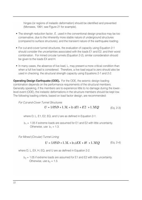
Operating <strong>Design</strong> Earthquake (ODE). For the ODE, the seismic design loading<br />
combination depends on the performance requirements <strong>of</strong> the structural members.<br />
Generally speaking, if the members are to experience little to no damage during the lowerlevel<br />
event (ODE), the inelastic deformations in the structure members should be kept low.<br />
The following loading criteria, based on load factor design, are recommended:<br />
For Cut-and-Cover Tunnel Structures<br />
Ê<br />
ˆ<br />
U = 1. 05 D +1.3L +b1ËE1 + E2 ¯ +1.3EQ<br />
(Eq. 2-3)<br />
where D, L, E1, E2, EQ, and U are as defined in Equation 2-1.<br />
b 1 = 1.05 if extreme loads are assumed for E1 and E2 with little uncertainty.<br />
Otherwise, use b 1 = 1.3.<br />
For Mined (Circular) Tunnel Lining<br />
Ê<br />
ˆ<br />
U = 1. 05 D +1.3L +b 2 ËEX + H ¯ +1.3EQ<br />
(Eq. 2-4)<br />
where D, L, EX, H, EQ, and U are as defined in Equation 2-2.<br />
b 2 = 1.05 if extreme loads are assumed for E1 and E2 with little uncertainty.<br />
Otherwise, use b 2 = 1.3.<br />
22


