Seismic Design of Tunnels - Parsons Brinckerhoff
Seismic Design of Tunnels - Parsons Brinckerhoff
Seismic Design of Tunnels - Parsons Brinckerhoff

You also want an ePaper? Increase the reach of your titles
YUMPU automatically turns print PDFs into web optimized ePapers that Google loves.
As Figures 28A and 28B show, earthquake motions <strong>of</strong> these two types have very<br />
different frequency characteristics, with the “N.E. EQ” motions displaying significantly<br />
increased high frequency components. The purpose <strong>of</strong> using two sets <strong>of</strong> design response<br />
spectra instead <strong>of</strong> one was to evaluate the effect <strong>of</strong> ground motion characteristics on<br />
soil/structure interaction.<br />
Note that these design spectra were developed for motions expected at rock outcrop<br />
(ground surface). For motions to be used as rigid base input in the FLUSH analysis, a<br />
suitable modification <strong>of</strong> ground motion characteristics should be made. This was achieved<br />
in this study by using the one-dimensional site response analysis program SHAKE based on<br />
wave propagation theory. Details <strong>of</strong> this de-convolution process can be found in Schnabel,<br />
et al.(1972).<br />
Flexibility Ratio for Rectangular <strong>Tunnels</strong><br />
Figure 30 shows the five different types <strong>of</strong> structure configurations that were analyzed.<br />
Note that although the configurations were limited to five types, the racking stiffness <strong>of</strong> each<br />
structure type was varied further (for parametric studies) by varying the properties <strong>of</strong> the<br />
structure members (e.g., EI and EA values). Similarly, the stiffness <strong>of</strong> the surrounding soil,<br />
as represented by shear modulus, was also varied in such a manner that the resulting<br />
relative stiffness between the soil medium and the structure covered a range that was <strong>of</strong><br />
interest. This relative stiffness, as represented by the Flexibility Ratio, F, will be defined in<br />
detail in the following paragraphs.<br />
The flexibility ratio for a rectangular tunnel, just as for a circular tunnel, is a measure <strong>of</strong><br />
the flexural stiffness <strong>of</strong> the medium relative to that <strong>of</strong> the tunnel structure. Under a seismic<br />
simple shear condition, this relative stiffness may be translated into the shear stiffness <strong>of</strong> the<br />
medium relative to the lateral racking stiffness <strong>of</strong> the rectangular frame structure.<br />
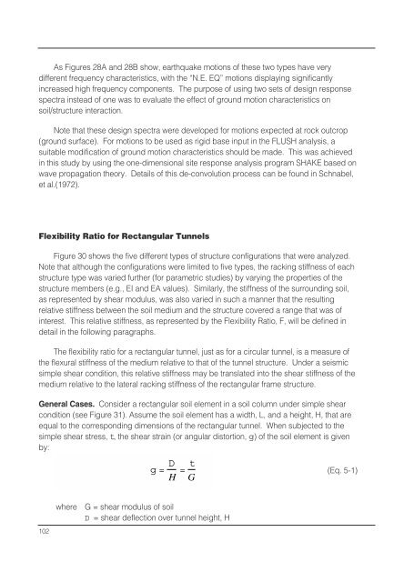
General Cases. Consider a rectangular soil element in a soil column under simple shear<br />
condition (see Figure 31). Assume the soil element has a width, L, and a height, H, that are<br />
equal to the corresponding dimensions <strong>of</strong> the rectangular tunnel. When subjected to the<br />
simple shear stress, t, the shear strain (or angular distortion, g) <strong>of</strong> the soil element is given<br />
by:<br />
g= D H = t G<br />
(Eq. 5-1)<br />
102<br />
where<br />
G = shear modulus <strong>of</strong> soil<br />
D = shear deflection over tunnel height, H