Seismic Design of Tunnels - Parsons Brinckerhoff
Seismic Design of Tunnels - Parsons Brinckerhoff
Seismic Design of Tunnels - Parsons Brinckerhoff

Create successful ePaper yourself
Turn your PDF publications into a flip-book with our unique Google optimized e-Paper software.
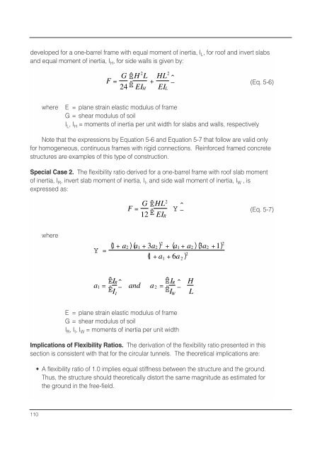
developed for a one-barrel frame with equal moment <strong>of</strong> inertia, I L , for ro<strong>of</strong> and invert slabs<br />
and equal moment <strong>of</strong> inertia, I H , for side walls is given by:<br />
F = G ÊH 2 L<br />
24 Ë EI H<br />
+ HL2<br />
EI L<br />
ˆ<br />
¯<br />
(Eq. 5-6)<br />
where<br />
E = plane strain elastic modulus <strong>of</strong> frame<br />
G = shear modulus <strong>of</strong> soil<br />
I L , I H = moments <strong>of</strong> inertia per unit width for slabs and walls, respectively<br />
Note that the expressions by Equation 5-6 and Equation 5-7 that follow are valid only<br />
for homogeneous, continuous frames with rigid connections. Reinforced framed concrete<br />
structures are examples <strong>of</strong> this type <strong>of</strong> construction.<br />
Special Case 2. The flexibility ratio derived for a one-barrel frame with ro<strong>of</strong> slab moment<br />
<strong>of</strong> inertia, I R , invert slab moment <strong>of</strong> inertia, I I , and side wall moment <strong>of</strong> inertia, I W , is<br />
expressed as:<br />
F = G ÊHL 2<br />
12 Ë EI R<br />
Y<br />
ˆ<br />
¯<br />
(Eq. 5-7)<br />
where<br />
( 1+ a2)a1 + 3a2<br />
Y= ( )2 + ( a 1+ a 2 )3a ( 2 +1) 2<br />
( 1 + a 1 + 6a 2 ) 2<br />
Ê<br />
a 1 =<br />
IR<br />
Ë ˆ¯ and a Ê<br />
2 = IR<br />
Ë<br />
ˆ¯<br />
I I<br />
I W<br />
H<br />
L<br />
E = plane strain elastic modulus <strong>of</strong> frame<br />
G = shear modulus <strong>of</strong> soil<br />
I R , I I , I W = moments <strong>of</strong> inertia per unit width<br />
Implications <strong>of</strong> Flexibility Ratios. The derivation <strong>of</strong> the flexibility ratio presented in this<br />
section is consistent with that for the circular tunnels. The theoretical implications are:<br />
• A flexibility ratio <strong>of</strong> 1.0 implies equal stiffness between the structure and the ground.<br />
Thus, the structure should theoretically distort the same magnitude as estimated for<br />
the ground in the free-field.<br />
110