Seismic Design of Tunnels - Parsons Brinckerhoff
Seismic Design of Tunnels - Parsons Brinckerhoff
Seismic Design of Tunnels - Parsons Brinckerhoff

You also want an ePaper? Increase the reach of your titles
YUMPU automatically turns print PDFs into web optimized ePapers that Google loves.
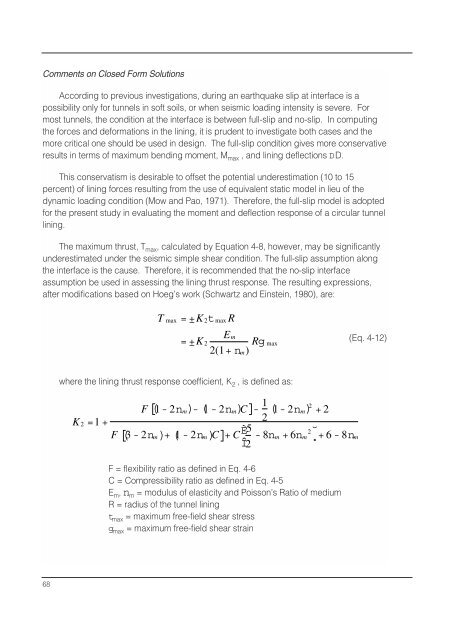
Comments on Closed Form Solutions<br />
According to previous investigations, during an earthquake slip at interface is a<br />
possibility only for tunnels in s<strong>of</strong>t soils, or when seismic loading intensity is severe. For<br />
most tunnels, the condition at the interface is between full-slip and no-slip. In computing<br />
the forces and deformations in the lining, it is prudent to investigate both cases and the<br />
more critical one should be used in design. The full-slip condition gives more conservative<br />
results in terms <strong>of</strong> maximum bending moment, M max , and lining deflections DD.<br />
This conservatism is desirable to <strong>of</strong>fset the potential underestimation (10 to 15<br />
percent) <strong>of</strong> lining forces resulting from the use <strong>of</strong> equivalent static model in lieu <strong>of</strong> the<br />
dynamic loading condition (Mow and Pao, 1971). Therefore, the full-slip model is adopted<br />
for the present study in evaluating the moment and deflection response <strong>of</strong> a circular tunnel<br />
lining.<br />
The maximum thrust, T max , calculated by Equation 4-8, however, may be significantly<br />
underestimated under the seismic simple shear condition. The full-slip assumption along<br />
the interface is the cause. Therefore, it is recommended that the no-slip interface<br />
assumption be used in assessing the lining thrust response. The resulting expressions,<br />
after modifications based on Hoeg’s work (Schwartz and Einstein, 1980), are:<br />
T max =±K 2 t max R<br />
E m<br />
=±K 2<br />
2(1+n m )<br />
Rg max<br />
(Eq. 4-12)<br />
where the lining thrust response coefficient, K 2 , is defined as:<br />
F[ ( 1- 2n m )- ( 1 - 2n m )C ]- 1 (<br />
K 2 =1 +<br />
2 1- 2n m) 2 + 2<br />
F[ ( 3 - 2n m )+ ( 1 - 2n m )C ]+ C È5 2<br />
- 8nm +<br />
˘<br />
6nm<br />
Î2 ˚+ 6 - 8nm<br />
F = flexibility ratio as defined in Eq. 4-6<br />
C = Compressibility ratio as defined in Eq. 4-5<br />
E m , n m = modulus <strong>of</strong> elasticity and Poisson’s Ratio <strong>of</strong> medium<br />
R = radius <strong>of</strong> the tunnel lining<br />
t max = maximum free-field shear stress<br />
g max = maximum free-field shear strain<br />
68