Seismic Design of Tunnels - Parsons Brinckerhoff
Seismic Design of Tunnels - Parsons Brinckerhoff
Seismic Design of Tunnels - Parsons Brinckerhoff
Create successful ePaper yourself
Turn your PDF publications into a flip-book with our unique Google optimized e-Paper software.
4.3 Lining Conforming to Free-Field Shear Deformations<br />
When a circular lining is assumed to oval in accordance with the deformations<br />
imposed by the surrounding ground (e.g., shear), the lining’s transverse sectional stiffness<br />
is completely ignored. This assumption is probably reasonable for most circular tunnels in<br />
rock and in stiff soils, because the lining stiffness against distortion is low compared with<br />
that <strong>of</strong> the surrounding medium. Depending on the definition <strong>of</strong> “ground deformation <strong>of</strong><br />
surrounding medium,” however, a design based on this assumption may be overly<br />
conservative in some cases and non-conservative in others. This will be discussed further<br />
as follows.<br />
Shear distortion <strong>of</strong> the surrounding ground, for this discussion, can be defined in two<br />
ways. If the non-perforated ground in the free-field is used to derive the shear distortion<br />
surrounding the tunnel lining, the lining is to be designed to conform to the maximum<br />
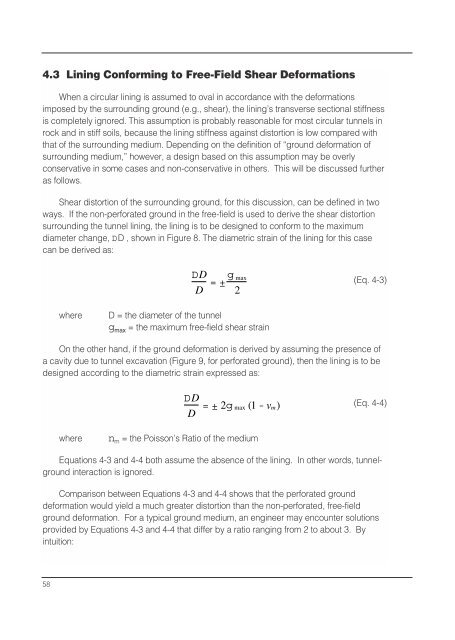
diameter change, DD , shown in Figure 8. The diametric strain <strong>of</strong> the lining for this case<br />
can be derived as:<br />
DD<br />
D =±g max<br />
2<br />
(Eq. 4-3)<br />
where<br />
D = the diameter <strong>of</strong> the tunnel<br />
g max = the maximum free-field shear strain<br />
On the other hand, if the ground deformation is derived by assuming the presence <strong>of</strong><br />
a cavity due to tunnel excavation (Figure 9, for perforated ground), then the lining is to be<br />
designed according to the diametric strain expressed as:<br />
DD<br />
D<br />
=±2g max (1 - vm)<br />
(Eq. 4-4)<br />
where<br />
n m = the Poisson’s Ratio <strong>of</strong> the medium<br />
Equations 4-3 and 4-4 both assume the absence <strong>of</strong> the lining. In other words, tunnelground<br />
interaction is ignored.<br />
Comparison between Equations 4-3 and 4-4 shows that the perforated ground<br />
deformation would yield a much greater distortion than the non-perforated, free-field<br />
ground deformation. For a typical ground medium, an engineer may encounter solutions<br />
provided by Equations 4-3 and 4-4 that differ by a ratio ranging from 2 to about 3. By<br />
intuition:<br />
58


