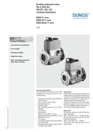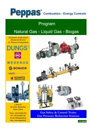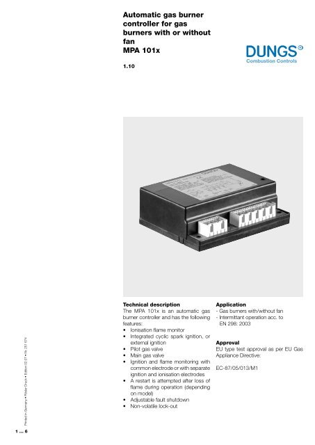
Automatic gas burner controller for gas burners with or without fan ...
Automatic gas burner controller for gas burners with or without fan ...
Automatic gas burner controller for gas burners with or without fan ...

You also want an ePaper? Increase the reach of your titles
YUMPU automatically turns print PDFs into web optimized ePapers that Google loves.
<strong>Automatic</strong> <strong>gas</strong> <strong>burner</strong><br />
<strong>controller</strong> <strong>f<strong>or</strong></strong> <strong>gas</strong><br />
<strong>burner</strong>s <strong>with</strong> <strong>or</strong> <strong>with</strong>out<br />
<strong>fan</strong><br />
MPA 101x<br />
1.10<br />
Printed in Germany • Rösler Druck • Edition 02.07 • Nr. 251 674<br />
… 6<br />
Technical description<br />
The MPA 101x is an automatic <strong>gas</strong><br />
<strong>burner</strong> <strong>controller</strong> and has the following<br />
features:<br />
• Ionisation flame monit<strong>or</strong><br />
• Integrated cyclic spark ignition, <strong>or</strong><br />
external ignition<br />
• Pilot <strong>gas</strong> valve<br />
• Main <strong>gas</strong> valve<br />
• Ignition and flame monit<strong>or</strong>ing <strong>with</strong><br />
common electrode <strong>or</strong> <strong>with</strong> separate<br />
ignition and ionisation electrodes<br />
• A restart is attempted after loss of<br />
flame during operation (depending<br />
on model)<br />
• Adjustable fault shutdown<br />
• Non-volatile lock-out<br />
Application<br />
- Gas <strong>burner</strong>s <strong>with</strong>/<strong>with</strong>out <strong>fan</strong><br />
- Intermittant operation acc. to<br />
EN 298: 2003<br />
Approval<br />
EU type test approval as per EU Gas<br />
Appliance Directive:<br />
EC-87/05/013/M1
<strong>Automatic</strong> <strong>gas</strong> <strong>burner</strong> <strong>controller</strong><br />
MPA 101x<br />
The MPA 101x is installed in a plastic<br />
housing <strong>with</strong> RAST5 terminals.<br />
Assembled on a single PCB, the<br />
automatic <strong>gas</strong> <strong>burner</strong> <strong>controller</strong> uses<br />
electronic timers, which ensures exact<br />
operating times, even in the case<br />
of extreme voltage and temperature<br />
fluctuation <strong>or</strong> very sh<strong>or</strong>t operating<br />
cycles.<br />
The MPA 101x comprises:<br />
- the program control module,<br />
- the flame monit<strong>or</strong> which operates<br />
acc<strong>or</strong>ding to the ionisation<br />
principle,<br />
- the ignition electronics and the<br />
integrated ignition coil (depending<br />
on model).<br />
Models <strong>with</strong>out air monit<strong>or</strong>: When<br />
the <strong>controller</strong> signals that heat is required,<br />
the ignition is activated after<br />
a start-up delay period and the pilot<br />
<strong>gas</strong> solenoid valve is opened.<br />
Models <strong>with</strong> air monit<strong>or</strong>: The MPA 101x<br />
waits until the contact of the air pressure<br />
monit<strong>or</strong> is open. Then the blower is<br />
switched on, the system waits until the<br />
air pressure monit<strong>or</strong> responds.<br />
At the end of the pre-purge time, the<br />
ignition is started and the pilot <strong>gas</strong> valve<br />
is opened.<br />
The ignition is switched off when the pilot<br />
flame signal is generated. At the end of<br />
the ignition safety time (SZA), the main <strong>gas</strong><br />
valve is opened if the flame is lit.<br />
If a flame is not <strong>f<strong>or</strong></strong>med during the ignition<br />
safety time, depending on the model<br />
- up to 4 restart attemps<br />
- a complete recycling<br />
<strong>or</strong><br />
- the control interlocks in the fault stage<br />
If a loss of flame occurs during operation,<br />
all <strong>gas</strong> solenoid valves are switched off<br />
during the extinction safety time (SZB).<br />
The MPA 101x is then interlocked in the<br />
fault state, <strong>or</strong> an attempt to restart the<br />
<strong>burner</strong> is made.<br />
In the case of a n<strong>or</strong>mal shut-down, the<br />
<strong>gas</strong> valves are closed. If the flame signal<br />
is simulated be<strong>f<strong>or</strong></strong>e fuel feed is enabled,<br />
start-up is disabled <strong>f<strong>or</strong></strong> as long as the<br />
flame signal is applied.<br />
Fault unlock<br />
The MPA 101x Mod. ..L must be unlocked<br />
via an external contact.<br />
MPA 101x Mod. ..V-models <strong>with</strong> adjustable<br />
fault unlocking device can be<br />
unlocked by shutting down the heat requirement<br />
<strong>or</strong> <strong>with</strong> an external contact.<br />
Order date<br />
Type<br />
MPA 1012<br />
Mod. 5.1.0 TCL<br />
MPA 1015<br />
Mod. 5.1.30 TCL<br />
Order no<br />
Specifications-No.<br />
Classification<br />
as per<br />
EN 298<br />
Fan<br />
Air<br />
monit<strong>or</strong>ing<br />
Start up<br />
delay<br />
period<br />
Prepuring<br />
time<br />
250 867 54110120 ATCLXN<br />
- -<br />
5 s -<br />
250 868 54110060 FTCLXN<br />
• • -<br />
30 s<br />
… 6
AWZ Start-up delay period<br />
BF Blower mot<strong>or</strong><br />
F Flame<br />
PS Air pressure switch<br />
R Controller<br />
AL Fault indication<br />
STVZ Fault interlock time<br />
SZA Ignition safety time<br />
SZB Extinction safety time<br />
VSZ Pre-purge time<br />
Y1 Pilot <strong>gas</strong> valve<br />
Y2 Main <strong>gas</strong> valve<br />
Z Ignition<br />
Program flow <strong>f<strong>or</strong></strong> models <strong>with</strong>out<br />
air monit<strong>or</strong>ing<br />
Startup <strong>with</strong> flame <strong>f<strong>or</strong></strong>mation<br />
AWZ VGZ<br />
Startup <strong>with</strong>out flame <strong>f<strong>or</strong></strong>mation<br />
AWZ VGZ<br />
SZA<br />
SZA<br />
STVZ<br />
Flame failure <strong>with</strong>out recycling (Mod. TLL)<br />
SZB<br />
STVZ<br />
Flame failure <strong>with</strong> recycling (Mod. TCL)<br />
SZB<br />
AWZ<br />
VGZ<br />
SZA<br />
R<br />
Z<br />
Y1<br />
F<br />
Y2<br />
AL<br />
R<br />
Z<br />
Y1<br />
F<br />
Y2<br />
AL<br />
R<br />
Z<br />
Y1<br />
F<br />
Y2<br />
AL<br />
R<br />
Z<br />
Y1<br />
F<br />
Y2<br />
AL<br />
Program flow <strong>f<strong>or</strong></strong> models <strong>with</strong><br />
air monit<strong>or</strong>ing<br />
Startup <strong>with</strong> flame <strong>f<strong>or</strong></strong>mation<br />
VSZ<br />
VGZ<br />
SZA<br />
Startup <strong>with</strong>out flame <strong>f<strong>or</strong></strong>mation<br />
VSZ<br />
VGZ<br />
SZA<br />
STVZ<br />
Startup <strong>with</strong>out flame <strong>f<strong>or</strong></strong>mation (Mod. TLL)<br />
SZB<br />
STVZ<br />
Startup <strong>with</strong> flame <strong>f<strong>or</strong></strong>mation (Mod. TCL)<br />
SZB<br />
VSZ<br />
VGZ<br />
SZA<br />
R<br />
BF<br />
PS<br />
Z<br />
Y1<br />
F<br />
Y2<br />
AL<br />
R<br />
BF<br />
PS<br />
Z<br />
Y1<br />
F<br />
Y2<br />
AL<br />
R<br />
BF<br />
PS<br />
Z<br />
Y1<br />
F<br />
Y2<br />
AL<br />
R<br />
BF<br />
PS<br />
Z<br />
Y1<br />
F<br />
Y2<br />
AL<br />
Prepurge time<br />
after flame<br />
failure<br />
Ignition<br />
Attempts<br />
Safety time<br />
Start up Operating<br />
Restart<br />
External<br />
ignition<br />
RAST 5<br />
connect<strong>or</strong><br />
set<br />
- 3 5 s 1 s<br />
•<br />
_ 226 936<br />
20 s 3 5 s 1 s<br />
•<br />
- 226 934<br />
… 6
Measuring instrument connection<br />
<strong>f<strong>or</strong></strong> models <strong>with</strong> integrated<br />
ignition (single probe)<br />
<br />
<br />
<br />
<br />
<br />
<br />
<br />
<br />
<br />
<br />
Ionisation flame monit<strong>or</strong>ing<br />
An ionisation electrode serves as a<br />
flame probe, and the <strong>burner</strong> head usually<br />
serves as the earth. Pay attention<br />
to good flame contact at the <strong>burner</strong><br />
head.<br />
The <strong>burner</strong> head must be securely connected<br />
to PE to feed back the ionisation<br />
current.<br />
The insulation resistance of the ionisation<br />
electrode should exceed 50 MΩ.<br />
- Switch off <strong>controller</strong>s, monit<strong>or</strong>ing<br />
devices and limiters (if any)<br />
- Switching points of <strong>gas</strong> pressure<br />
switch (if any)<br />
- Disconnect flame monit<strong>or</strong> and ionisation<br />
line <strong>or</strong> sh<strong>or</strong>t-circuit the electrode<br />
to earth.<br />
Fuses<br />
Protect the automatic <strong>gas</strong> <strong>burner</strong> <strong>controller</strong><br />
externally using a 6.3A slow-blow<br />
back-up fuse <strong>or</strong> a 10A quick-acting<br />
fuse. Pay attention to the permissible<br />
switching capacities.<br />
1) cf. Measuring the ionisation current<br />
Measuring instrument connection<br />
<strong>f<strong>or</strong></strong> models <strong>with</strong> integrated<br />
ignition (dual probe)<br />
<br />
<br />
<br />
<br />
<br />
<br />
2) cf.Ionisation flame monit<strong>or</strong>ing<br />
Measuring instrument connection<br />
<strong>f<strong>or</strong></strong> models <strong>with</strong> external<br />
ignition<br />
<br />
<br />
Measuring the ionisation current<br />
The intensity of the ionisation current can<br />
be measured <strong>with</strong> a DC current microammeter.<br />
The current intensity should<br />
not be less than 3 µA in operation. A fault<br />
cut-off occurs if the ionisation current<br />
drops below approx. 1 µA.<br />
To measure the ionisation current, connect<br />
the micro-ammeter between the<br />
ionisation electrode and the connect<strong>or</strong><br />
(see drawing <strong>f<strong>or</strong></strong> connection of the<br />
measuring instrument).<br />
Installation<br />
The automatic <strong>gas</strong> <strong>burner</strong> <strong>controller</strong> can<br />
be installed in any position.<br />
Connection to power supply<br />
Use RAST5 connect<strong>or</strong>s to connect<br />
the <strong>burner</strong> to the power supply (see<br />
specifications). Wiring must be carried<br />
out in compliance <strong>with</strong> the prevailing<br />
local regulations and as shown in the<br />
wiring diagram.<br />
If a fuse is faulty, the safety<br />
of the automatic <strong>gas</strong> <strong>burner</strong><br />
<strong>controller</strong> must be checked, as<br />
there is a risk of contact welding<br />
due to a sh<strong>or</strong>t circuit.<br />
The effects of leak search<br />
spray and similar substances<br />
may cause dangerous<br />
flame-simulating conditions on<br />
ionisation electrodes and conduct<strong>or</strong>s,<br />
e.g. ionisation ammeters.<br />
There<strong>f<strong>or</strong></strong>e please handle<br />
leak search sprays and similar<br />
substances <strong>with</strong> extreme care<br />
so that they are only applied<br />
to the leak test points. If it is<br />
not possible to limit the use of<br />
these substances, ionisation<br />
electrodes and conduct<strong>or</strong>s<br />
must be protected be<strong>f<strong>or</strong></strong>e applying<br />
the substances. It is not<br />
sufficient to merely wipe off the<br />
leak search spray substance<br />
after application.<br />
<br />
<br />
<br />
<br />
<br />
<br />
<br />
Commissioning<br />
Be<strong>f<strong>or</strong></strong>e starting up the <strong>burner</strong> <strong>controller</strong>,<br />
check that all terminals are properly<br />
connected. When commissioning the<br />
<strong>controller</strong>, check the following safety<br />
functions:<br />
Ign<strong>or</strong>ing the installation<br />
and operating instructions<br />
may result in injury to<br />
life and limb <strong>or</strong> damage to<br />
property. Compliance <strong>with</strong><br />
the applicable instructions is<br />
there<strong>f<strong>or</strong></strong>e imperative. Unauth<strong>or</strong>ised<br />
tampering <strong>with</strong> the<br />
electronics will render the<br />
warranty <strong>f<strong>or</strong></strong> this equipment<br />
null and void.<br />
… 6
Terminal diagram <strong>f<strong>or</strong></strong> models <strong>with</strong> integrated ignition, single probe<br />
<br />
<br />
<br />
<br />
<br />
<br />
<br />
<br />
<br />
<br />
<br />
<br />
<br />
<br />
<br />
<br />
<br />
<br />
<br />
<br />
<br />
<br />
<br />
<br />
<br />
Terminal diagram <strong>f<strong>or</strong></strong> models <strong>with</strong> integrated ignition, dual probe<br />
<br />
<br />
<br />
<br />
<br />
<br />
<br />
<br />
<br />
<br />
<br />
<br />
<br />
<br />
<br />
<br />
<br />
<br />
<br />
<br />
<br />
Terminal diagram <strong>f<strong>or</strong></strong> models <strong>with</strong> external ignition<br />
<br />
<br />
<br />
<br />
<br />
<br />
<br />
<br />
<br />
<br />
<br />
<br />
<br />
<br />
<br />
<br />
<br />
<br />
<br />
<br />
AL<br />
BF<br />
F1<br />
IE<br />
External fault indication<br />
Blower mot<strong>or</strong><br />
Back-up fuse, max. 6.3 A, slow-blow<br />
Ionisation electrode<br />
IT Ignition trans<strong>f<strong>or</strong></strong>mer<br />
IZE Ionisation and ignition electrode<br />
PS Air pressure switch<br />
R Controller<br />
RS Remote unlock<br />
X1...X3<br />
Y1<br />
Y2<br />
ZE<br />
Terminal designation<br />
Pilot <strong>gas</strong> solenoid valve<br />
Main <strong>gas</strong> valve<br />
Ignition electrode<br />
… 6
<strong>Automatic</strong> <strong>gas</strong> <strong>burner</strong> <strong>controller</strong> <strong>f<strong>or</strong></strong><br />
<strong>gas</strong> <strong>burner</strong>s <strong>with</strong> and <strong>with</strong>out <strong>fan</strong><br />
MPA 101x<br />
Dimensions<br />
<br />
<br />
<br />
<br />
<br />
<br />
<br />
<br />
MPA 101x Table of connect<strong>or</strong>s<br />
Function<br />
Slot No. No.of Code Conpoles<br />
nect<strong>or</strong> No.<br />
Pilot <strong>gas</strong> valve Y1 02 ... 1) 02 K51<br />
Main <strong>gas</strong> valve Y2 02 ... 1) 02 K53<br />
Blower mot<strong>or</strong> BF 02 … 1) 02 K49<br />
Power supply IN 02 … 1) 02 K51<br />
Ion. measuring connection IE 02 … 1) 02 K50<br />
Air pressure switch PS 02 … 1) 02 K12<br />
High-voltage con- X3 01 Fast-On<br />
nection<br />
2,8 x 0,8 mm<br />
External fault display/ ST 03 … 1) 03 K66<br />
unlock<br />
Ignition trans<strong>f<strong>or</strong></strong>mer IT 02 … 1) 02 K44<br />
<br />
<br />
<br />
Specifications<br />
Nominal voltage ~(AC) 230 V -15% +10 %<br />
Frequency<br />
50 Hz<br />
Power consumption approx. 5 VA<br />
Internal strip conduct<strong>or</strong> fuse 2A, non-interchangeable<br />
Back-up fuse<br />
max. 6,3 A slow-blow/<br />
10 A quick-acting<br />
Switching capacities:<br />
Ignition<br />
Ignition <strong>gas</strong> valve<br />
Main <strong>gas</strong> valve<br />
Overall switching capacity<br />
Blower mot<strong>or</strong><br />
Flame monit<strong>or</strong><br />
Ionisation current/operation > 3 µA<br />
Switch-off sensitivity < 1 µA<br />
230 VAC/1 A (only <strong>f<strong>or</strong></strong> models<br />
<strong>with</strong> external ignition)<br />
230 VAC/1 A<br />
230 VAC/1 A<br />
max. 2 A<br />
230 VAC/2 A<br />
ionisation<br />
Models <strong>with</strong> integrated ignition<br />
Ignition<br />
cycle sparks<br />
Ignition voltage<br />
approx. 20 kV<br />
Ignition frequency<br />
approx. 15 Hz<br />
Distance between electrodes 3 mm to 4 mm<br />
Ignition wire length<br />
max. 1 m<br />
Fault remote unlock Remote unlock<br />
Degree of protection IP 20 - IP 40 must be<br />
ensured by installation<br />
Ambient temperature 0 °C to 60 °C<br />
Connection<br />
RAST5, encoded<br />
PE connection<br />
separate<br />
Weight<br />
0.35 kg<br />
1) Lumberg: Insulation displaceement terminal 3623…/<br />
screw-type terminal 3611…<br />
We reserve the right to make any changes in the interest of technical progress.<br />
Head Offices and Fact<strong>or</strong>y<br />
Karl Dungs GmbH & Co. KG<br />
Siemensstraße 6-10<br />
D-73660 Urbach, Germany<br />
Telephone +49 (0)7181-804-0<br />
Fax +49 (0)7181-804-166<br />
Postal address<br />
Karl Dungs GmbH & Co. KG<br />
Postfach 12 29<br />
D-73602 Sch<strong>or</strong>nd<strong>or</strong>f, Germany<br />
e-mail info@dungs.com<br />
Internet www.dungs.com<br />
… 6