GasBloc Solenoid valve Single or multiple actuator GB 053 D02
GasBloc Solenoid valve Single or multiple actuator GB 053 D02
GasBloc Solenoid valve Single or multiple actuator GB 053 D02

You also want an ePaper? Increase the reach of your titles
YUMPU automatically turns print PDFs into web optimized ePapers that Google loves.
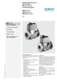
<strong>GasBloc</strong><br />
<strong>Solenoid</strong> <strong>valve</strong><br />
<strong>Single</strong> <strong>or</strong> <strong>multiple</strong> actuat<strong>or</strong><br />
<strong>GB</strong> <strong>053</strong> <strong>D02</strong><br />
3.21<br />
Printed in Germany • Rösler Druck • Edition 02.08 • Nr. 250 942<br />
1 … 6<br />
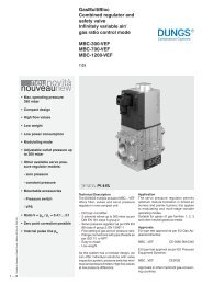
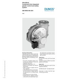
Technical description<br />
The <strong>GB</strong> <strong>053</strong> gas <strong>valve</strong> family comprises<br />
1, 2 <strong>or</strong> 3 solenoid <strong>valve</strong>s as single <strong>or</strong><br />
<strong>multiple</strong> actuat<strong>or</strong>s.<br />
Safety combinations f<strong>or</strong> one- <strong>or</strong> two-stage<br />
operating modes in compact size:<br />
• <strong>Solenoid</strong> <strong>valve</strong>s up to 65 mbar as<br />
per EN161 Class B, Group 2.<br />
• Fast-opening, fast-closing solenoid<br />
<strong>valve</strong>s.<br />
• High flow rate with low pressure<br />
losses.<br />
• Multiple actuat<strong>or</strong> comprising 3 solenoid<br />
<strong>valve</strong>s in two-stage <strong>or</strong> modulating<br />
design.<br />
• <strong>Single</strong> actuat<strong>or</strong> also in right angle<br />
design.<br />
• Multiple actuat<strong>or</strong>s with pilot gas<br />
flow and flow restriction screw f<strong>or</strong><br />
restricted gas flow and main gas flow<br />
depending on version.<br />
• Compact size, low weight.<br />
Application<br />
Suitable f<strong>or</strong> gas single room heaters<br />
and gas-consuming equipment with<br />
burners not requiring a pressure regulat<strong>or</strong>.<br />
Suitable f<strong>or</strong> gases of gas families<br />
1, 2 and 3 and other neutral gaseous<br />
media.<br />
Approvals<br />
EC type test approval as per EC Gas<br />
Appliance Directive.<br />
<strong>GB</strong> <strong>053</strong> CE-0085 AS 0847<br />
Approvals in other imp<strong>or</strong>tant gasconsuming<br />
countries.
Combinations<br />
Multifunctional gas control <strong>valve</strong> <strong>GB</strong> <strong>053</strong> <strong>D02</strong><br />
Specification<br />
Main types<br />
Pressure relief <strong>valve</strong><br />
Angle design<br />
Double solenoid <strong>valve</strong><br />
Two-stage operation<br />
Modulating operation<br />
<strong>GB</strong> <strong>053</strong> D12 B -- -- -- -- -- -- -- -- -- --<br />
minimum modulat<strong>or</strong><br />
current [mA]<br />
maximum modulat<strong>or</strong><br />
current [mA]<br />
Start gas connection<br />
Main gas flow control<br />
<strong>valve</strong><br />
<strong>GB</strong> <strong>053</strong> D22 B -- -- -- -- -- -- -- --<br />
<strong>GB</strong> <strong>053</strong> <strong>D02</strong> B -- -- -- -- -- --<br />
<strong>GB</strong>-(Z) <strong>053</strong> <strong>D02</strong> B -- -- -- --<br />
<strong>GB</strong>-(M) <strong>053</strong> <strong>D02</strong> B -- -- 50 165<br />
Reduced gas<br />
flow control <strong>valve</strong><br />
Pressure tapping<br />
Filter<br />
MPA 101x<br />
standard optional not available<br />
Type key of <strong>GasBloc</strong><br />
<strong>GB</strong>- XXXXX XXX DXX SXX<br />
Control of V1 and V2<br />
0 = common<br />
2 = separated<br />
Outlet pressure Inlet pressure<br />
0 = 0 mbar bis 65 mbar<br />
2 = 1,5 - 20 mbar bis 65 mbar<br />
4 = 3 - 40 mbar bis 65 mbar<br />
S = Series (type-independent)<br />
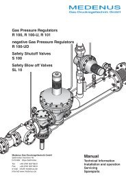
Operating mode IV: <strong>GB</strong>-(Z) <strong>053</strong> <strong>D02</strong><br />
Double <strong>valve</strong> with additional two-stage<br />
drive. Start gas after opening V1.<br />
Reduced gas flow is released by<br />
opening V2. Main gas flow after opening<br />
Z (6). Main and reduced gas flows can<br />
be set via control <strong>valve</strong> screws.<br />
Description of main components<br />
<strong>Solenoid</strong> <strong>valve</strong>s<br />
<strong>Solenoid</strong> <strong>valve</strong>s as per EN 161, Class<br />
B. DC coils are protected against voltage<br />
transients.<br />
Dirt trap device<br />
Fine-meshed strainer to protect fitting.<br />
Pilot gas<br />
Pilot gas connection between V1 and V2.<br />
Pressure instrument glands<br />
On inlet and outlet sides<br />
Main flow control <strong>valve</strong><br />
Control <strong>valve</strong> screw (3) f<strong>or</strong> adjusting<br />
the main gas flow.<br />
Reduced flow control <strong>valve</strong><br />
Control <strong>valve</strong> screw f<strong>or</strong> setting the<br />
Gas train schematic diagram<br />
1 = two class B solenoid <strong>valve</strong>s with pressure regulat<strong>or</strong><br />
2 = two class B solenoid <strong>valve</strong>s without pressure regulat<strong>or</strong><br />
Valve design<br />
0 = Double <strong>valve</strong><br />
1 = <strong>Single</strong> <strong>valve</strong>, right angle<br />
2 = <strong>Single</strong> <strong>valve</strong>, straight<br />
Design type (generation) D<br />
Construction size, nominal diameter<br />
05 = p max. = 65 mbar<br />
3 = Rp 1/4<br />
5 = Rp 1/2<br />
7 = Rp 3/4<br />
Opening behaviour + main volume restrict<strong>or</strong><br />
without = fast-opening, fast-closing<br />
-L = slow-opening<br />
-E = adjustable start gas<br />
-P = pilotgas connection<br />
-G = Gas/Air ratio<br />
-D = main flow setting<br />
-N = Zero-Govern<strong>or</strong><br />
-M = electrical modulating type<br />
-W = Whirlwind version<br />
-Z = two stage<br />
<strong>GasBloc</strong><br />
reduced gas flow. The reduced gas<br />
flow can be set to between 10% and<br />
80% of the main gas flow.<br />
<strong>Solenoid</strong> <strong>valve</strong> operating modes<br />
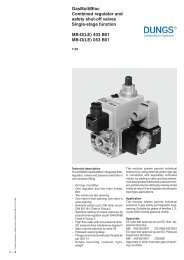
Operating mode I: <strong>GB</strong> <strong>053</strong> D12<br />
<strong>Single</strong> solenoid <strong>valve</strong> in angle<br />
design. Main gas flow is released<br />
by opening V1.<br />
<strong>Solenoid</strong> <strong>valve</strong> operating modes<br />
Operating mode II: <strong>GB</strong> <strong>053</strong> D22<br />
<strong>Single</strong> solenoid <strong>valve</strong> in straight<br />
design. Main gas flow is released<br />
by opening V1.<br />
Operating mode III: <strong>GB</strong> <strong>053</strong> <strong>D02</strong><br />
Double solenoid <strong>valve</strong>. Start gas after<br />
opening V1. Main gas flow is released<br />
by opening V2. Main gas flow can<br />
be set via control <strong>valve</strong> screw.<br />
Operating mode V: <strong>GB</strong>-(M) <strong>053</strong> <strong>D02</strong><br />
Double solenoid <strong>valve</strong> with additional<br />
modulating drive. Start gas after opening<br />
V1. Reduced gas flow is released<br />
by opening V2. To modulate to main<br />
gas flow, activate M (8). Main and<br />
reduced gas flows can be set via<br />
control <strong>valve</strong> screws.<br />
Operating and assembly<br />
instruction<br />
Always comply with operating and assembly<br />
instructions of <strong>GB</strong> <strong>053</strong>!<br />
Only technical qualified personel<br />
may w<strong>or</strong>k on the BM 740.<br />
Always comply with country-specific<br />
standards, and mounting and<br />
maintenance regulations.<br />
Never carry out w<strong>or</strong>k when device<br />
is subject to gas pressure <strong>or</strong> connected<br />
to power supply. No naked flames!<br />
Always comply with public regulations.<br />
During assembly and mounting<br />
w<strong>or</strong>k, ensures that no metal chips,<br />
dirt <strong>or</strong> other f<strong>or</strong>eign matter enter in<br />
to the control. Only use approved<br />
sealing compounds.<br />
On completion of w<strong>or</strong>k on <strong>GB</strong> <strong>053</strong>, carry<br />
out leakage and functional tests.<br />
2 … 6
Mounting dimensions [mm]<br />
Mode I<br />
<strong>GB</strong> <strong>053</strong> D12<br />
<br />
<br />
<br />
<br />
<br />
<br />
<br />
<br />
<br />
<br />
<br />
<br />
<br />
<br />
Mode II<br />
<strong>GB</strong> <strong>053</strong> D22<br />
<br />
<br />
<br />
<br />
<br />
V1<br />
Max<br />
<br />
<br />
<br />
OUT<br />
4 1<br />
2<br />
3<br />
4<br />
<br />
<br />
<br />
<br />
<br />
<br />
<br />
<br />
Mode III<br />
<strong>GB</strong> <strong>053</strong> <strong>D02</strong><br />
<br />
<br />
V1<br />
V2<br />
Max<br />
<br />
OUT<br />
4 1<br />
2<br />
2<br />
3<br />
4<br />
<br />
<br />
<br />
<br />
5<br />
<br />
<br />
<br />
<br />
<br />
<br />
<br />
<br />
3 … 6
Mounting dimensions [mm]<br />
Mode IV - two-stage<br />
<strong>GB</strong>-(Z) <strong>053</strong> <strong>D02</strong><br />
7<br />
3<br />
5<br />
4<br />
<br />
V1<br />
V2<br />
Z<br />
Max.<br />
<br />
OUT<br />
<br />
4 1<br />
2<br />
2<br />
6<br />
Min.<br />
3<br />
4<br />
<br />
<br />
7<br />
<br />
<br />
5<br />
<br />
<br />
<br />
<br />
<br />
<br />
<br />
<br />
Mounting dimensions [mm]<br />
Mode V - modulating<br />
<strong>GB</strong>-(M) <strong>053</strong> <strong>D02</strong><br />
5<br />
7<br />
3<br />
4<br />
<br />
V1<br />
V2<br />
Z<br />
Max.<br />
OUT<br />
4 1<br />
2<br />
2<br />
6<br />
Min.<br />
3<br />
4<br />
<br />
<br />
7<br />
5<br />
<br />
<br />
<br />
<br />
<br />
<br />
<br />
<br />
<br />
<br />
<br />
<br />
4 … 6
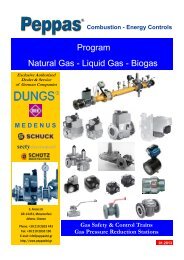
Flow diagram<br />
<br />
<br />
<br />
<br />
<br />
<br />
<br />
<br />
<br />
<br />
<br />
<br />
<br />
<br />
<br />
<br />
<br />
<br />
<br />
<br />
<br />
<br />
<br />
<br />
<br />
<br />
<br />
<br />
<br />
<br />
<br />
<br />
<br />
5 … 6
<strong>GasBloc</strong><br />
<strong>Solenoid</strong> <strong>valve</strong><br />
<strong>Single</strong> and <strong>multiple</strong> actuat<strong>or</strong><br />
<strong>GB</strong> <strong>053</strong><br />
Technical data Nominal width DN 8<br />
Gas connection1<br />
M14 x 1.5 f<strong>or</strong> tube dia. of 8 <strong>or</strong><br />
Rp 1/4 ISO 7/1<br />
Pilot gas connection<br />
M10 x 1 f<strong>or</strong> 6 mm dia., 4 mm dia <strong>or</strong><br />
<strong>GB</strong>-(P) <strong>053</strong> <strong>D02</strong><br />
1/4 tube<br />
Max. operating pressure<br />
65 mbar<br />
Nominal flow rate <strong>GB</strong> <strong>053</strong> <strong>D02</strong> Partial load (V1 + V2)<br />
Stage I at ∆p 3 mbar<br />
min. 30 l/h air<br />
max. 700 l/h air<br />
Main load (V1+V2+Z/M)<br />
Stage II at ∆p 3 mbar<br />
max. 830 l/h air<br />
Nominal flow rate <strong>GB</strong> <strong>053</strong> D12<br />
<strong>GB</strong> <strong>053</strong> D22<br />
at ∆p 3 mbar<br />
max. 1240 l/h air<br />
Ambient temperature -15 °C to +80 °C<br />
St<strong>or</strong>age temperature -25 °C to +80 °C<br />
<strong>Solenoid</strong> <strong>valve</strong>s 1 to 2 <strong>valve</strong>s to EN 161 Class B,<br />
Group 2<br />
Opening time<br />
< 1 s, fast opening<br />
Closing time<br />
< 1 s, fast closing<br />
Degree of protection IP 20 as per IEC 529 (EN 605299)<br />
Switch-on duration<br />
100 % on period<br />
Voltage DC: 24 V +10 % -15 %<br />
AC: 24 V, +10 % - 15 %, 50 - 60 Hz<br />
AC: 230 V, +10 % -15 %, 50 - 60 Hz<br />
Power consumption of coils<br />
5,5 VA per coil<br />
Power supply Flat connect<strong>or</strong> 6.3 x 0.8 as per DIN 46244<br />
Installation position<br />
Optimum equipment<br />
<strong>Solenoid</strong> at any position between<br />
vertical and h<strong>or</strong>izontal axis.<br />
Automatic burner control MPA 101x<br />
We reserve the right to make any changes in the interests of technical progress.<br />
Head Offices and Fact<strong>or</strong>y<br />
Karl Dungs GmbH & Co. KG<br />
Siemensstraße 6-10<br />
D-73660 Urbach, Germany<br />
Telephone +49 (0)7181-804-0<br />
Fax +49 (0)7181-804-166<br />
Postal address<br />
Karl Dungs GmbH & Co. KG<br />
Postfach 12 29<br />
D-73602 Sch<strong>or</strong>nd<strong>or</strong>f, Germany<br />
e-mail info@dungs.com<br />
Internet www.dungs.com<br />
6 … 6