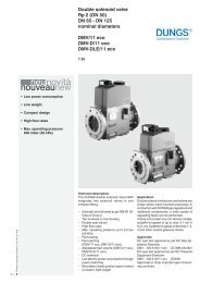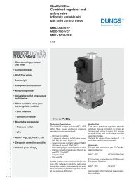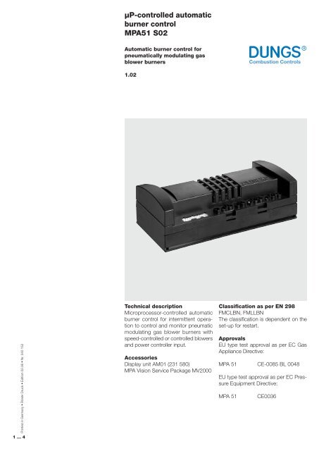
µP-controlled automatic burner control MPA51 S02 - Peppas Ltd ...
µP-controlled automatic burner control MPA51 S02 - Peppas Ltd ...
µP-controlled automatic burner control MPA51 S02 - Peppas Ltd ...

You also want an ePaper? Increase the reach of your titles
YUMPU automatically turns print PDFs into web optimized ePapers that Google loves.
µP-<strong><strong>control</strong>led</strong> <strong>automatic</strong><br />
<strong>burner</strong> <strong>control</strong><br />
<strong>MPA51</strong> <strong>S02</strong><br />
Automatic <strong>burner</strong> <strong>control</strong> for<br />
pneumatically modulating gas<br />
blower <strong>burner</strong>s<br />
1.02<br />
Printed in Germany • Rösler Druck • Edition 02.06 • Nr. 240 152<br />
1 … 4<br />
Technical description<br />
Microprocessor-<strong><strong>control</strong>led</strong> <strong>automatic</strong><br />
<strong>burner</strong> <strong>control</strong> for intermittent operation<br />
to <strong>control</strong> and monitor pneumatic<br />
modulating gas blower <strong>burner</strong>s with<br />
speed-<strong><strong>control</strong>led</strong> or <strong><strong>control</strong>led</strong> blowers<br />
and power <strong>control</strong>ler input.<br />
Accessories<br />
Display unit AM01 (231 580)<br />
MPA Vision Service Package MV2000<br />
Classification as per EN 298<br />
FMCLBN, FMLLBN<br />
The classification is dependent on the<br />
set-up for restart.<br />
Approvals<br />
EU type test approval as per EC Gas<br />
Appliance Directive:<br />
MPA 51 CE-0085 BL 0048<br />
EU type test approval as per EC Pressure<br />
Equipment Directive:<br />
MPA 51<br />
CE0036
<strong>MPA51</strong> <strong>S02</strong> <strong>control</strong> and monitor unit for gas-fired heating boilers and water heaters with powerful pneumatic<br />
modulating operation<br />
• Pneumatic modulating operation via<br />
PWM-<strong><strong>control</strong>led</strong> blower<br />
• Ionisation flame monitor<br />
• Ignition output for external ignition<br />
module 230 VAC<br />
• Connectivity with Rast 5 connector<br />
and boiler connector<br />
• Gas solenoid valve <strong>control</strong><br />
Y1/Y2 230 VAC<br />
• Input for temperature <strong>control</strong>ler<br />
• Input for air pressure monitor<br />
• Input for min. gas pressure monitor<br />
• Input for min. gas pressure monitor<br />
for valve proving system<br />
• Control for operating hours counter<br />
230 VAC<br />
• Fault output 230 VAC<br />
• Additional input for safety chain<br />
• Burner power <strong>control</strong>ler via power<br />
input<br />
• Alternative <strong>burner</strong> power <strong>control</strong>ler via<br />
eBUS<br />
• Restart attempt<br />
• Power-dependent blower speed<br />
<strong>control</strong> or blower <strong>control</strong><br />
• Time-dependent restart delay<br />
• Controller stop function<br />
• Factory setting via PC<br />
• Burner settings for operating parameters<br />
via display<br />
• eBUS connection<br />
• eBUS interface for intelligent heating<br />
components (e.g. heater <strong>control</strong>ler)<br />
• Visualisation of operating parameters<br />
by means of MPA Vision<br />
Schematic diagram<br />
<br />
<br />
<br />
<br />
<br />
<br />
<br />
<br />
<br />
<br />
<br />
<br />
<br />
<br />
<br />
<br />
<br />
<br />
<br />
<br />
<br />
<br />
<br />
<br />
<br />
<br />
<br />
<br />
<br />
<br />
<br />
<br />
<br />
Operating and display unit<br />
The operating unit for the <strong>MPA51</strong> <strong>S02</strong><br />
is connected to the MPA via a 6-core<br />
cable. The operating unit displays operating<br />
status and it is used for making<br />
settings and retrieving user and service<br />
parameters. The individual keys can<br />
activate Set-up mode, Service mode or<br />
Info mode. The operating unit displays<br />
faults and can unlock the <strong>automatic</strong><br />
<strong>control</strong> when a fault occurs.<br />
P S i G L/A h<br />
l,m<br />
3<br />
1 2<br />
+<br />
–<br />
2 … 4
Wiring diagram<br />
<br />
<br />
<br />
<br />
<br />
<br />
<br />
<br />
<br />
<br />
<br />
<br />
<br />
<br />
<br />
<br />
<br />
<br />
<br />
<br />
<br />
<br />
<br />
<br />
<br />
<br />
<br />
<br />
<br />
<br />
<br />
<br />
<br />
<br />
<br />
<br />
<br />
<br />
<br />
<br />
<br />
<br />
<br />
<br />
<br />
<br />
<br />
<br />
<br />
<br />
<br />
<br />
<br />
<br />
<br />
<br />
<br />
<br />
<br />
<br />
<br />
<br />
<br />
<br />
<br />
<br />
<br />
<br />
<br />
<br />
<br />
<br />
<br />
<br />
<br />
<br />
<br />
<br />
<br />
<br />
<br />
<br />
<br />
<br />
<br />
<br />
<br />
<br />
<br />
<br />
<br />
<br />
<br />
<br />
<br />
<br />
<br />
<br />
<br />
<br />
<br />
<br />
<br />
<br />
<br />
<br />
<br />
<br />
<br />
<br />
<br />
<br />
<br />
<br />
<br />
<br />
<br />
<br />
<br />
<br />
<br />
<br />
<br />
<br />
<br />
<br />
<br />
<br />
<br />
<br />
<br />
<br />
<br />
<br />
<br />
<br />
<br />
<br />
<br />
<br />
<br />
<br />
<br />
3 … 4
µP-<strong><strong>control</strong>led</strong> <strong>automatic</strong> <strong>burner</strong><br />
<strong>control</strong><br />
<strong>MPA51</strong> <strong>S02</strong><br />
Switching capacity<br />
Fuel valve Y1<br />
Fuel valve Y2<br />
230 VAC, 2 A<br />
230 VAC, 2 A<br />
Blower<br />
DC, speed-<strong><strong>control</strong>led</strong><br />
- Supply from mains 230 VAC, 4 A<br />
- Power of PWM interface 24 VDC to 31 VDC<br />
- Control PWM 4 kHz<br />
- Speed detection Hall sensor F/t digital,<br />
resolution 32 rec./min.<br />
Temperature <strong>control</strong>ler<br />
Power + input<br />
Power - input<br />
Fault output<br />
Operating hours counter<br />
Safety chain<br />
Air pressure monitor<br />
Gas pressure monitor<br />
230 VAC<br />
230 VAC<br />
230 VAC<br />
230 VAC, 1 A<br />
230 VAC, 1 A<br />
230 VAC, max. 8 A The safety chain<br />
is connected upstream of the<br />
second switch-off path (watchdog).<br />
24 VDC, 10 mA, 2-wire<br />
24 VDC, 10 mA, 2-wire and PA<br />
Flame monitor<br />
Ignition<br />
Ionisation<br />
External light detector<br />
Switch-on sensitivity as per SZA<br />
Switch-off sensitivity in operation<br />
Ignition output<br />
> 0.8 mA<br />
> 1.2 mA<br />
> 1.4 mA<br />
230 VAC, 2 A<br />
Fault unlock<br />
Communication<br />
Remote unlock with key on separate operating and display module<br />
As per eBUS specification<br />
Layer 1/2: V1.2<br />
Layer 7: V1.2<br />
Controller communication<br />
Connection for external eBUS <strong>control</strong>ler<br />
PC service program CMPA Vision for Windows 95<br />
Connection via eBUS PC interface<br />
Size<br />
Mounting position<br />
Ordering Data<br />
Order No.<br />
Approx. 200 x 105 x 60 mm<br />
Any<br />
Type MPA 51 <strong>S02</strong><br />
231 438 MPA <strong>S02</strong> 230 V / 50 Hz<br />
We reserve the right to make any changes in the interest of technical progress.<br />
Head Offices and Factory<br />
Karl Dungs GmbH & Co. KG<br />
Siemensstraße 6-10<br />
D-73660 Urbach, Germany<br />
Telephone +49 (0)7181-804-0<br />
Fax +49 (0)7181-804-166<br />
Postal address<br />
Karl Dungs GmbH & Co. KG<br />
Postfach 12 29<br />
D-73602 Schorndorf, Germany<br />
e-mail info@dungs.com<br />
Internet www.dungs.com<br />
4 … 4