High Flow Safety Valve Pneumatic drive Single-stage HFSV...
High Flow Safety Valve Pneumatic drive Single-stage HFSV...
High Flow Safety Valve Pneumatic drive Single-stage HFSV...

Create successful ePaper yourself
Turn your PDF publications into a flip-book with our unique Google optimized e-Paper software.
<strong>High</strong> <strong>Flow</strong> <strong>Safety</strong> <strong>Valve</strong><br />
<strong>Pneumatic</strong> <strong>drive</strong><br />
<strong>Single</strong>-<strong>stage</strong><br />
<strong>HFSV</strong>...<br />
6.40<br />
Printed in Germany • Edition 02.10 • Nr. 255 931<br />
1 … 4<br />
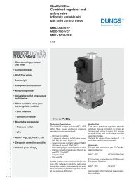
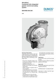
Technical description<br />
The DUNGS <strong>High</strong> <strong>Flow</strong> <strong>Safety</strong> <strong>Valve</strong> is<br />
a single-<strong>stage</strong> automatic butterfly valve<br />
according to EN 161 for gas burners, thermoprocess<br />
applications, gas engines and<br />
other gas-consuming equipment.<br />
- max. operating pressure up to 3 or 5 bar<br />
(300 or 500 kPa)<br />
- normally closed<br />
- fast opening, fast closing<br />
- pneumatic <strong>drive</strong>, single-action<br />
- mountable closed position signal contact<br />
to monitor closed position of valve on<br />
request<br />
- flange connection as per DIN EN 1092<br />
- reliable function, rugged and maintenance-free<br />
- high flow rates with minor pressure<br />
losses<br />
- design without non-ferrous metals<br />
Application<br />
The butterfly valve is used for securing, limiting,<br />
shutting off and releasing gas supply to<br />
gas burners, thermoprocess applications,<br />
gas engines and other gas-consuming<br />
equipment.<br />
The DUNGS butterfly valve <strong>HFSV</strong>... is suitable<br />
for gases according to G 262, gases<br />
of gas families 1, 2, 3 according to G 260<br />
and other neutral gases.<br />
The <strong>HFSV</strong>... SG is suitable for special gas<br />
applications (depending on evaluation of<br />
gas analysis specific for the system).<br />
Approval<br />
EC type test approval as per EC Gas Appliance<br />
Directive:<br />
<strong>HFSV</strong>...<br />
CE-0085 BU0186<br />
EC type test approval as per EC Pressure<br />
Equipment Directive:<br />
<strong>HFSV</strong>...<br />
<strong>HFSV</strong>... SG...<br />
CE0036<br />
With manufacturer's<br />
declaration
<strong>HFSV</strong>.../14<br />
<strong>HFSV</strong>.../14 SG...<br />
<strong>Single</strong>-<strong>stage</strong> butterfly valve, normally closed, fast opening, fast closing.<br />
suitable for special gas applications (SG) : single-<strong>stage</strong> butterfly valve, normally closed, fast opening,<br />
fast closing<br />
Specifications<br />
Nominal diameters, DN 50 65 80 100 125 150 200 250 300<br />
Connection flange as per DIN EN 1092<br />
Max. operating pressure<br />
5 bar (500 kPa)<br />
SG version: 3 bar (300 kPa)<br />
Butterfly valve<br />
<strong>Valve</strong> as per EN 161, Class A, Group 2, single-<strong>stage</strong> mode<br />
Closing time<br />
< 1 s<br />
Opening time<br />
DN 50 - DN 150: < 1 s<br />
DN 200 - DN 300: ≤ 2.5 s<br />
Materials of gas-conveying parts <strong>HFSV</strong>.../14 <strong>HFSV</strong>.../14 SGH <strong>HFSV</strong>.../14 SGV<br />
Housing: GGG 40 GGG 40 GGG40<br />
Shaft: Stainless steel Stainless steel Stainless steel<br />
Washer: Stainless steel Stainless steel Stainless steel<br />
Seals: NBR HNBR Viton<br />
Voltage/frequency =(DC) 24 V - 28 V; ~(AC) 50 - 60 Hz 230 V -15 % + 10 %<br />
Rating / power consumption<br />
at ~(AC) 230 V, + 20 °C<br />
Taper action: 11 VA<br />
Operation: 6 VA<br />
Switch-on duration 100 %<br />
Degree of protection IP 65<br />
Electrical connection Plug connection as per DIN 175301-803<br />
Switching rate DN 50 - DN 125: max. 300/h<br />
DN 150 - DN 300: max. 180/h<br />
Ambient temperature -10 °C up to + 60 °C<br />
Medium temperature<br />
-10 °C up to + 55 °C<br />
Compressed air<br />
Medium temperature<br />
Gas<br />
Installation position<br />
Closed position signal contact<br />
Control air<br />
Compressed air connection G 1/4 G 1/4<br />
Nominal pressure control air<br />
6 - 8 bar (600 - 800 kPa)<br />
-15 °C up to + 60 °C<br />
SGH version: -15 °C bis + 120 °C<br />
SGV version: 0 °C bis + 150 °C<br />
Drive standing vertically to lying horizontally<br />
on request<br />
clean dry compressed air according to ISO 8573-1, Class 3 and 5, or nitrogen, with switching<br />
cycles ≥ 2/min lubrication, dew point min. 10 °C lower than ambient temperature<br />
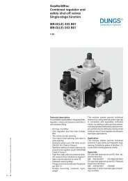
Dimensions [mm]<br />
<strong>HFSV</strong>... d<br />
f g<br />
b<br />
a 50*<br />
e<br />
c<br />
* Space requirement for mounting <strong>drive</strong><br />
h<br />
2 … 4
Type<br />
p max.<br />
[bar]<br />
DN<br />
Actuator<br />
Voltage<br />
Order<br />
Number<br />
Dimensions [mm]<br />
a b c d e f g h<br />
Weight<br />
[kg]<br />
<strong>HFSV</strong> 50050/14 5 50 EB 5.1 255 392 233 85 126 280 95 31,5 94 43 7,7<br />
<strong>HFSV</strong> 50065/14 5 65 EB 5.1 255 393 241 93,5 134,5 280 115 31,5 94 46 8,4<br />
<strong>HFSV</strong> 50080/14 5 80 EB 5.1 255 394 264 104,5 157 280 138 31,5 94 46 11,5<br />
~(AC) 230 V<br />
<strong>HFSV</strong> 50100/14 5 100 EB 5.1 255 395 274 115,5 167,5 280 158 31,5 94 52 12,7<br />
<strong>HFSV</strong> 50125/14 5 125 EB 6.1 255 396 301 128 180 351 188 39,5 103 56 14,9<br />
<strong>HFSV</strong> 50150/14 5 150 EB 6.1 255 397 324 152 203 351 210 39,5 103 56 17,9<br />
<strong>HFSV</strong> 50200/14 5 200 EB 8.1 255 398 366 177,5 228,5 408 268 45,5 108 60 25,6<br />
<strong>HFSV</strong> 50250/14 5 250 EB 12.1 255 399 452 213 266 661 320 69 130 68 51,2<br />
<strong>HFSV</strong> 50300/14 5 300 EB 12.1 255 400 477 238 290,5 661 370 69 130 78 58,6<br />
<strong>HFSV</strong> 50050/14 5 50 EB 5.1 255 318 233 85 126 280 95 31,5 94 43 7,7<br />
<strong>HFSV</strong> 50065/14 5 65 EB 5.1 255 319 241 93,5 134,5 280 115 31,5 94 46 8,4<br />
<strong>HFSV</strong> 50080/14 5 80 EB 5.1 255 320 264 104,5 157 280 138 31,5 94 46 11,5<br />
=(DC) 24 V<br />
<strong>HFSV</strong> 50100/14 5 100 EB 5.1 255 321 274 115,5 167,5 280 158 31,5 94 52 12,7<br />
<strong>HFSV</strong> 50125/14 5 125 EB 6.1 255 322 301 128 180 351 188 39,5 103 56 14,9<br />
<strong>HFSV</strong> 50150/14 5 150 EB 6.1 255 323 324 152 203 351 210 39,5 103 56 17,9<br />
<strong>HFSV</strong> 50200/14 5 200 EB 8.1 255 324 366 177,5 228,5 408 268 45,5 108 60 25,6<br />
<strong>HFSV</strong> 50250/14 5 250 EB 12.1 255 325 452 213 266 661 320 69 130 68 51,2<br />
<strong>HFSV</strong> 50300/14 5 300 EB 12.1 255 326 477 238 290,5 661 370 69 130 78 58,6<br />
<strong>HFSV</strong> 30050/14 SGH 3 50 EB 5.1 255 336 233 85 126 280 95 31,5 94 43 7,7<br />
<strong>HFSV</strong> 30065/14 SGH 3 65 EB 5.1 255 337 241 93,5 134,5 280 115 31,5 94 46 8,4<br />
<strong>HFSV</strong> 30080/14 SGH 3 80 EB 5.1 255 338 264 104,5 157 280 138 31,5 94 46 11,5<br />
=(DC) 24 V<br />
<strong>HFSV</strong> 30100/14 SGH 3 100 EB 5.1 255 339 274 115,5 167,5 280 158 31,5 94 52 12,7<br />
<strong>HFSV</strong> 30125/14 SGH 3 125 EB 6.1 255 340 301 128 180 351 188 39,5 103 56 14,9<br />
<strong>HFSV</strong> 30150/14 SGH 3 150 EB 6.1 255 341 324 152 203 351 210 39,5 103 56 17,9<br />
<strong>HFSV</strong> 30200/14 SGH 3 200 EB 8.1 255 342 366 177,5 228,5 408 268 45,5 108 60 25,6<br />
<strong>HFSV</strong> 30250/14 SGH 3 250 EB 12.1 255 343 452 213 266 661 320 69 130 68 51,2<br />
<strong>HFSV</strong> 30300/14 SGH 3 300 EB 12.1 255 344 477 238 290,5 661 370 69 130 78 58,6<br />
<strong>HFSV</strong> 30050/14 SGV 3 50 EB 5.1 255 327 233 85 126 280 95 31,5 94 43 7,7<br />
<strong>HFSV</strong> 30065/14 SGV 3 65 EB 5.1 255 328 241 93,5 134,5 280 115 31,5 94 46 8,4<br />
<strong>HFSV</strong> 30080/14 SGV 3 80 EB 5.1 255 329 264 104,5 157 280 138 31,5 94 46 11,5<br />
=(DC) 24 V<br />
<strong>HFSV</strong> 30100/14 SGV 3 100 EB 5.1 255 330 274 115,5 167,5 280 158 31,5 94 52 12,7<br />
<strong>HFSV</strong> 30125/14 SGV 3 125 EB 6.1 255 331 301 128 180 351 188 39,5 103 56 14,9<br />
<strong>HFSV</strong> 30150/14 SGV 3 150 EB 6.1 255 332 324 152 203 351 210 39,5 103 56 17,9<br />
<strong>HFSV</strong> 30200/14 SGV 3 200 EB 8.1 255 333 366 177,5 228,5 408 268 45,5 108 60 25,6<br />
<strong>HFSV</strong> 30250/14 SGV 3 250 EB 12.1 255 334 452 213 266 661 320 69 130 68 51,2<br />
<strong>HFSV</strong> 30300/14 SGV 3 300 EB 12.1 255 335 477 238 290,5 661 370 69 130 78 58,6<br />
3 … 4<br />
Driving function<br />
A solenoid valve with integrated draw-in<br />
of the exhaust is preceding the pneumatic<br />
<strong>drive</strong> as default.<br />
For switching the solenoid valve, the<br />
control connection of the valve is<br />
pressurized, the interior chamber of<br />
the cylinder is filled and the pistons<br />
move apart. During this process the<br />
motor shaft rotates counterclockwise,<br />
the valve is opened and the spring units<br />
are tensioned.<br />
Switching of the solenoid valve during a<br />
pressure loss or power failure deaerates<br />
the interior chamber, the spring units<br />
under tension are released and press<br />
the pistons together < 1 s.<br />
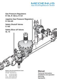
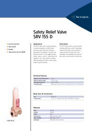
5.1.3 Pneumatischer Schwenkantrieb einfachwirkend Luftmoment,<br />
Wirkrichtung 0° - 90°<br />
Das Drehmoment (Md) ist das Ergebnis aus Kraft (F) x Hebelarm (L). Die Kraft wird durch Druck (P) bzw.<br />
durch Federkraft (F) auf die Kolbenfläche (A) erzeugt. Der wirksame Hebelarm (L) ist der Abstand von CL –<br />
Antriebswelle bis zur Berührungslinie Laufrolle / Schwinge.<br />
Durch die Konstruktion des Schwingenantriebs verändert sich der Hebelarm (L) im Schwenkbereich von 0°<br />
bis 90° kontinuierlich, der Drehmomentenverlauf ist „parabolisch“. Das maximale Drehmoment erreicht der<br />
Schwingenantrieb bei Position 0° und 90°, das minimale bei Position ca. 45°.<br />
Daraus ergeben sich ein maximal wirkendes Luftmoment bei 0° und ein minimal wirkendes Luftmoment bei<br />
90°, maximales Federmoment bei 90° und minimales Federmoment bei 0°.<br />
<br />
5.1.4 Pneumatischer Schwenkantrieb einfachwirkend Federmoment,<br />
Wirkrichtung 90° - 0°<br />
Compressed air Direction of rotation Compressed air Spring load Direction of rotation Spring load<br />
Das Drehmoment (Md) ist das Ergebnis aus Kraft (F) x Hebelarm (L). Die Kraft wird durch Druck (P) bzw.<br />
durch die Federkraft (F) auf die Kolbenfläche (A) erzeugt. Der wirksame Hebelarm (L) ist der Abstand von<br />
CL – Antriebswelle bis zur Berührungslinie Laufrolle / Schwinge. Durch die Konstruktion des<br />
Schwingenantriebs verändert sich der Hebelarm (L) im Schwenkbereich von 0° bis 90° kontinuierlich, der<br />
Drehmomentenverlauf ist „parabolisch“. Das maximale Drehmoment erreicht der Schwingenantrieb bei<br />
Position 0° und 90°, das minimale bei Position ca. 45°.<br />
Daraus ergeben sich ein maximal wirkendes Luftmoment bei 0° und ein minimal wirkendes Luftmoment bei<br />
90°, maximales Federmoment bei 90° und minimales Federmoment bei 0°.
<strong>High</strong> <strong>Flow</strong> <strong>Safety</strong> <strong>Valve</strong><br />
<strong>Pneumatic</strong> <strong>drive</strong><br />
<strong>Single</strong>-<strong>stage</strong><br />
<strong>HFSV</strong>...<br />
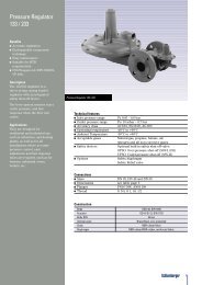
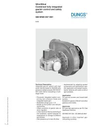
<strong>Flow</strong> diagram<br />
DN 50<br />
DN 65<br />
DN 80<br />
DN 100<br />
DN 125<br />
DN 150<br />
DN 200<br />
DN 250<br />
DN 300<br />
Basis + 15 °C, 1013 mbar, trocken<br />
Based on + 15 °C, 1013 mbar, dry<br />
Base + 15 °C, 1013 mbar, sec<br />
Base + 15 °C, 1013 mbar, secco<br />
10<br />
20<br />
40<br />
60 80 100<br />
Vn [m 3 /h] Luft / Air / Aria dv = 1,00<br />
200<br />
400 600 800 1000 2000 4000 6000 800010000 20000 40000 60000 80000 100000 200000 400000<br />
20 40 60 80 100 200 400 600 800 1000 2000 4000 6000 800010000 20000 40000 60000 80000 100000 200000 400000<br />
Vn [m 3 /h] Erdgas/Natural gas/Gaz Naturel/Gas metano dv = 0,65<br />
° °<br />
= V Luft/air<br />
x f<br />
V verwendetes Gas/gas used<br />
Gasart<br />
Type of gas<br />
Dichte<br />
Spec. Wgt.<br />
[kg/m 3 ]<br />
dv<br />
f<br />
Erdgas<br />
Natural gas<br />
0.81 0.65 1.24<br />
Dichte Luft<br />
Spec. weight air<br />
Stadtgas<br />
City gas<br />
0.58 0.47 1.46<br />
f =<br />
Dichte des verwendeten Gases<br />
Spec. weight of gas used<br />
Flüssiggas<br />
LPG<br />
Luft<br />
Air<br />
2.08 1.67 0.77<br />
1.24 1.00 1.00<br />
We reserve the right to make any changes in the interest of technical progress.<br />
Head Offices and Factory<br />
Karl Dungs GmbH & Co. KG<br />
Siemensstraße 6-10<br />
D-73660 Urbach, Germany<br />
Telephone +49 (0)7181-804-0<br />
Fax +49 (0)7181-804-166<br />
Postal address<br />
Karl Dungs GmbH & Co. KG<br />
Postfach 12 29<br />
D-73602 Schorndorf, Germany<br />
e-mail info@dungs.com<br />
Internet www.dungs.com<br />
4 … 4