

“Swiss Rectifier a Novel 3-Phase PFC Concept for High Power EV ...
“Swiss Rectifier a Novel 3-Phase PFC Concept for High Power EV ...
“Swiss Rectifier a Novel 3-Phase PFC Concept for High Power EV ...

Create successful ePaper yourself
Turn your PDF publications into a flip-book with our unique Google optimized e-Paper software.
<strong>“Swiss</strong> <strong>Rectifier</strong> a <strong>Novel</strong> 3-<strong>Phase</strong> <strong>PFC</strong> <strong>Concept</strong> <strong>for</strong> <strong>High</strong> <strong>Power</strong> <strong>EV</strong> Battery Charging Systems”<br />
ABSTRACT<br />
This paper introduces a new three-phase buck-type unity power factor converter appropriate <strong>for</strong> high power<br />
Electrical Vehicle (<strong>EV</strong>) battery charging mains interfaces. The characteristics of the novel converter, named the<br />
“SWISS <strong>Rectifier</strong>”, including the principle of operation, modulation strategy, suitable control structure, and<br />
dimensioning <strong>for</strong>mulas, are described in detail in this paper. Additionally, this rectifier solution is compared to a<br />
conventional buck-type <strong>PFC</strong> rectifier, by using a comprehensive evaluation method, where the total required<br />
semiconductor chip area and the total volume and weight of the passive components are assessed. Finally, the<br />
feasibility of the SWISS <strong>Rectifier</strong> <strong>for</strong> <strong>EV</strong> battery charging applications is demonstrated by means of measurements<br />
taken from a hardware demonstrator.<br />
I. INTRODUCTION<br />
Charging of Electrical Vehicle (<strong>EV</strong>) batteries inherently requires conversion of energy from the AC mains into DCquantities.<br />
Several charging voltage and power levels have been defined by different standardization organizations<br />
(IEC 61851, IEC62196, SAE J1772) [1]. Single-phase<br />
<strong>Power</strong> Factor Corrector (<strong>PFC</strong>) mains interfaces are<br />
commonly employed <strong>for</strong> low charging power levels<br />
(e.g. P < 5 kW), whereas <strong>for</strong> higher charging power levels<br />
3-phase <strong>PFC</strong> mains interfaces have to be applied. Possible<br />
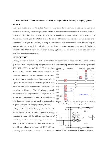
<strong>Power</strong> Electronics (PE) configurations <strong>for</strong> charging of <strong>EV</strong>s<br />
are given in Figure 1. The <strong>EV</strong> charger, typically<br />
implemented as two-stage systems, i.e. comprising a <strong>PFC</strong><br />
rectifier input stage followed by a DC/DC converter can be<br />
either integrated into the car (on-board) or accommodated<br />
in specially designed <strong>EV</strong> charging stations (off-board).<br />
Figure 1: Overview of basic power electronics<br />
converter topologies <strong>for</strong> <strong>EV</strong> charging systems.<br />
In the particular case of fast charging stations (off-board),<br />
the PE system should be able to guarantee voltage<br />
adaptation to cope with the different specifications of<br />
several types of vehicles. Typically, <strong>for</strong> AC mains<br />
operating at 400V or 480V (line-to-line rms), <strong>EV</strong> chargers<br />
with DC-bus voltage in the range of 250V-450V are<br />
commonly used. Buck-type 3-phase <strong>PFC</strong> rectifiers are<br />
Figure 2: Basic configuration of the SWISS <strong>Rectifier</strong>.
appropriate <strong>for</strong> high power <strong>EV</strong> chargers, as a direct connection to<br />
the DC-bus could be used. If isolation of the <strong>PFC</strong> output from the<br />
DC-bus is desired due to safety considerations, this could be<br />
facilitated by an isolated DC/DC converter connected in series,<br />
which could additionally be used <strong>for</strong> voltage level adaptation [2].<br />
Compared to boost-type topologies, buck-type ones provide a<br />
wider output voltage control range, while maintaining <strong>PFC</strong><br />
capability at the input, and allowing <strong>for</strong> dynamic current limitation<br />
[3]. In addition, 3-phase boost rectifiers produce an output voltage<br />
too high to directly feed the DC-bus (typically 700V-800V),<br />
requiring a step-down DC/DC converter at their output.<br />
This paper introduces a new 3-phase buck-type <strong>PFC</strong> rectifier<br />
topology, named as “SWISS <strong>Rectifier</strong>” [4] [5] (cf. Figure 2),<br />
appropriate <strong>for</strong> high power <strong>EV</strong> battery charging systems (coloured<br />
AC/DC converter blocks in Figure 1). Other suitable applications<br />
include power supplies <strong>for</strong> telecommunication systems, future<br />
more electric aircraft, variable speed AC drives and high power<br />
lighting systems. The characteristics of the new topology, which<br />
constitutes a new 3-phase active third harmonic injection rectifier<br />
and a suitable control stage, are presented in Section II.<br />
Additionally, the methods <strong>for</strong> calculating losses of all the<br />
Figure 3: The four conduction states of the<br />
SWISS <strong>Rectifier</strong> <strong>for</strong> u a >u b >u c .<br />
components, semiconductors and passives, are given. In Section III, the SWISS <strong>Rectifier</strong> is systematically compared<br />
with the 6-switch buck-type rectifier, which is a conventional buck-type <strong>PFC</strong> rectifier approach. Finally, in Section<br />
IV, measurements taken from constructed hardware prototypes are used to confirm the theoretical considerations.<br />
II. SWISS RECTIFIER: A NEW 3-PHASE AC/DC BUCK-TYPE CONVERTER<br />
Figure 2 shows the basic circuit configuration of the SWISS <strong>Rectifier</strong>, which was derived from a 3-phase boost-type<br />
active third harmonic injection rectifier proposed by [6]. With this new buck-type topology and a relatively low<br />
complexity control stage, not only controlled output voltage can be achieved, but also unity power factor operation.<br />
Four different conduction states can be defined by T + and T - within a pulse period, where the active current<br />
injection occurs always into only one mains phase as illustrated in Figure 3 <strong>for</strong> the interval ωt ϵ [0,π/3] (u a >u b >u c ).<br />
The proper selection of the switching states of T + and T - allows control over the current ripples across the inductor L
and the injection current, i y . Accordingly, the converter can<br />
be strategically modulated in order to minimize the current<br />
ripple of i y or of the output current I DC . Sinusoidal mains<br />
currents (i a =Gu a , i b =Gu b and i c =Gu c ) can be achieved if the<br />
duty cycles of T + , k 1 , and T - , k 2 , are defined as follows:<br />
k<br />
u<br />
max( u , u , u )<br />
a b c<br />
1 pn 2 2 2<br />
ua ub uc<br />
and<br />
k<br />
u<br />
min( u , u , u )<br />
a b c<br />
2 pn 2 2 2<br />
ua ub uc<br />
Figure 4: Circuit operation <strong>for</strong> interval u a >u b >u c .<br />
For instance, within the interval u a >u b >u c , k 1 and k 2 are<br />
driven by:<br />
u u u Gu u i i<br />
k <br />
pn a pn a pn a a<br />
1<br />
u 2 2 2 2 2 2<br />
a<br />
ub uc G u P<br />
a<br />
ub uc<br />
o<br />
IDC<br />
<br />
<br />
and<br />
k<br />
u u u Gu u i i<br />
<br />
. The<br />
pn c pn c pn c c<br />
2<br />
u 2 2 2 2 2 2<br />
a<br />
ub uc Gua u P<br />
b<br />
uc<br />
o<br />
IDC<br />
circuit equivalent of the possible conduction states (cf. Figure 3) is shown in Figure 4, where the converter current<br />
<strong>for</strong>mation is given by i 1k I 1k I i . This mathematical expression combined with the modulation<br />
y 1 DC 2 DC b<br />
definition k 1 =i a /I DC and k 2 =-i c /I DC , leads to i a +i b +i c =0, confirming the resistive mains behavior.<br />
A suitable feedback PWM control structure, EMI filtering, and the main converter dimensioning <strong>for</strong>mulas, which<br />
include the average and rms current values of the power semiconductors, are given in Figure 5. In the proposed<br />
control, by setting the PWM modulator <strong>for</strong> T + and T - to operate with in-phase carriers, the current ripple across i y<br />
will be reduced while the output current I DC ripple will be maximized. For interleaved operation of these carriers, the<br />
opposite will occur. The simulation results describing the principle of operation of the SWISS <strong>Rectifier</strong> are shown in<br />
Figure 6. The converter specification given in Table I is considered in the simulation where operation with in-phase<br />
or interleaved PWM carriers, and load steps (from 5 kW to 10 kW), are presented. As can be observed, the results<br />
demonstrate that the line currents, i a,b,c , can effectively follow the sinusoidal input voltages, u a,b,c , even in case of<br />
<br />
<br />
Figure 5: SWISS <strong>Rectifier</strong>: PWM control structure, EMI filtering and current stress across the semiconductors.
Table. I- SWISS rectifier specifications.<br />
Input voltage, u a,b,c : 230Vrms<br />
Input frequency, f in : 50Hz<br />
Switching frequency, f S : 72kHz<br />
Output power, P 0 : 10kW<br />
Output capacitor, C 0 : 400µF<br />
Inductor, L:<br />
300µH<br />
load steps, attesting the feasibility of the<br />
proposed rectifier and PWM control. More<br />
details <strong>for</strong> this system, including the EMI<br />
emissions modelling and filter design, as well<br />
as the control analysis, will be given in the<br />
final paper.<br />
III. COMPARATIVE <strong>EV</strong>ALUATION<br />
In order to evaluate and compare the SWISS<br />
<strong>Rectifier</strong> with a standard buck-type AC/DC<br />
converter, i.e. the 6-switch buck-type <strong>PFC</strong><br />
rectifier (cf. Figure 7), several normalized<br />
per<strong>for</strong>mance indices are defined. Based on<br />
these per<strong>for</strong>mance metrics a comparative<br />
Figure 6: Simulation results <strong>for</strong> SWISS rectifier operating with inphase<br />
or interleaved PWM carriers and load steps (5kW to 10kW).<br />
evaluation of the proposed systems is<br />
per<strong>for</strong>med graphically, as illustrated in<br />
Figure 8. An advantageous system would preferably cover the smallest area in the selected graphical representation.<br />
According to the results, the SWISS <strong>Rectifier</strong> is the topology of choice <strong>for</strong> a buck-type <strong>PFC</strong> of an <strong>EV</strong> charger.<br />
Figure 7: <strong>Power</strong> circuit structure of a conventional 6-switch<br />
buck-type <strong>PFC</strong> rectifier and dimensioning <strong>for</strong>mulas.<br />
Figure 8: Comparative evaluation of 3-phase <strong>PFC</strong><br />
buck rectifier topologies <strong>for</strong> <strong>EV</strong> charging systems.
In the final paper, a more comprehensive evaluation method <strong>for</strong> <strong>PFC</strong> rectifier systems will be introduced, where the<br />
total required semiconductor chip area and the total volume and weight of the passive components will be assessed.<br />
This approach not only provides a distinct Figure-of-Merit <strong>for</strong> comparison, but also enables the semiconductor costs,<br />
efficiency, and power density of the different topologies to be determined.<br />
IV. EXPERIMENTAL RESULTS<br />
In this section, the feasibility of the SWISS <strong>Rectifier</strong> and the 6-switch buck-type <strong>PFC</strong> rectifier <strong>for</strong> <strong>EV</strong> battery<br />
charging systems is demonstrated by measurements taken from constructed hardware prototypes. In this Digest only<br />
results of the experimental tests carried out <strong>for</strong> the latter rectifier are shown. However, in the final version of this<br />
paper, the prototype and experimental results <strong>for</strong> the SWISS <strong>Rectifier</strong> will also be presented.<br />
In Figure 9(a), an ultra-efficient (≈99%) 6-switch buck-type rectifier prototype is shown. The power density of this<br />
system is 2.2 kW/dm 3 . Figure 9(b) presents the measured sinusoidal input currents <strong>for</strong> 4.5 kW operation. The results<br />
obtained with the prototype confirm the operation and advantages of this system <strong>for</strong> <strong>EV</strong> applications.<br />
i a i b i c<br />
(a)<br />
(b)<br />
Figure 9: (a) 6-switch buck-type rectifier prototype and (b) experimental results.<br />
5A/Div<br />
2ms/Div<br />
V. CONCLUSIONS and FINAL PAPER<br />
This paper proposes a novel 3-phase unity power factor AC/DC converter appropriate not only <strong>for</strong> high power <strong>EV</strong><br />
battery charging systems, but also power supplies <strong>for</strong> telecommunication systems, future more electric aircraft,<br />
variable speed AC drivers and high power lighting systems. The converter concept, named as “SWISS <strong>Rectifier</strong>”, is<br />
comprehensively compared with a conventional 6-switch buck-type <strong>PFC</strong> rectifier. According to the results, the<br />
SWISS <strong>Rectifier</strong> is the topology of choice <strong>for</strong> a buck-type <strong>PFC</strong> mains interface of an <strong>EV</strong> battery charger.<br />
In the final version of this paper, the requirements <strong>for</strong> mains interface converters in <strong>EV</strong> battery charging applications<br />
will be described in detail. More in<strong>for</strong>mation <strong>for</strong> the SWISS <strong>Rectifier</strong>, including the EMI emissions modelling and<br />
filter design, as well as the control analysis, will be given. In addition, a detailed analysis of component losses <strong>for</strong> 10<br />
kW systems employing Si and SiC semiconductor devices will be shown. Finally, the prototype and experimental<br />
results <strong>for</strong> a 10 kW SWISS <strong>Rectifier</strong> will be presented.
REFERENCES<br />
[1] D. Aggeler, F. Canales, H. Zelaya, A. Coccia, N. Butcher, and O. Apeldoorn, “Ultra-Fast DC-Charger<br />
Infrastructures <strong>for</strong> <strong>EV</strong>-Mobility and Future Smart Grids”, Proc. Of the Innovative Smart Grid Techn. Conf.<br />
Europe (ISGT 2010), 2010.<br />
[2] A. Kuperman, U. Levy, J. Goren, A. Zafranski and A. Savernin, “<strong>High</strong> <strong>Power</strong> Li-Ion Battery Charger <strong>for</strong><br />
Electric Vehicle”, Proc. Of the 7th Int. Conf. Workshop Compatibility and <strong>Power</strong> Electron. (CPE 2011),<br />
2011.<br />
[3] A. Stupar, T. Friedli, J. Miniböck, and J.W. Kolar, “Towards a 99% Efficient Three-<strong>Phase</strong> Buck-Type <strong>PFC</strong><br />
<strong>Rectifier</strong> <strong>for</strong> 400 V DC Distribution Systems”, Proc. Of the 25th Ann. IEEE Appl. <strong>Power</strong> Electron. Conf.<br />
and Exp. (APEC 2010), 2010.<br />
[4] J. W. Kolar, M. Hartmann, T. Friedli, “ Hybrider Dreiphasiger AD/DC-Konverter und Verfahren zu dessen<br />
Steuerung”. Patent application nr CH00298/11, 2011.<br />
[5] J. W. Kolar, M. Hartmann, and T. Friedli, “Tutorial: Three-<strong>Phase</strong> <strong>PFC</strong> <strong>Rectifier</strong> and AC-AC Converter<br />
Systems”, Proc. Of the 25th Ann. IEEE Appl. <strong>Power</strong> Electron. Conf. and Exp. (APEC 2010), 2010.<br />
[6] J. C. Salmon, “Comparative evaluation of circuit topologies <strong>for</strong> 1-phase and 3-phase boost rectifiers<br />
operated with a low current distortion,” Proc. of Canadian Conference on Electrical and Computer<br />
Engineering, Halifax, Canada, September 1994.


