Consolidated - Catalog 1700 series
Consolidated - Catalog 1700 series
Consolidated - Catalog 1700 series

You also want an ePaper? Increase the reach of your titles
YUMPU automatically turns print PDFs into web optimized ePapers that Google loves.
<strong>1700</strong><br />
Scope of Design<br />
CONSOLIDATED Maxiflow ® high pressure safety valves are<br />
premium products that are installed on a majority of<br />
power generating stations worldwide to protect boilers<br />
from overpressure conditions.<br />
Table of Contents<br />
Scope of Design . . . . . . . . . . . . . . . . . . . . . .<strong>1700</strong>.1<br />
Materials . . . . . . . . . . . . . . . . . . . . . . . . . . .<strong>1700</strong>.8<br />
Dimensions & Weights (USCS) . . . . . . . . . . . . .<strong>1700</strong>.19<br />
Dimensions & Weights (metric) . . . . . . . . . . . .<strong>1700</strong>.25<br />
Pressure/Temperature (USCS) . . . . . . . . . . . .<strong>1700</strong>.32<br />
Pressure/Temperature (USCS) Alternate . . . . .<strong>1700</strong>.37<br />
Orifice Capacities . . . . . . . . . . . . . . . . . . . . . .<strong>1700</strong>.42<br />
Hydrostatic Test Plug . . . . . . . . . . . . . . . . . . .<strong>1700</strong>.67<br />
<strong>1700</strong><br />
<strong>1700</strong>.1<br />
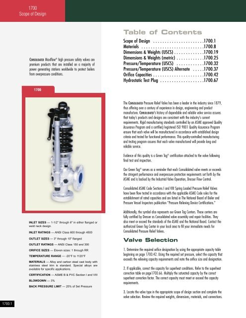
INLET SIZES — 1-1/2" through 6" in either flanged or<br />
weld neck design.<br />
INLET RATINGS — ANSI Class 600 through 4500<br />
OUTLET SIZES — 3" through 10" flanged<br />
OUTLET RATINGS — ANSI Class 150 and 300<br />
ORIFICE SIZES — Eleven sizes: 1 through RR<br />
TEMPERATURE RANGE — -20°F to 1120°F<br />
MATERIALS — Alloy and carbon steel cast body with<br />
stainless steel trim is standard. Special alloys are<br />
available for specific applications.<br />
CERTIFICATION — ASME B & PVC Section I and VIII<br />
BLOWDOWN — 3%<br />
BACK PRESSURE LIMIT — 25% of Set Pressure<br />
The CONSOLIDATED Pressure Relief Valve has been a leader in the industry since 1879,<br />
thus offering over a century of experience in design, engineering and product<br />
manufacture. CONSOLIDATED’S history of dependable and reliable valve service assures<br />
that today’s products and designs are consistent with the industry’s current<br />
requirements. Rigid manufacturing standards controlled by an ASME approved Quality<br />
Assurance Program and a certified/registered ISO 9001 Quality Assurance Program<br />
ensure that each valve will be manufactured in accordance with established design<br />
criteria and tested for functional performance. This quality-controlled manufacturing<br />
and testing program assures that each valve manufactured will provide long and<br />
reliable service.<br />
Evidence of this quality is a Green Tag ® certification attached to the valve following<br />
final test and inspection.<br />
Our Green Tag ® serves as a reminder that each <strong>Consolidated</strong> valve meets or exceeds<br />
the stringent performance and overpressure protection requirements set forth by the<br />
ASME and is backed by the Industrial Valve Operation, Dresser Flow Control.<br />
<strong>Consolidated</strong> ASME Code Sections I and VIII Spring Loaded Pressure Relief Valves<br />
have been flow tested in accordance with the applicable ASME Code rules for the<br />
establishment of rated capacities and are listed in The National Board of Boiler and<br />
Pressure Vessel Inspectors publication “Pressure Relieving Device Certifications.”<br />
Additionally, the symbol also represents our Green Tag Centers. These centers are<br />
fully certified by Dresser as <strong>Consolidated</strong> valve assembly and repair facilities. They<br />
also meet or exceed the standards of the ASME and the National Board. Contact the<br />
authorized Green Tag Center in your local area to fill your immediate needs for<br />
<strong>Consolidated</strong> Pressure Relief Valves.<br />
Valve Selection<br />
1. Determine the required orifice designation by using the appropriate capacity table<br />
beginning on page <strong>1700</strong>.42. Using the required set pressure, select the capacity that<br />
exceeds the relieving capacity requirements and note the orifice size and designation.<br />
2. If applicable, correct the capacity for superheat conditions. Refer to the superheat<br />
correction table on page<strong>1700</strong>.66. Multiply the saturated capacity by the correct<br />
superheat correction factor. The correct capacity must meet or exceed the capacity<br />
requirements.<br />
3. Locate the valve type in the appropriate scope of design section and complete the<br />
valve selection. Review the required weights, dimensions, materials, and connections.