MATERIALS AND SYSTEMS
MATERIALS AND SYSTEMS
MATERIALS AND SYSTEMS

Create successful ePaper yourself
Turn your PDF publications into a flip-book with our unique Google optimized e-Paper software.
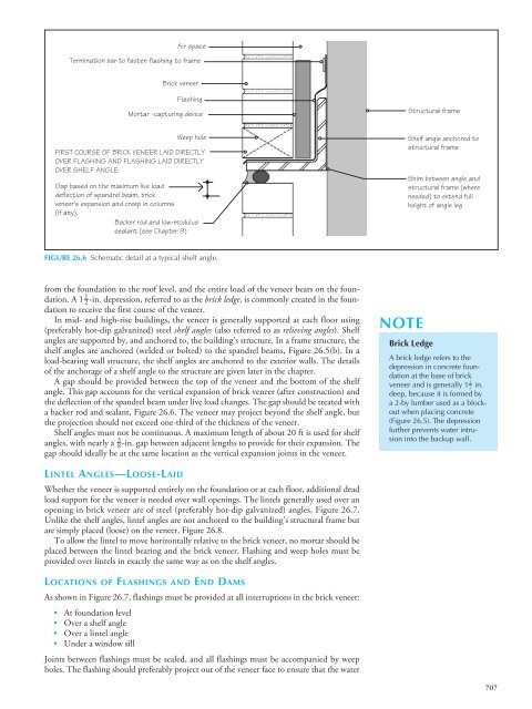
Air space<br />
Termination bar to fasten flashing to frame<br />
Brick veneer<br />
Flashing<br />
Mortar -capturing device<br />
Structural frame<br />
Weep hole<br />
FIRST COURSE OF BRICK VENEER LAID DIRECTLY<br />
OVER FLASHING <strong>AND</strong> FLASHING LAID DIRECTLY<br />
OVER SHELF ANGLE<br />
Gap based on the maximum live load<br />
deflection of spandrel beam, brick<br />
veneer's expansion and creep in columns<br />
(if any).<br />
Backer rod and low-modulus<br />
sealant (see Chapter 9)<br />
Shelf angle anchored to<br />
structural frame<br />
Shim between angle and<br />
structural frame (where<br />
needed) to extend full<br />
height of angle leg<br />
FIGURE 26.6 Schematic detail at a typical shelf angle.<br />
from the foundation to the roof level, and the entire load of the veneer bears on the foundation.<br />
A 1 2 -in. depression, referred to as the brick ledge, is commonly created in the foun-<br />
1<br />
dation to receive the first course of the veneer.<br />
In mid- and high-rise buildings, the veneer is generally supported at each floor using<br />
(preferably hot-dip galvanized) steel shelf angles (also referred to as relieving angles). Shelf<br />
angles are supported by, and anchored to, the building’s structure. In a frame structure, the<br />
shelf angles are anchored (welded or bolted) to the spandrel beams, Figure 26.5(b). In a<br />
load-bearing wall structure, the shelf angles are anchored to the exterior walls. The details<br />
of the anchorage of a shelf angle to the structure are given later in the chapter.<br />
A gap should be provided between the top of the veneer and the bottom of the shelf<br />
angle. This gap accounts for the vertical expansion of brick veneer (after construction) and<br />
the deflection of the spandrel beam under live load changes. The gap should be treated with<br />
a backer rod and sealant, Figure 26.6. The veneer may project beyond the shelf angle, but<br />
the projection should not exceed one-third of the thickness of the veneer.<br />
Shelf angles must not be continuous. A maximum length of about 20 ft is used for shelf<br />
3<br />
angles, with nearly a 8 -in. gap between adjacent lengths to provide for their expansion. The<br />
gap should ideally be at the same location as the vertical expansion joints in the veneer.<br />
NOTE<br />
Brick Ledge<br />
A brick ledge refers to the<br />
depression in concrete foundation<br />
at the base of brick<br />
1<br />
veneer and is generally 1<br />
2<br />
in.<br />
deep, because it is formed by<br />
a 2-by lumber used as a blockout<br />
when placing concrete<br />
(Figure 26.5). The depression<br />
further prevents water intrusion<br />
into the backup wall.<br />
LINTEL ANGLES—LOOSE-LAID<br />
Whether the veneer is supported entirely on the foundation or at each floor, additional dead<br />
load support for the veneer is needed over wall openings. The lintels generally used over an<br />
opening in brick veneer are of steel (preferably hot-dip galvanized) angles, Figure 26.7.<br />
Unlike the shelf angles, lintel angles are not anchored to the building’s structural frame but<br />
are simply placed (loose) on the veneer, Figure 26.8.<br />
To allow the lintel to move horizontally relative to the brick veneer, no mortar should be<br />
placed between the lintel bearing and the brick veneer. Flashing and weep holes must be<br />
provided over lintels in exactly the same way as on the shelf angles.<br />
LOCATIONS OF FLASHINGS <strong>AND</strong> END DAMS<br />
As shown in Figure 26.7, flashings must be provided at all interruptions in the brick veneer:<br />
• At foundation level<br />
• Over a shelf angle<br />
• Over a lintel angle<br />
• Under a window sill<br />
Joints between flashings must be sealed, and all flashings must be accompanied by weep<br />
holes. The flashing should preferably project out of the veneer face to ensure that the water<br />
707