MICRO Mill MF 70 Manual - Proxxon Tools
MICRO Mill MF 70 Manual - Proxxon Tools
MICRO Mill MF 70 Manual - Proxxon Tools

You also want an ePaper? Increase the reach of your titles
YUMPU automatically turns print PDFs into web optimized ePapers that Google loves.
7-10<br />
0<br />
5<br />
4<br />
3<br />
<strong>Proxxon</strong><strong>Tools</strong>.com<br />
<strong>MF</strong> <strong>70</strong><br />
1<br />
2<br />
Fr sen<br />
fl<br />
4-6<br />
NE-Metall<br />
1-3 5 5 5 5<br />
Stahl/Gu§<br />
Kunststoff<br />
Holz<br />
Bohren<br />
3 3 5 5<br />
0 0 5 5<br />
5 5 5 5<br />
1-3<br />
4-6<br />
7-10<br />
4 4 5 4<br />
3 3 4 3<br />
<strong>Manual</strong>
fl<br />
4-6<br />
7-10<br />
1-3<br />
4-6<br />
7-10<br />
3 3 4 3<br />
0<br />
1<br />
5<br />
3<br />
2<br />
4<br />
Ø<br />
7-10<br />
4 4 5 4<br />
3 3 4 3<br />
5<br />
0<br />
fl<br />
4-6<br />
7-10<br />
1-3<br />
4-6<br />
7-10<br />
Holz<br />
0<br />
1<br />
5<br />
2<br />
Holz<br />
4 4 5 4-6<br />
4<br />
1-3 5 5 5<br />
5<br />
4<br />
3<br />
Kunststo f<br />
Stahl/Gu§<br />
NE-Meta l<br />
fl<br />
sen Fr<br />
4-6<br />
7-10<br />
Bohren<br />
7-10<br />
3 3 4 3<br />
0<br />
1<br />
5<br />
3<br />
2<br />
4<br />
Ø<br />
4-6<br />
7-10<br />
1-3<br />
4-6<br />
7-10<br />
Holz<br />
0<br />
1<br />
5<br />
3<br />
2<br />
4<br />
17<br />
18<br />
3<br />
10<br />
11<br />
Fräsen<br />
Bohren<br />
NE-Meta l<br />
Stahl/Guß<br />
Kunststo f<br />
1-3 5 5 5 5<br />
4-6 3 3 5 5<br />
0 0 5 5<br />
5 5 5 5<br />
1-3<br />
7-10<br />
4-6<br />
Holz<br />
2<br />
1<br />
5<br />
19<br />
8<br />
6<br />
15<br />
4<br />
14<br />
13<br />
7<br />
16<br />
21 20<br />
12<br />
22<br />
9<br />
Fig. 1<br />
2<br />
Fr sen<br />
NE-Metall<br />
1-3 5 5 5 5<br />
Stahl/Gu§<br />
Kunststoff<br />
Fr sen<br />
Bohren<br />
NE-Meta l<br />
Stahl/Gu§<br />
Kunststo f<br />
1-3 5 5 3 3 0 0 5 5 5<br />
4 4 5 4<br />
Holz<br />
Bohren<br />
3 3 0 0 5 5 5<br />
4 4 5 4<br />
3 3 4 3<br />
3<br />
1<br />
3<br />
2<br />
1<br />
3<br />
Fräsen<br />
Bohren<br />
NE-Metall<br />
Stahl/Guß<br />
Kunststoff<br />
1-3 5 5 3 3 0 0 5 5 5<br />
4 4 5 4<br />
3 3 4 3<br />
2<br />
1<br />
Fig. 2<br />
Fig. 4 Fig. 4<br />
3<br />
1-3 5 5 5 5<br />
0 0 5 5<br />
3 5 3<br />
5<br />
Fig. 5 Fig. 6 Fig. 7<br />
- 2 -<br />
1<br />
2
Notes<br />
- 3 -
Operating Instructions<br />
Micro <strong>Mill</strong>ing Machine <strong>MF</strong> <strong>70</strong><br />
Dear Customer,<br />
By purchasing your PROXXON Micro <strong>Mill</strong>ing Machine<br />
<strong>MF</strong> <strong>70</strong>, you have chosen a good-quality, high-grade<br />
machine. The PROXXON <strong>MF</strong> <strong>70</strong> <strong>MICRO</strong> <strong>Mill</strong>ing Machine is<br />
equipped with the proven KT <strong>70</strong> microcoordinate table.<br />
This enables you to perform small, precise milling operations<br />
on metal, plastics or wood. In order to operate the<br />
milling machine and the accompanying accessories safely<br />
and correctly, please read the enclosed safety information<br />
and operating instructions prior to operation.<br />
This instruction manual covers:<br />
• safety regulations<br />
• operation and maintenance<br />
• spare parts list<br />
Please read carefully!<br />
Using this instruction manual will<br />
• make it easier for you to get used to the machine,<br />
• help prevent faults occurring due to improper use and<br />
• increase the service life of your machine.<br />
Keep this instruction manual in an easily accessible place.<br />
Only operate this machine if you are qualified to do so<br />
and follow the guidelines in this instruction manual.<br />
PROXXON does not accept responsibility for the safe functioning<br />
of the machine<br />
• if it is handled in a manner which constitutes improper<br />
use,<br />
• if it is used for other purposes which are not specified<br />
in the instruction manual,<br />
• if the safety regulations are not observed.<br />
Warranty claims are invalid if<br />
• the machine is incorrectly operated,<br />
• the machine has not been sufficiently maintained.<br />
In the interests of your safety, please always observe the<br />
safety regulations.<br />
Only use genuine PROXXON spare parts.<br />
We reserve the right to make further alterations for the<br />
purpose of technical progress.<br />
We wish you every success with your machine.<br />
General safety instructions:<br />
1. REMOVE ADJUSTING KEYS AND WRENCHES. Form<br />
habit of checking to see that keys and adjusting wrenches<br />
are removed from tool before turning it on.<br />
2. KEEP WORK AREA CLEAN. Cluttered areas and benches<br />
invite accidents.<br />
3. DON'T USE IN DANGEROUS ENVIRONMENT. Don't<br />
use power tools in damp or wet locations, or expose<br />
them to rain. Keep work area well lighted.<br />
4. KEEP CHILDREN AWAY. All visitors should be kept safe<br />
distance from work area.<br />
5. MAKE WORKSHOP KID PROOF with padlocks, master<br />
switches, or by removing starter keys.<br />
6. DON'T FORCE TOOL. It will do the job better and safer<br />
at the rate for which it was designed.<br />
- 4 -<br />
7. USE RIGHT TOOL. Don't force tool or attachment to<br />
do a job for which it was not designed.<br />
8. USE PROPER EXTENSION CORD. Make sure your<br />
extension cord is in good condition. When using an<br />
extension cord, be sure to use one heavy enough to<br />
carry the current your product will draw. An undersized<br />
cord will cause a drop in line voltage resulting in<br />
loss of power and overheating. Table 1 shows the correct<br />
size to use depending on cord length and nameplate<br />
ampere rating. If in doubt, use the next heavier<br />
gage. The smaller the gage number, the heavier the<br />
cord.<br />
Exception No. 1: The reference to the table and the<br />
table itself may be omitted if a statement indicating<br />
the appropriate gage and length is incorporated into<br />
the instruction.<br />
Exception No. 2: The information regarding extension<br />
cords need not be provided for a permanently<br />
connected tool.<br />
9. WEAR PROPER APPAREL. Do not wear loose clothing,<br />
gloves, neckties, rings, bracelets, or other jewelry<br />
which may get caught in moving parts. Non-slip<br />
footwear is recommended. Wear protective hair covering<br />
to contain long hair.<br />
Exception: The reference to gloves may be omitted<br />
from the instructions for a grinder.<br />
10. ALWAYS USE SAFETY GLASSES. Also use face or<br />
dust mask if cutting operation is dusty. Everyday<br />
eyeglasses only have impact resistant lenses, they are<br />
NOT safety glasses.<br />
11. SECURE WORK. Use clamps or a vise to hold work<br />
when practical. It's safer than using your hand and it<br />
frees both hands to operate tool.<br />
12. DON'T OVERREACH. Keep proper footing and<br />
balance at all times.<br />
13. MAINTAIN TOOLS WITH CARE. Keep tools sharp and<br />
clean for best and safest performance. Follow instructions<br />
for lubricating and changing accessories.<br />
14. DISCONNECT TOOLS before servicing; when changing<br />
accessories, such as blades, bits, cutters, and<br />
the like.<br />
15. REDUCE THE RISK OF UNINTENTIONAL STARTING.<br />
Make sure switch is in off position before plugging in.<br />
16. USE RECOMMENDED ACCESSORIES. Consult the<br />
owner's manual for recommended accessories. The<br />
use of improper accessories may cause risk of injury<br />
to persons.<br />
17. NEVER STAND ON TOOL. Serious injury could occur if<br />
the tool is tipped or if the cutting tool is unintentionally<br />
contacted.<br />
18. CHECK DAMAGED PARTS. Before further use of the<br />
tool, a guard or other part that is damaged should be<br />
carefully checked to determine that it will operate properly<br />
and perform its intended function -- check for<br />
alignment of moving parts, binding of moving parts,<br />
breakage of parts, mounting, and any other conditions<br />
that may affect its operation.<br />
A guard or other part that is damaged should be properly<br />
repaired or replaced.<br />
19. DIRECTION OF FEED. Feed work into a blade or cutter<br />
against the direction of rotation of the blade or<br />
cutter only.<br />
20. NEVER LEAVE TOOL RUNNING UNATTENDED. TURN<br />
POWER OFF. Don't leave tool until it comes to a complete<br />
stop.
GROUNDING INSTRUCTIONS:<br />
1. All grounded, cord-connected tools:<br />
In the event of a malfunction or breakdown, grounding<br />
provides a path of least resistance for electric current to<br />
reduce the risk of electric shock. This tool is equipped with<br />
an electric cord having an equipment-grounding conductor<br />
and a grounding plug. The plug must be plugged into a<br />
matching outlet that is properly installed and grounded in<br />
accordance with all local codes and ordinances. Do not<br />
modify the plug provided -- if it will not fit the outlet, have<br />
the proper outlet installed by a qualified electrician.<br />
Improper connection of the equipment-grounding<br />
conductor can result in a risk of electric shock. The<br />
conductor with insulation having an outer surface that is<br />
green with or without yellow stripes is the equipmentgrounding<br />
conductor. If repair or replacement of the<br />
electric cord or plug is necessary, do not connect the<br />
equipment-grounding conductor to a live terminal. Check<br />
with a qualified electrician or service personnel if the<br />
grounding instructions are not completely understood, or if<br />
in doubt as to whether the tool is properly grounded.<br />
Use only 3-wire extension cords that have 3prong<br />
grounding plugs and 3pole receptacles that accept the<br />
tool's plug.<br />
Repair or replace damaged or worn cord immediately.<br />
2. Grounded, cord-connected tools intended for use on a<br />
supply circuit having a nominal rating less than<br />
150 volts:<br />
This tool is intended for use on a circuit that has an outlet<br />
that looks like the one illustrated in Sketch A in Figure 28.<br />
The tool has a grounding plug that looks like the plug<br />
illustrated in Sketch A in Figure 28. A temporary adapter,<br />
which looks like the adapter illustrated in Sketches B and<br />
C, may be used to connect this plug to a 2-pole receptacle<br />
as shown in Sketch B if a properly grounded outlet is not<br />
available. The temporary adapter should be used only until<br />
a properly grounded outlet can be installed by a qualified<br />
electrician. The green-colored rigid ear, lug, and the like,<br />
extending from the adapter must be connected to a<br />
permanent ground such as a properly grounded outlet box.<br />
Grounding methods<br />
Table 1<br />
Minimum gage for cord<br />
Effective date for Table 1 changed from November 1, 1995 to<br />
November 11, 1996<br />
Ampere Rating Volts Total length of cord in feet<br />
More Not More AWG<br />
Than Than<br />
120 V 25 ft. 50 ft. 100 ft. 150 ft.<br />
240 V 50 ft. 100 ft. 200 ft. 300 ft.<br />
0 6 18 16 16 14<br />
6 10 18 16 14 12<br />
10 12 16 16 14 12<br />
12 16 14 12 Not Recommended<br />
Additional safety instructions :<br />
This milling machine is for indoor use only. Do not expose<br />
to rain or use in damp locations.<br />
Use only accessories recommended for this milling machine.<br />
Follow the instructions that accompany accessories.<br />
Use of improper accessories may cause hazards.<br />
Do not attempt to modify this tool or create accessories<br />
not recommended for use with this tool. Any such<br />
alternation or modification is misuse and could result in<br />
hazardous condition leading to possible serious injury.<br />
To avoid injury from unexpected starting or electrical<br />
shock, do not plug the power cord into a power source<br />
receptacle during unpacking and assembly. This cord must<br />
remain unplugged whenever you are working on the milling<br />
machine.<br />
If any part is missing or damaged, do not plug the milling<br />
machine in until the missing or damaged part is replaced,<br />
and assembly is complete. To avoid electrical shock, use<br />
only identical replacement parts when servicing grounded<br />
tools.<br />
For your safety, never connect the plug to the power<br />
source receptacle until the assembly and adjustment steps<br />
are completed, and you have read and understood the<br />
safety and operating instructions.<br />
GROUNDING<br />
PIN<br />
<br />
Fig. 28<br />
<br />
ADAPTER<br />
GROUNDING<br />
MEANS<br />
GROUNDING<br />
PIN<br />
METAL SCREW<br />
COVER OF GROUNDED<br />
OUTLET BOX<br />
<br />
<br />
To avoid injury from accidental start, make sure the switch<br />
is in the OFF position and the plug is not connected to the<br />
power source receptacle before changing any parts or<br />
tools (i. e. miller)<br />
To avoid injury from accidental start, make sure the switch<br />
is in the OFF position and the plug is not connected to the<br />
power source receptacle before making any adjustments.<br />
For your own safety, do not plug the tool into the power<br />
source receptacle or insert the switch key, until the parts<br />
are correctly installed and adjustments have been made.<br />
For your own safety, use only millers sized and recommended<br />
for this milling machine. Follow the instructions that<br />
accompany the millers.<br />
- 5 -
To avoid fire or toxic reaction, never use gasoline, naphtha,<br />
acetone, lacquer thinner, or similar highly volatile solvents<br />
to clean the milling machine.<br />
Do not allow brake fluids, gasoline, or penetrating oils to<br />
come in contact with the plastic parts. They contain<br />
chemicals that can damage or destroy plastics.<br />
Only qualified service technicians should do all electrical or<br />
mechanical repairs.<br />
When servicing use only PROXXON replacement parts.<br />
Use of any other parts may create a hazard or cause<br />
product damage.<br />
Any attempt to repair or replace electrical parts on this<br />
lathe may create a hazard unless repair is done by a<br />
qualified service technician. Repair service is available at<br />
your PROXXON service center (You find the address at the<br />
back of this manual)<br />
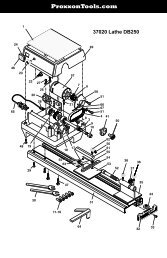
General view (Fig. 1):<br />
1. On / Off switch<br />
2. Speed control<br />
3. Scale for Z direction<br />
4. Spindle cover<br />
5. KT <strong>70</strong> work table (210 mm x <strong>70</strong> mm)<br />
6. Support<br />
7. Hole for securing base<br />
8. Adjusting screws<br />
9. Clamps<br />
10. Clamp screw<br />
11. Table for spindle speeds<br />
12. Collet chucks<br />
13. Handwheel for X direction<br />
14. Scale ring for X direction<br />
15. Handwheel for Y direction<br />
16. Scale ring for Y direction<br />
17. Handwheel for Z direction<br />
18. Scale ring for Z direction<br />
19. Moving scale for X direction<br />
20. Base plate<br />
21. Cutting guard<br />
22. Spanners<br />
Description of the machine<br />
The PROXXON <strong>MF</strong> <strong>70</strong> <strong>MICRO</strong> <strong>Mill</strong>ing Machine is the ideal<br />
machine for all fine and precision milling work for metals<br />
(cast iron, steel, brass, aluminium), plastics or wood. With<br />
the high spindle speed of 5,000 to 20,000 rpm (enabling<br />
the use of the smallest milling cutter diameters) in<br />
conjunction with the high-precision KT <strong>70</strong> microcoordinate<br />
table, all pre-conditions for precise and clean operation are<br />
fulfilled.<br />
The basic equipment includes:<br />
– <strong>Mill</strong>ing spindle with Z-pillar and stable base<br />
– Collet chuck block with collet chucks<br />
– (Ø 1.0; 1.5; 2.0, 2.4; 3.0 and 3.2 mm)<br />
– KT <strong>70</strong> microcoordinate table, complete<br />
– Clamp set with fastening materials<br />
– Fastening screws for KT <strong>70</strong> micro coordinate table<br />
– Auxiliary tools<br />
– Operating instructions and safety regulations<br />
Technical data<br />
Voltage:<br />
Power rating:<br />
Only for indoor use.<br />
Spindle speed<br />
Vertical adjustment travel<br />
Lateral adjustment travel<br />
Longitudinal adjustment travel<br />
Table size:<br />
Scale rings:<br />
Dimensions of T-grooves:<br />
Spacing of T-grooves:<br />
Size of base:<br />
Overall height:<br />
Weight approx.<br />
Noise emission:<br />
115 Volts, 60 Hz<br />
100 watt<br />
5,000 – 20,000 rpm<br />
<strong>70</strong> mm<br />
134 mm<br />
46 mm<br />
200 x <strong>70</strong> mm<br />
1 turn = 1 mm<br />
1 graduation line = 0.05 mm<br />
12 x 6 x 5 mm<br />
25 mm<br />
130 x 225 mm<br />
340 mm<br />
7 kg<br />
≤ <strong>70</strong> dB(A)<br />
Vibration ≤ 2.5 m/s 2<br />
Assembly of the milling machine<br />
Warning:<br />
To avoid injury from unexpected starting or electrical<br />
shock, do not plug the power cord into a power source<br />
receptacle during unpacking and assembly. This cord must<br />
remain unplugged whenever you are working on the milling<br />
machine.<br />
– Attach the compound-type table 1 (Fig. 2) to the base 2<br />
with the 4 x M4 Allen screws supplied.<br />
– The milling machine must now be fastened to a stable<br />
work surface with 4 screws 3.<br />
Operation<br />
Installation of the collet chucks<br />
Important:<br />
Disconnect the mains plug before changing tools.<br />
Tightening the union nut without a suitable shank inserted,<br />
damages the collet chuck.<br />
1. Block the spindle with a spanner and release union nut 1<br />
(Fig. 3).<br />
2. Insert the required collet chuck 2 using suitable inserting<br />
tool 3.<br />
3. Block milling spindle and re-tighten union nut.<br />
Note:<br />
All inserting tools must be tightened with as little protrusion<br />
as possible. Excessively protruding shanks vibrate and<br />
cause poor milling results.<br />
- 6 -
Setting the spindle speed<br />
The spindle speed can be adjusted continuously by means<br />
of the electronic control.<br />
In general:<br />
Large milling tool diameter = low speed<br />
Small milling tool diameter = high speed<br />
The correct spindle speeds are indicated on the table on<br />
the front of the milling machine.<br />
<strong>Mill</strong>ing<br />
Warning:<br />
Use only accessories recommended for this milling<br />
machine. Follow the instructions that accompany<br />
accessories. Use of improper accessories may cause<br />
hazards.<br />
Warning:<br />
Do not attempt to modify this tool or create accessories<br />
not recommended for use with this tool. Any such<br />
alternation or modification is misuse and could result in<br />
hazardous condition leading to possible serious injury.<br />
Important<br />
Always wear protective goggles when milling. Always<br />
observe the enclosed safety regulations.<br />
Maintenance<br />
Adjustment of guide play<br />
Warning:<br />
Disconnect the mains plug before making any<br />
adjustments.<br />
All 3 axes of the milling machine are equipped with an<br />
adjustable dovetail guide. If, after a time, a guide is found<br />
to have too much or too little play, the play can be reset via<br />
the adjusting screws (Fig. 7). In order to adjust the play in<br />
the X direction, first release the nut 1 (Fig. 7). Then set the<br />
play using the set screws 2. Lock by re-tightening the nut<br />
1. Adjustment of play for the other two axes is performed<br />
analogously.<br />
Note:<br />
Do not over-tighten the set screws as, otherwise, the guide<br />
may be damaged. Evenly tighten all the set screws.<br />
Accessories recommended for use with<br />
this tool<br />
Set of carbide millers No. 27116<br />
Carbide miller No. 28759<br />
1. Fasten the work piece with the clamps supplied or in a<br />
vice.<br />
2. Switch on milling machine at switch 1 (Fig. 4).<br />
3. Adjust the required milling depth using handwheel 2.<br />
(1 turn = 1 mm feed)<br />
4. Tighten clamp screw 3.<br />
5. Work with a suitable feed and with a suitable milling<br />
depth. The feed must always be against the cutting<br />
direction of the milling tool (Fig. 5).<br />
6. Release clamp screw 3 before readjusting the cutting<br />
depth (Fig. 4).<br />
Note:<br />
The <strong>MF</strong> <strong>70</strong> <strong>MICRO</strong> <strong>Mill</strong>ing Machine is designed for precise,<br />
fine machining. Therefore, adopt suitable milling depth and<br />
feed rate. Otherwise, poor quality milling results are to be<br />
expected. Furthermore, thermal damage may be caused to<br />
the electric motor due to continuous overloading.<br />
Adjustment of scale on compound-type table:<br />
Warning:<br />
Disconnect the mains plug before making any<br />
adjustments.<br />
The scale rings on the handwheels are moveable and can<br />
thus be set to zero without traversing the table. In addition<br />
to the scale rings, the KT <strong>70</strong> micro-compound-type table is<br />
equipped with a moveable scale for adjustment in the X<br />
direction 19 (Fig. 1).<br />
- 7 -