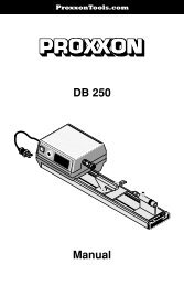
Manual KGS 80 MITER SAW - Proxxon Tools
Manual KGS 80 MITER SAW - Proxxon Tools
Manual KGS 80 MITER SAW - Proxxon Tools

You also want an ePaper? Increase the reach of your titles
YUMPU automatically turns print PDFs into web optimized ePapers that Google loves.
<strong>Proxxon</strong><strong>Tools</strong>.com<br />
<strong>KGS</strong> <strong>80</strong> <strong>MITER</strong> <strong>SAW</strong><br />
<br />
<br />
<br />
<br />
<strong>Manual</strong>
Fig. 1<br />
30<br />
0<br />
15<br />
15<br />
8<br />
3<br />
9<br />
10<br />
11<br />
5<br />
6<br />
13<br />
12<br />
4<br />
1<br />
2<br />
7<br />
30<br />
0<br />
15<br />
15<br />
8<br />
7<br />
9<br />
11<br />
5<br />
6<br />
10<br />
12<br />
3<br />
13<br />
2<br />
4<br />
1<br />
Fig. 2a<br />
Fig. 2b<br />
- 2 -
8<br />
7 12<br />
4<br />
9<br />
0<br />
15<br />
30<br />
1<br />
10<br />
15<br />
0<br />
15<br />
5<br />
30<br />
2<br />
6<br />
Fig. 3<br />
3<br />
Fig. 4<br />
2<br />
1<br />
30<br />
15<br />
0<br />
15<br />
3<br />
5<br />
4<br />
30<br />
15<br />
0<br />
15<br />
30<br />
1<br />
Fig. 5a<br />
Fig. 5b<br />
- 3 -
Operating instructions<br />
<strong>KGS</strong> <strong>80</strong> Miter Saw<br />
Contents:<br />
1 General safety notes . . . . . . . . . . . . . . . . . . . . . . . . . . . . . . . . . . 4<br />
2 Addditional safety instructions for Miter Saws. . . . . . . . . . . . . . . . . . . . . 6<br />
3 Grounding instructions . . . . . . . . . . . . . . . . . . . . . . . . . . . . . . . . . 6<br />
4 General view (fig. 1) . . . . . . . . . . . . . . . . . . . . . . . . . . . . . . . . . . 7<br />
5 Description of machine. . . . . . . . . . . . . . . . . . . . . . . . . . . . . . . . . 7<br />
6 Technical data . . . . . . . . . . . . . . . . . . . . . . . . . . . . . . . . . . . . . 8<br />
7 Before beginning work . . . . . . . . . . . . . . . . . . . . . . . . . . . . . . . . . 8<br />
8 Working with the <strong>KGS</strong> <strong>80</strong> Miter Saw . . . . . . . . . . . . . . . . . . . . . . . . . . 8<br />
8.1 Cutting capacity . . . . . . . . . . . . . . . . . . . . . . . . . . . . . . . . . . . . 8<br />
8.2 Sawing . . . . . . . . . . . . . . . . . . . . . . . . . . . . . . . . . . . . . . . . . 9<br />
8.2.1 General notes on setting the saw head . . . . . . . . . . . . . . . . . . . . . . . . 9<br />
8.2.2 Straight and mitre cuts . . . . . . . . . . . . . . . . . . . . . . . . . . . . . . . . . 9<br />
8.2.2.1 If you would like to produce straight cuts (see fig. 2a). . . . . . . . . . . . . . . . . 9<br />
8.2.2.2 If you would like to produce mitre cuts: (See fig. 2b): . . . . . . . . . . . . . . . . 10<br />
8.2.3 Working with the Length Stop (see fig. 4). . . . . . . . . . . . . . . . . . . . . . . 10<br />
9 Accessories . . . . . . . . . . . . . . . . . . . . . . . . . . . . . . . . . . . . . . 10<br />
10 Care and Maintenance . . . . . . . . . . . . . . . . . . . . . . . . . . . . . . . . 11<br />
10.1 Replacing the saw blade (see fig. 5a and 5b): . . . . . . . . . . . . . . . . . . . . 11<br />
10.2 Cleaning. . . . . . . . . . . . . . . . . . . . . . . . . . . . . . . . . . . . . . . . 11<br />
Dear Customer!<br />
Using these instructions<br />
• makes it easier to get familiar with the<br />
device<br />
• prevents malfunctions caused by improper<br />
handling, and<br />
• lengthens the service life of your device.<br />
Please keep these instructions readily accessible<br />
at all times.<br />
Use the device only when you have understood<br />
it exactly and always adhere to the<br />
instructions.<br />
PROXXON is not liable for the safe functioning<br />
of the device in cases of:<br />
• handling that does not conform to the usual<br />
usage,<br />
• purposes of use not designated in the<br />
instructions,<br />
• disregard of the safety instructions.<br />
You are not entitled to guarantee claims in<br />
cases of:<br />
• operator errors,<br />
• inadequate maintenance.<br />
For your own safety, please follow the safety<br />
instructions exactly.<br />
Use only genuine PROXXON replacement<br />
parts.<br />
We reserve the right to make improvements in<br />
the sense of technical progress. We wish you<br />
much success with the device.<br />
1 General safety notes<br />
KNOW YOUR POWER TOOL!<br />
Read and understand instruction manual!<br />
Understand your power tool´s application, limitations,<br />
and potential hazards.<br />
Warning!<br />
Failure to read all instructions and follow the<br />
general safety warnings and other safety<br />
- 4 -
warnings and cautions may result in serious<br />
personal injury.<br />
1. KEEP GUARDS IN PLACE and in working<br />
order.<br />
2. REMOVE ADJUSTING KEYS AND<br />
WRENCHES. Form habit of checking to<br />
see that keys and adjusting wrenches are<br />
removed from tool before turning it on.<br />
3. KEEP WORK AREA CLEAN. Cluttered<br />
areas and benches invite accidents.<br />
4. DON’T USE IN DANGEROUS ENVIRON-<br />
MENT. Don’t use power tools in damp or<br />
wet locations, or expose them to rain.<br />
Keep work area well lighted.<br />
5. KEEP CHILDREN AWAY. All visitors should<br />
be kept safe distance from work area.<br />
6. MAKE WORKSHOP KID PROOF with padlocks,<br />
master switches, or by removing<br />
starter keys.<br />
7. DON’T FORCE TOOL. It will do the job<br />
better and safer at the rate for which it<br />
was designed.<br />
8. USE RIGHT TOOL. Don’t force tool or<br />
attachment to do a job for which it was<br />
not designed.<br />
9. USE PROPER EXTENSION CORD. Make<br />
sure your extension cord is in good condition.<br />
When using an extension cord, be<br />
sure to use one heavy enough to carry the<br />
current your product will draw. An undersized<br />
cord will cause a drop in line voltage<br />
resulting in loss of power and overheating.<br />
Table 1 shows the correct size to use<br />
depending on cord length and nameplate<br />
ampere rating. If in doubt, use the next<br />
heavier gage. The smaller the gage number,<br />
the heavier the cord.<br />
Exception No. 1:<br />
The reference to the table and the table<br />
itself may be omitted if a statement indicating<br />
the appropriate gage and length is<br />
incorporated into the instruction.<br />
Exception No. 2:<br />
The information regarding extension cords<br />
need not be provided for a permanently<br />
connected tool.<br />
10. WEAR PROPER APPAREL. Do not wear<br />
loose clothing, gloves, neckties, rings,<br />
bracelets, or other jewelry which may get<br />
caught in moving parts. Nonslip footwear<br />
is recommended. Wear protective hair<br />
covering to contain long hair.<br />
Exception: The reference to gloves may be<br />
omitted from the instructions for a grinder.<br />
11. ALWAYS USE SAFETY GLASSES. Also<br />
use face or dust mask if cutting operation<br />
is dusty. Everyday eyeglasses only have<br />
impact resistant lenses, they are NOT<br />
safety glasses.<br />
12. SECURE WORK. Use clamps or a vise to<br />
hold work when practical. It’s safer than<br />
using your hand and it frees both hands to<br />
operate tool.<br />
13. DON’T OVERREACH. Keep proper footing<br />
and balance at all times.<br />
14. MAINTAIN TOOLS WITH CARE. Keep<br />
tools sharp and clean for best and safest<br />
performance. Follow instructions for lubricating<br />
and changing accessories.<br />
15. DISCONNECT TOOLS before servicing;<br />
when changing accessories, such as<br />
blades, bits, cutters, and the like.<br />
16. REDUCE THE RISK OF UNINTENTIONAL<br />
STARTING. Make sure switch is in off<br />
position before plugging in.<br />
17. USE RECOMMENDED ACCESSORIES.<br />
Consult the owner’s manual for recommended<br />
accessories. The use of improper<br />
accessories may cause risk of injury to<br />
persons.<br />
18. NEVER STAND ON TOOL. Serious injury<br />
could occur if the tool is tipped or if the<br />
cutting tool is unintentionally contacted.<br />
19. CHECK DAMAGED PARTS. Before further<br />
use of the tool, a guard or other part that<br />
is damaged should be carefully checked<br />
to determine that it will operate properly<br />
and perform its intended function – check<br />
for alignment of moving parts, binding of<br />
moving parts, breakage of parts, mounting,<br />
and any other conditions that may<br />
affect its operation.<br />
A guard or other part that is damaged<br />
should be properly repaired or replaced.<br />
20. DIRECTION OF FEED. Feed work into a<br />
blade or cutter against the direction of<br />
rotation of the blade or cutter only.<br />
21. NEVER LEAVE TOOL RUNNING UNAT-<br />
TENDED. TURN POWER OFF. Don’t leave<br />
tool until it comes to a complete stop.<br />
Table 1:<br />
Minimum gage for cord:<br />
Total length of<br />
cord in feet 25 ft 50 ft 100 ft 150 ft<br />
AWG: 18 16 16 14<br />
- 5 -
2 Addditional safety instructions for<br />
Miter Saws<br />
a) Wear eye protection.<br />
Projectiles thrown away from the machine<br />
could cause serious permanent eye damage.<br />
Always wear safety goggles, not<br />
glasses, complying with ANSI Z87.1 (or in<br />
Canada CSA Z94-3-M88). Everyday eyeglasses<br />
have only impact resistant lenses.<br />
They are not safety glasses! Safety goggles<br />
are available at many local retail<br />
stores. Glasses or goggles not in compliance<br />
with ANSI or CSA could seriously<br />
hurt you when they break.<br />
b) Keep hands out of path of saw blade.<br />
Avoid contact with any coasting blade. It<br />
can still cause severe injury.<br />
c) Do not operate saw without guards in<br />
place.<br />
Check blade guard for proper closing<br />
before each use. Do not operate saw if<br />
blade guard does not move freely and<br />
close instantly. Never clamp or tie the<br />
blade guard into the open position.<br />
d) Do not perform any operation freehand.<br />
The workpiece must be secured firmly<br />
against the turn base and guide fence with<br />
a vise during all operations. Never use<br />
your hand to secure the workpiece.<br />
Always use vise!<br />
e) Never reach around saw blade and<br />
keep fingers in a safe distance.<br />
f) Turn off tool and wait for saw blade to<br />
stop before moving workpiece or<br />
changing settings.<br />
g) Disconnect power (or unplug tool as<br />
applicable) before changing blade or<br />
servicing.<br />
Unplug your scroll saw before changing<br />
blades, adjustments, or performing any<br />
maintenance.<br />
h) Always remain alert when in the saw is<br />
in use. Inattention on the part of the operator<br />
may lead to serious injury.<br />
i) Before starting your work always<br />
inspect your workpiece<br />
Make sure there are no nails or foreign<br />
objects in the part of the work piece to be<br />
cut.<br />
j) Check damaged parts and watch the<br />
saw while it runs<br />
Before use of the tool, any part that is<br />
damaged should be carefully checked to<br />
ensure that it will operate properly and<br />
perform its intended function. If the saw<br />
makes an unfamiliar noise or vibrates<br />
excessively, stop immediately; turn the<br />
saw off. Unplug the saw! Check for alignment<br />
of moving parts, mounting, and any<br />
other conditions that may affect its operation.<br />
If any part is missing, broken or bent<br />
in any way, or any electrical parts don’t<br />
work properly, turn the saw off and unplug<br />
the saw. Do not restart until finding and<br />
fixing the problem correctly. All repairs,<br />
electrical or mechanical, should be<br />
attempted only by trained repairmen.<br />
k) Do not operate machine while under the<br />
influence of drugs, alcohol or medicamentation<br />
Never operate a machine when tired, or<br />
under the influence of drugs or alcohol or<br />
medicamentation. Full mental alertness is<br />
required at all times when running a<br />
machine.<br />
i) Do not remove jammed cutoff pieces<br />
until saw blade has stopped completely.<br />
Before freeing any jammed material or<br />
loose pieces from the turn-table of the<br />
saw, turn the machine off, wait for all moving<br />
parts to stop and unplug the saw!<br />
3 Grounding instructions<br />
In the event of a malfunction or breakdown,<br />
grounding provides a path of least resistance<br />
for electric current to reduce the risk of electric<br />
shock. This tool is equipped with an electric<br />
cord having an equipment-grounding conductor<br />
and a grounding plug. The plug must be<br />
plugged into a matching outlet that is properly<br />
installed and grounded in accordance with all<br />
local codes and ordinances.<br />
Do not modify the plug provided – if it will not<br />
fit the outlet, have the proper outlet installed<br />
by a qualified electrician.<br />
Improper connection of the equipmentgrounding<br />
conductor can result in a risk of<br />
electric shock. The conductor with insulation<br />
having an outer surface that is green with or<br />
without yellow stripes is the equipmentgrounding<br />
conductor. If repair or replacement<br />
- 6 -
of the electric cord or plug is necessary, do<br />
not connect the equipment-grounding conductor<br />
to a live terminal.<br />
Check with a qualified electrician or service<br />
personnel, if the grounding instructions are not<br />
completely understood, or if in doubt as to<br />
whether the tool is properly grounded. Use<br />
only 3-wire extension cords that have 3-prong<br />
grounding plugs and 3-pole receptacles that<br />
accept the tool’s plug.<br />
Repair or replace damaged or worn cord<br />
immediately.<br />
This tool is intended for use on a circuit that<br />
has an outlet that looks like the one illustrated<br />
in Sketch A in Figure 6.<br />
The tool has a grounding plug that looks like<br />
the plug illustrated in Sketch A in Figure 6. A<br />
temporary adapter, which looks like the<br />
adapter illustrated in Sketches B and C, may<br />
be used to connect this plug to a 2-pole<br />
receptacle as shown in Sketch B if a properly<br />
grounded outlet is not available. The temporary<br />
adapter should be used only until a properly<br />
grounded outlet can be installed by a<br />
qualified electrician. The green-colored rigid<br />
ear, lug, and the like, extending from the<br />
adapter must be connected to a permanent<br />
ground such as a properly grounded outlet<br />
box.<br />
GROUNDING<br />
PIN<br />
<br />
METAL SCREW<br />
COVER OF GROUNDED<br />
OUTLET BOX<br />
<br />
• crystalline silica from bricks and cement and<br />
other masonry products, and<br />
• arsenic and chromium from chemicallytreated<br />
lumber.<br />
Your risk from these exposures varies,<br />
depending on how often you do this type of<br />
work. To reduce your exposure to these chemicals:<br />
work in a well ventilated area, and work<br />
with approved safety equipment, such as<br />
those dust masks that are specially designed<br />
to filter out microscopic particles.<br />
Use a vacuum cleaner for wood dust collection<br />
as described in our manual whenever possible.<br />
Scope of supply:<br />
1 pc. Miter saw <strong>KGS</strong> <strong>80</strong>, fitted with TCT saw<br />
blade (24 teeth, also available as accessory<br />
28 734)<br />
1 pc. Longitudinal stop<br />
1 pc. Allen key<br />
1 pc. Instruction manual<br />
4 General view (fig. 1)<br />
1. Saw head<br />
2. Saw blade cover<br />
3. Locking lever<br />
4. Saw blade<br />
5. Device base<br />
6. Clamping screw<br />
7. Turntable<br />
8. Spindle for clamping fixture<br />
9. Limit stop<br />
10. Clamping fixture<br />
11. Scale<br />
12. Fastening bores<br />
13. Adjusting screw for saw head<br />
ADAPTER<br />
<br />
Figure 6:<br />
GROUNDING<br />
MEANS<br />
GROUNDING<br />
PIN<br />
<br />
5 Description of machine<br />
Thank you for purchasing the PROXXON <strong>KGS</strong><br />
<strong>80</strong> Miter Saw.<br />
WARNING:<br />
Some dust created by power sanding, sawing,<br />
grinding, drilling, and other construction activities<br />
contains chemicals known to the State of<br />
California to cause cancer, birth defects or<br />
other reproductive harm. Some examples of<br />
these chemicals are:<br />
• lead from lead-based paints,<br />
The saw is not only excellently suited for small<br />
yet fine applications for separating wood, nonferrous<br />
metals and plastics, but also larger<br />
round and square materials can be easily cut<br />
in two no matter whether with a straight cut or<br />
with a precise and freely adjustable mitre.<br />
The work piece is clamped in the integrated<br />
vice for sawing and separating. The centrically<br />
clamped jaws ensure that the imaginary centre<br />
- 7 -
line of the vice opening – therefore the centre<br />
of the work piece - will always “hit“ the centre<br />
of the saw blade independent of the selected<br />
work piece width.<br />
Clamping round materials is no problem. The<br />
prismatic groove ensures the safe and reliable<br />
clamping of round materials. For thin, yet relatively<br />
wide work pieces (up to 65 mm) there is<br />
another groove on the top of the clamping jaw.<br />
The round table itself is swivel-mounted: An<br />
angle of plus/minus 45° produces all desired<br />
mitres and the scale on the right also enables<br />
exact and easy monitoring of the angle setting.<br />
The round table has serrations every 15°,<br />
but any and all “intermediate steps“ can be<br />
set and fixed with a clamping fixture. Crosscutting<br />
work pieces by using the limit stop is<br />
also possible with this device.<br />
The saw head is kept in its upper home position<br />
by spring tension. Important: For even<br />
greater flexibility, the saw head can also be<br />
laterally adjusted on the side using a knurled<br />
screw. This minimises the “free” length of the<br />
work piece outside the vice jaws, and for<br />
angle cuts this ensures that the saw blade<br />
does not collide with the vice jaws.<br />
For saw head operation, i.e. to swivel the saw<br />
head down while working with the saw, the<br />
mechanical safety catch located on the saw<br />
head in its home position must be unlocked<br />
for your safety. To prevent accidental operation<br />
and therefore minimise the risk of injuries,<br />
the saw head is arrested in its upper position<br />
and can be unlocked with a small lever at the<br />
horizontal grip.<br />
This also unlocks the mechanical safety catch<br />
for the swivelling saw blade protection: This<br />
folds itself up when the saw head is lowered to<br />
the work piece. The ergonomically placed<br />
on/off button can then be pressed easily and<br />
without risk.<br />
6 Technical data<br />
Dimensions and weights:<br />
Device base: approx. 9” x 9”<br />
(230 mm x 230 mm)<br />
Device base height: approx. 2” (50 mm)<br />
Height:<br />
approx. 8 7 /16“ (215 mm)<br />
(in resting position of the<br />
separating head)<br />
Width:<br />
approx. 11 13 /16“ (300 mm)<br />
(saw head at far right)<br />
Jaw length of vice: 3 1 /8” (<strong>80</strong> mm)<br />
Span width: max. 1 6 /8 “ (45 mm)<br />
Weight:<br />
approx. 6 kg<br />
Ø saw blade: 3 1 /8”; max 3 11 /32”<br />
(<strong>80</strong> mm; max. 85 mm)<br />
Motor:<br />
Voltage:<br />
Power:<br />
No-Load speed:<br />
110-120 V<br />
50/60 Hz<br />
1.8 A<br />
5400/min<br />
7 Before beginning work<br />
NOTE:<br />
Safe and precise work is only then possible if<br />
the device has been properly fastened with<br />
screws to a worktop. There are drill holes in<br />
the heel plate for this purpose.<br />
CAUTION!<br />
When fixing or transporting the device, always<br />
disconnect the mains plug!<br />
DANGER!<br />
Never operate the Miter Saw without wearing<br />
protective goggles!<br />
Never use the Miter Saw to cut materials other<br />
than wood, non-ferrous metals or plastics.<br />
Only choose saw blades suitable for the material<br />
to be cut.<br />
8 Working with the <strong>KGS</strong> <strong>80</strong> Miter Saw<br />
8.1 Cutting capacity<br />
Work can begin after the device has been<br />
fixed to a stable base. Additional preparations<br />
are not necessary and the work piece to be<br />
separated can be clamped into the vice and<br />
cut in two. Please note the following maximum<br />
sizes in dependence on the sawing angle:<br />
How to read the table:<br />
If, for example, you would like to cut a 1 3 /16”<br />
inch squared timber in two at a 45° angle, it<br />
may only have a maximum depth of 3 /8” inch.<br />
Please note that these are only standard<br />
values.<br />
- 8 -
Cutting capacity at 90° Cutting capacity at 45° (mitre cut):<br />
(right-angled cut):<br />
For material<br />
thicknesses<br />
up to (inch)<br />
Maximum<br />
material width<br />
(inch)<br />
Round<br />
material:<br />
(inch)<br />
For material<br />
thicknesses<br />
up to (inch)<br />
Maximum<br />
material width<br />
(inch)<br />
Round<br />
material:<br />
(inch)<br />
3/8”<br />
11/16”<br />
13/16”<br />
1”<br />
2 9/16”<br />
2”<br />
1 9/16”<br />
1”<br />
Ø 1”<br />
3/16”<br />
3/8”<br />
9/16”<br />
3/4”<br />
1 13/32”<br />
1 3/16”<br />
1”<br />
11/16”<br />
Ø 3/4”<br />
8.2 Sawing<br />
8.2.1 General notes on setting the saw<br />
head<br />
To achieve the shortest possible clamping<br />
length of the clamped work piece, the position<br />
of the saw head can be adjusted by using the<br />
knurled screw 11 (fig. 2a/b). This enables the<br />
saw blade to be guided as close to the clamping<br />
fixture as possible. Cuts will then be especially<br />
clean and precise if there is only a small<br />
gap between the restraint and the saw blade<br />
level.<br />
Before every use, make certain that the saw<br />
head is not set so that the saw blade will collide<br />
with the jaws of the clamping fixture when<br />
swivelling the saw head down (e.g. by shutting<br />
down the saw head when machine is off. Caution:<br />
disconnect the mains plug here)! Risk of<br />
injury!<br />
CAUTION!<br />
Do not remove any cutting scraps or other<br />
work piece parts from the cutting area as long<br />
as the machine is running and the saw blade<br />
is not in its home position.<br />
8.2.2 Straight and mitre cuts<br />
8.2.2.1 If you would like to produce straight<br />
cuts (see fig. 2a)<br />
1. Make sure that turntable 1 (see fig. 2a) is<br />
in the 0° position: Arrow marking 2 must<br />
point to the 0° marking on scale 3 in the<br />
device base. If not, then please set as follows:<br />
(Caution: Please make sure that<br />
knurled screw 13 is released!)<br />
2. Release stop lever 4 by lifting it and guide<br />
turntable 1 to the corresponding position.<br />
Let go of stop lever 4.<br />
Caution! The turntable will lock in place at 0°.<br />
If necessary, move turntable back and forth a<br />
bit with released stop lever until the stop lever<br />
catches.<br />
3. Insert work piece 5 in clamping fixture 6,<br />
align and tighten. Pay attention to the<br />
desired length of the „free“ end!<br />
4. For perfect alignment, saw head 7 of the<br />
switched off (!) device after locking lever 8<br />
has been unlocked (pull to the front) can<br />
be swivelled down so far that saw blade 9<br />
at the automatic swivelled-away saw<br />
blade protection 10 just barely touches the<br />
work piece (see also fig. 3). This enables a<br />
better estimation of the future length of the<br />
work piece.<br />
5. For exact adjustment, saw head 7 can be<br />
finely toggled by using knurled screw 11.<br />
DANGER! WARNING!<br />
Please make sure here that the saw blade will<br />
never collide with the jaws of clamping fixture 6!<br />
Please note:<br />
Crosscutting with the supplied length stop is<br />
no problem! How this works is described in<br />
“Working with the Length Stop”.<br />
6. (See fig. 3). After locking lever 8 has been<br />
released and the on/off button 12 has been<br />
pressed, swivel saw head 7 down and cut<br />
the work piece into two as shown in Fig. 3.<br />
The saw blade protection swivels up.<br />
8.2.2.2 If you would like to produce mitre<br />
cuts: (See fig. 2b):<br />
1. Release knurled screw 13 and lift up stop<br />
lever 4. Now set turntable 1 to the desired<br />
angle. Please use scale 3 and orient yourself<br />
using arrow marking 2 on turntable 1.<br />
The 15° graduations are provided with ser-<br />
- 9 -
ations, and stop lever 4 must be released<br />
so that they can become effective. Intermediate<br />
settings can also be set and fixed<br />
using knurled screw 13.<br />
2. Insert work piece 5 in clamping fixture 6,<br />
align and tighten. Pay attention to the<br />
desired length of the „free“ end here as<br />
well!<br />
3. For perfect alignment, saw head 7 of the<br />
switched off (!) device after locking lever 8<br />
has been unlocked (pull to the front) can<br />
be swivelled down so far that saw blade 9<br />
at the automatic swivelled-away saw<br />
blade protection 10 just barely touches the<br />
work piece (see also fig. 3). This enables a<br />
better estimation of the future length of the<br />
work piece. For exact adjustment, the saw<br />
head can be finely toggled by using<br />
knurled screw 11.<br />
DANGER! WARNING!<br />
Please make sure that the saw blade will never<br />
collide with the jaws of clamping fixture 6!<br />
Please note:<br />
Crosscutting with the supplied length stop is<br />
no problem! How this works is described in<br />
“Working with the Length Stop”.<br />
4. After block lever 8 has been released and<br />
the on/off button 12 has been pressed,<br />
swivel saw head 7 down and cut the work<br />
piece in two as shown in fig. 3. The saw<br />
blade protection swivels up.<br />
NOTE!<br />
The rotational speed, and not the contact<br />
pressure, generates the high cutting performance!<br />
Never work with force! This places an<br />
unnecessary load on the machine mechanics<br />
and leads to bad results and increased wear!<br />
8.2.3 Working with the Length Stop<br />
(see fig. 4)<br />
The <strong>KGS</strong> <strong>80</strong> Miter Saw is supplied with an<br />
adjustable length stop 1. Any number of work<br />
pieces of equal length can be cut off. Work<br />
piece 2 to be cut off is inserted in clamping<br />
fixture 3, pushed up to the limit plate 4 and<br />
then clamped. After the work piece has been<br />
cut off and the vice has been loosened, the<br />
material is pushed up to the limit stop again,<br />
clamped with the vice and then cut off. This<br />
can be repeated any number of times.<br />
This is how to set the limit stop:<br />
1. Allen screw 5 is released using an Allen<br />
key (included in delivery). Limit stop 1 can<br />
then be pushed in guide 6 up to the<br />
desired length. Make sure that limit plate 4<br />
is properly aligned and that it hits the work<br />
piece correctly when “limit stopped”!<br />
2. Clamp limit stop 1 with Allen screw 5.<br />
If the limit stop is not required, it can be completely<br />
removed after releasing screw 5.<br />
The desired position of the limit stop can be<br />
determined, for example, by appropriately<br />
marking a work piece, clamping it so that the<br />
saw blade hits the marking exactly and then by<br />
aligning the limit stop accordingly. This enables<br />
the exact reproduction length for the desired<br />
number of the subsequent work pieces.<br />
CAUTION!<br />
After the work piece has been aligned and<br />
clamped, fold limit plate 4 away during work<br />
(see fig. 4) to prevent the separated work<br />
pieces from jamming!<br />
9 Accessories<br />
Replace damaged or worn saw blades immediately.<br />
They represent a safety risk and worsen<br />
the work result.<br />
Please use PROXXON accessories. NOTE:<br />
The use of improper accessories may cause<br />
hazards.<br />
Actually we provide:<br />
Super cut<br />
(NO 28 731) <strong>80</strong> teeth, 3 11 /32“ (85 mm) diameter<br />
x 1 /64“ x 13 /32“ bore (0.5 x 10 mm). Used on<br />
hard and soft woods or plastics.<br />
Tungsten carbide tipped (TCT)<br />
(NO 28 732) 36 teeth, 3 1 /8“ (<strong>80</strong> mm) diameter<br />
x 1 /16“ x 13 /32“ bore (1.6 x 10 mm). Used on<br />
balsa, ply, soft woods, plastics, aluminum,<br />
Polycarbonate and GFK.<br />
Tungsten carbide tipped (TCT)<br />
(NO 28 734) 24 teeth, 3 1 /8“ (<strong>80</strong> mm) diameter<br />
x 1 /16“ x 13 /32“ bore (1.6 x 10 mm). Used on aluminum,<br />
hard wood, laminates or plastics.<br />
Diamond coated<br />
(NO 28 735) 3 11 /32“ (85 mm) diameter x 1 /64“ x<br />
13<br />
/32“ bore (0.5 x 10 mm). Used on circuit<br />
boards or glassfiber reinforced plastics (GRP).<br />
Synthetic resin bonded cut-off wheel<br />
(NO 28 729) 3 1 /8“ (<strong>80</strong> mm) diameter x 1 /16“ x<br />
3<br />
/8“, bore (1.6 x 10 mm). For cutting wood,<br />
steel, non-ferrous metals and plastics.<br />
- 10 -
10 Care and Maintenance<br />
10.1 Replacing the saw blade<br />
(see fig. 5a and 5b):<br />
If the saw blade is worn or you wish to use<br />
another type or a cutting disc, you can quickly<br />
and easily exchange them.<br />
Please note:<br />
Replacement saw blades and a corundum<br />
cutting disc for the machine can be obtained<br />
on the market. Also observe the "Accessories"<br />
section of this manual.<br />
Please see our device catalogue or consult<br />
your nearest dealer!<br />
CAUTION!<br />
Disconnect the mains plug for all care and<br />
maintenance works!<br />
1. Unscrew Allen screw 1 in saw blade protection<br />
2 and fold saw blade protection up<br />
as shown in fig. 5a.<br />
2. Using an Allen key, unscrew screw 4 in the<br />
centre of saw blade 3 (see fig. 5b). Hold<br />
the shaft at the flat spot with an openended<br />
spanner, Attention: Left-handedthread!<br />
3. Remove old saw blade. Mind flat washer 5<br />
here.<br />
4. Attach new saw blade and tighten with flat<br />
washer 5 and screw 4.<br />
CAUTION!<br />
Pay close attention to the running direction of<br />
the saw blade. When viewed from the front<br />
side of the saw, the teeth must point downwards!<br />
Be careful when using the corundum cutting<br />
disc (accessories, item no.: 28 729):<br />
The corundum cutting disc is very sensitive to<br />
bending. Do not touch the disc when releasing<br />
or tightening the fastening screw. The disc<br />
breaks very easily.<br />
5. Fold down saw blade protection 2 once<br />
more and tighten using Allen screw 1.<br />
CAUTION!<br />
Disconnect the mains plug for all care and<br />
maintenance works!<br />
10.2 Cleaning<br />
CAUTION!<br />
Always disconnect the mains plug before<br />
doing any cleaning, setting, maintenance or<br />
repair works!<br />
NOTE:<br />
The machine is mostly maintenance free. For a<br />
long service life, the device should be cleaned<br />
after every use with a soft cloth, hand brush or<br />
a soft brush. Even a vacuum cleaner can be<br />
recommended. Ensure all ventilation slots are<br />
free from obstruction.<br />
External cleaning of the housing can be carried<br />
out using a soft, possibly moist cloth.<br />
While doing so, a mild detergent or other suitable<br />
cleansing agent can be used.<br />
WARNING!<br />
To avoid fire or toxic reaction, never use<br />
gasoline, naphtha, acetone, lacquer thinner, or<br />
similar highly volatile solvents to clean the<br />
scroll saw.<br />
Do not allow brake fluids, gasoline, or penetrating<br />
oils to come in contact with the plastic<br />
parts. They contain chemicals that can damage<br />
or destroy plastics!<br />
Also some of these products have low flash<br />
points and could explode if used to clean the<br />
saw.<br />
NEVER smoke while using solvents: Smoking<br />
near solvents could ignite an explosion or fire<br />
and cause serious injury.<br />
ALWAYS WORK in a well ventilated area to<br />
prevent the accumulation of dangerous fumes,<br />
continuesly supply the work area with a constant<br />
source of fresh air:<br />
Lack of ventilation while using solvents could<br />
cause serious personal health risks, fire, or<br />
environmental hazards.<br />
When servicing use only PROXXON replacement<br />
parts.<br />
Use of any other parts may create a hazard or<br />
cause product damage.<br />
Any attempt to repair or replace electrical<br />
parts on this tool may create a hazard unless<br />
repair is done by a qualified service technician.<br />
Repair service is available at your PROXXON<br />
service center (You find the address at<br />
address at the back of this manual).<br />
- 11 -