Manual DB 250 - Proxxon Tools
Manual DB 250 - Proxxon Tools
Manual DB 250 - Proxxon Tools

Create successful ePaper yourself
Turn your PDF publications into a flip-book with our unique Google optimized e-Paper software.
1<br />
2<br />
3<br />
5<br />
<strong>Proxxon</strong><strong>Tools</strong>.com<br />
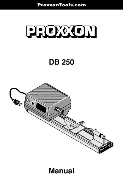
<strong>DB</strong> <strong>250</strong><br />
0<br />
4<br />
<strong>Manual</strong>
1<br />
2<br />
3<br />
4<br />
0<br />
5<br />
1<br />
2<br />
3<br />
4<br />
19<br />
0<br />
1 2<br />
3 4<br />
7<br />
8<br />
5<br />
5<br />
6<br />
9<br />
14<br />
Fig. 1<br />
13<br />
12<br />
11<br />
10<br />
1<br />
3<br />
2<br />
4<br />
Fig. 2<br />
Fig. 3<br />
Fig. 4<br />
Fig. 5<br />
- 2 -
1<br />
3<br />
2<br />
1<br />
2<br />
Fig. 6<br />
Fig. 7<br />
Fig. 8<br />
Fig. 9<br />
1<br />
2<br />
Fig. 10 Fig. 11<br />
- 3 -
Operating Instructions<br />
<strong>DB</strong> <strong>250</strong><br />
Instructions for the use of the Micro wood<br />
turning lathe <strong>DB</strong> <strong>250</strong><br />
Dear Customer,<br />
In order to be able to operate the wood turning lathe<br />
safely and correctly, please carefully read the following<br />
safety and operating instructions prior to use.<br />
This instruction manual covers:<br />
• safety regulations<br />
• operation and maintenance<br />
• spare parts list<br />
Please read carefully and become familiar with this entire<br />
instructions manual. Learn the tool´s applications, limitations<br />
and possible hazards.<br />
Using this instruction manual will<br />
• make it easier for you to get used to the machine,<br />
• help prevent faults occurring due to improper use and<br />
• increase the service life of your machine.<br />
Keep this instruction manual in an easily accessible<br />
place. Only operate this machine if you are qualified to do<br />
so and follow the guidelines in this instruction manual.<br />
PROXXON does not accept responsibility for the safe<br />
functioning of the machine<br />
• if it is handled in a manner which constitutes improper use,<br />
• if it is used for other purposes which are not specified in<br />
the instruction manual,<br />
• if the safety regulations are not observed.<br />
Warranty claims are invalid if<br />
• the machine is incorrectly operated,<br />
• the machine has not been sufficiently maintained.<br />
In the interests of your safety, please always observe the<br />
safety regulations.<br />
Only use genuine PROXXON spare parts.<br />
We reserve the right to make further alterations for the<br />
purpose of technical progress.<br />
We wish you every success with your machine.<br />
Safety instructions<br />
1. KEEP GUARDS IN PLACE and in working order.<br />
2. REMOVE ADJUSTING KEYS AND WRENCHES.<br />
Form habit of checking to see that keys and adjusting<br />
wrenches are removed from tool before turning it on.<br />
3. KEEP WORK AREA CLEAN. Cluttered areas and<br />
benches invite accidents.<br />
4. DON’T USE IN DANGEROUS ENVIRONMENT. Don’t<br />
use power tools in damp or wet locations, or expose<br />
them to rain. Keep work area well lighted.<br />
5. KEEP CHILDREN AWAY. All visitors should be kept<br />
safe distance from work area.<br />
6. MAKE WORKSHOP KID PROOF with padlocks,<br />
master switches, or by removing starter keys.<br />
7. DON’T FORCE TOOL. It will do the job better and<br />
safer at the rate for which it was designed.<br />
8. USE RIGHT TOOL. Don’t force tool or attachment to<br />
do a job for which it was not designed.<br />
9. USE PROPER EXTENSION CORD. Make sure your<br />
extension cord is in good condition. When using an<br />
extension cord, be sure to use one heavy enough to<br />
carry the current your product will draw. An<br />
undersized cord will cause a drop in line voltage<br />
resulting in loss of power and overheating. Table 1<br />
shows the correct size to use depending on cord<br />
length and nameplate ampere rating. If in doubt, use<br />
the next heavier gage. The smaller the gage number,<br />
the heavier the cord.<br />
10. WEAR PROPER APPAREL. Do not wear loose<br />
clothing, gloves, neckties, rings, bracelets, or other<br />
jewelry which may get caught in moving parts.<br />
Nonslip footwear is recommended. Wear protective<br />
hair covering to contain long hair.<br />
Exception: The reference to gloves may be omitted<br />
from the instructions for a grinder.<br />
11. ALWAYS USE SAFETY GLASSES. Also use face or<br />
dust mask if cutting operation is dusty. Everyday<br />
eyeglasses only have impact resistant lenses, they<br />
are NOT safety glasses.<br />
12. SECURE WORK. Use clamps or a vise to hold work<br />
when practical. It’s safer than using your hand and it<br />
frees both hands to operate tool.<br />
13. DON’T OVERREACH. Keep proper footing and balance<br />
at all times.<br />
14. MAINTAIN TOOLS WITH CARE. Keep tools sharp<br />
and clean for best and safest performance. Follow instructions<br />
for lubricating and changing accessories.<br />
15. DISCONNECT TOOLS before servicing; when<br />
changing accessories, such as blades, bits, cutters,<br />
and the like.<br />
16. REDUCE THE RISK OF UNINTENTIONAL<br />
STARTING. Make sure switch is in off position before<br />
plugging in.<br />
17. USE RECOMMENDED ACCESSORIES. Consult the<br />
owner’s manual for recommended accessories. The<br />
use of improper accessories may cause risk of injury<br />
to persons.<br />
18. NEVER STAND ON TOOL. Serious injury could occur<br />
if the tool is tipped or if the cutting tool is unintentionally<br />
contacted.<br />
19. CHECK DAMAGED PARTS. Before further use of the<br />
tool, a guard or other part that is damaged should be<br />
carefully checked to determine that it will operate properly<br />
and perform its intended function – check for<br />
alignment of moving parts, binding of moving parts,<br />
breakage of parts, mounting, and any other<br />
conditions that may affect its operation.<br />
A guard or other part that is damaged should be properly<br />
repaired or replaced.<br />
20. DIRECTION OF FEED. Feed work into a blade or<br />
cutter against the direction of rotation of the blade or<br />
cutter only.<br />
21. NEVER LEAVE TOOL RUNNING UNATTENDED.<br />
TURN POWER OFF. Don’t leave tool until it comes to<br />
a complete stop.<br />
22. WHEN SERVICING USE ONLY IDENTICAL<br />
REPLACEMENT PARTS.<br />
23. TO REDUCE THE RISK OF ELECTRIC SHOCK,<br />
THIS EQUIPMENT HAS A POLARIZED PLUG. (One<br />
blade is wider than the other). This plug will fit in a<br />
polarized outlet only one way. If the plug does not fit<br />
fully in the outlet, reverse the plug. If it still does not fit,<br />
contact a qualified electrician to install the proper<br />
outlet. Do not change the plug in any way.<br />
- 4 -
Table 1:<br />
Minimum gage for cord:<br />
Total length of<br />
cord in feet 25 ft 50 ft 100 ft 150 ft<br />
AWG: 18 16 16 14<br />
Additional safety instructions:<br />
• Ensure the workplace is tidy.<br />
• Check the unit for damage before use• (connection<br />
cable, protective devices, etc.), have defective parts<br />
replaced by qualified personnel.<br />
• This unit corresponds to the pertinent safety regulations.<br />
Repairs (e.g., replacement of the power supply lead)<br />
may only be performed by a qualified electrician<br />
• Never work without the safety equipment fitted.<br />
• Do not use electrical power tools in the rain, in damp<br />
surroundings or in the vicinity of flammable liquids or<br />
gases.<br />
• Only use the tool when the handle is dry and free from<br />
grease.<br />
• Avoid contact with earthed components, e.g., pipes, radiators,<br />
ovens and refrigerators.<br />
• Protect the connection lead from heat and sharp edges<br />
and route it so it cannot be damaged.<br />
• Do not remove the plug from the socket by pulling on<br />
the cable.<br />
• Do not pick up the unit by the cable.<br />
• Keep children and third parties away from the workplace.<br />
• Keep tools in childsafe locations when not in use.<br />
• Do not overload the tool.<br />
• Do not use the tool to perform operations for which it is<br />
not suitable.<br />
• Replace blunt tools in good time.<br />
• Visually inspect application tools to ensure they are in<br />
good working order and suitable for the task prior to<br />
setting up the job.<br />
• Fasten tools securely.<br />
• Clean the unit thoroughly following all work<br />
• Disconnect the plug from the power supply when the<br />
unit is not in use, before performing maintenance, tool<br />
replacement or repair work.<br />
• Only plug the unit in when the unit is switched off.<br />
• Always wear protective goggles (danger of tool<br />
breakage).<br />
• If necessary, wear a protective dust mask.<br />
• Only use appropriate working clothes (no loose sleeves,<br />
ties, jewellery).<br />
• Wear a hair net if you have long hair.<br />
• Only use accessories and spare parts recommended by<br />
PROXXON<br />
• Observe the max. permitted rotational speed<br />
• If necessary, use dust extract equipment<br />
• Do not use the tool when you are tired or under the influence<br />
of alcohol.<br />
• Keep fingers away from rotating or fast moving tools<br />
(saws, etc.).<br />
• Keep the operation instructions in a safe place.<br />
Additional safety instructions for wood lathes:<br />
1. Wear eye protection.<br />
2. Tighten all locks before operating.<br />
3. Rotate workpiece by hand before applying power.<br />
4. Rough out workpiece before installing on faceplate.<br />
5. Do not mount split workpiece or one containing knot.<br />
6. Use lowest speed when starting new workpiece.<br />
7. Remove the mains plug for all adjustment work!<br />
8. Always wear protective goggles!<br />
9. Do not wear loose gloves or any loose clothing when<br />
working on the lathe!<br />
10. Do not use any grossly out-of-centre non-machined<br />
parts.<br />
3 Grounding instructions<br />
In the event of a malfunction or breakdown, grounding<br />
provides a path of least resistance for electric current to<br />
reduce the risk of electric shock. This tool is equipped<br />
with an electric cord having an equipment-grounding<br />
conductor and a grounding plug. The plug must be<br />
plugged into a matching outlet that is properly installed<br />
and grounded in accordance with all local codes and ordinances.<br />
Do not modify the plug provided – if it will not fit the outlet,<br />
have the proper outlet installed by a qualified electrician.<br />
Improper connection of the equipment-grounding conductor<br />
can result in a risk of electric shock. The conductor<br />
with insulation having an outer surface that is green<br />
with or without yellow stripes is the equipment-grounding<br />
conductor. If repair or replacement of the electric cord or<br />
plug is necessary, do not connect the equipmentgrounding<br />
conductor to a live terminal.<br />
Check with a qualified electrician or service personnel, if<br />
the grounding instructions are not completely understood,<br />
or if in doubt as to whether the tool is properly<br />
grounded. Use only 3-wire extension cords that have 3-<br />
prong grounding plugs and 3-pole receptacles that accept<br />
the tool’s plug.<br />
Repair or replace damaged or worn cord immediately.<br />
This tool is intended for use on a circuit that has an outlet<br />
that looks like the one illustrated in Sketch A in Figure 6.<br />
The tool has a grounding plug that looks like the plug illustrated<br />
in Sketch A in Figure 6. A temporary adapter,<br />
which looks like the adapter illustrated in Sketches B and<br />
C, may be used to connect this plug to a 2-pole receptacle<br />
as shown in Sketch B if a properly grounded outlet is<br />
not available. The temporary adapter should be used only<br />
until a properly grounded outlet can be installed by a<br />
qualified electrician. The green-colored rigid ear, lug, and<br />
the like, extending from the adapter must be connected<br />
to a permanent ground such as a properly grounded outlet<br />
box.<br />
WARNING:<br />
Some dust created by power sanding, sawing, grinding,<br />
drilling, and other construction activities contains chemicals<br />
known to the State of California to cause cancer,<br />
birth defects or other reproductive harm. Some examples<br />
of these chemicals are:<br />
- 5 -
GROUNDING<br />
PIN<br />
ADAPTER<br />
<br />
METAL SCREW<br />
COVER OF GROUNDED<br />
OUTLET BOX<br />
<br />
Technical data<br />
Voltage:<br />
Power rating:<br />
Speed:<br />
Centre distance:<br />
Centre height:<br />
Spindle ciearance:<br />
Dimensions:<br />
Weight:<br />
Noise emission:<br />
115 Volt, 50/60Hz<br />
100 W<br />
1.000-5.000/min<br />
ca. <strong>250</strong> mm (9 27 /32” in.)<br />
40 mm (1 37 /64” in.)<br />
10 mm ( 13 /32” in.)<br />
ca. 490 x 150 x 95 mm<br />
(19,29 x 5,91 x 3,74 in.)<br />
2.2 kg (4,9 lb)<br />
≤ 70 dB (A)<br />
<br />
GROUNDING<br />
MEANS<br />
• lead from lead-based paints,<br />
• crystalline silica from bricks and cement and other masonry<br />
products, and<br />
• arsenic and chromium from chemically-treated lumber.<br />
Your risk from these exposures varies, depending on how<br />
often you do this type of work. To reduce your exposure<br />
to these chemicals: work in a well ventilated area, and<br />
work with approved safety equipment, such as those<br />
dust masks that are specially designed to filter out<br />
microscopic particles.<br />
Use a vacuum cleaner for wood dust collection as<br />
described in our manual whenever possible.<br />
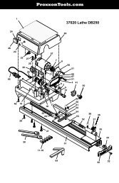
Description of the machine<br />
You will find the PROXXON Micro wood turning lathe, <strong>DB</strong><br />
<strong>250</strong> is ideal for turning small workpieces of wood or<br />
similar materials. This lathe is not suitable for working<br />
metals. The basic equipment includes: 6 chucks: 2, 3, 4,<br />
6, 8 and 10 mm (.07, .11, .15, .23, .31, .39 in.), 2 chuck<br />
keys, 1 lathe centre, 1 drive spike, 1 workpiece holder<br />
and 1 centring ruler.<br />
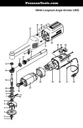
Overall view (Fig. 1):<br />
GROUNDING<br />
PIN<br />
1. On/off switch<br />
2. Speed control<br />
3. Spanner flats<br />
4. Spindle with collet chuck<br />
5. Work piece holder for motor-driven spindle<br />
6. Support<br />
7. Base plate<br />
8. Drive spike<br />
9. Tailstock with tailstock quill.<br />
10. Bed<br />
11. Holes for table fastening<br />
12. Collet chucks<br />
13. Check key<br />
14. Centring ruler<br />
<br />
Installation of the wood turning lathe<br />
Before starting work on the wood turning lathe, use the<br />
wood screws to attach the machine to a stable wooden<br />
board. The wooden board can subsequently be fixed to<br />
the table by means of a vice (Fig. 2).<br />
Operation<br />
Fitting round rods in the collet chuck<br />
The collet chucks supplied can be used to easily clamp<br />
round pieces of wood with the following diameters:<br />
5<br />
/64”, 7 /64”, 5 /32”, 15 /64”, 5 /16” and 13 /32” (2, 3, 4, 6, 8, 10 mm). For<br />
this purpose use the key to block motor-driven spindle 1<br />
(Fig. 3), and unscrew nut 2. Place the requested collet<br />
chuck 3, and slightly attach the nut. Insert work piece 4 in<br />
the collet chuck, and tighten the nut by hand Check for<br />
true running manually. Subsequently, use the second key<br />
to thighten the nut.<br />
Note:<br />
Carefully tension the nut in order to prevent the collet<br />
chuck being damaged!<br />
To this end, please proceed as described in the section<br />
"Clamping of long workpieces" on the next page. Long<br />
work pieces must be provided with additional support on<br />
the tailstock side.<br />
Clamping round wood in the workpiece holder<br />
Clamping round wood that is very thick in relation to its<br />
length:<br />
1. Mark two saw-lines with the centring ruler (fig. 4). Use<br />
a fine saw blade to saw along the lines to a depth of<br />
2 mm.<br />
2. At the point where the two lines cross, bore a hole of<br />
about 2mm dia. and 5 mm depth<br />
3. Position the workpiece on the holder as shown in fig.<br />
5 and scrow it fast.<br />
4. Fix the workpiece with the holder in drive spindle 1,<br />
as described in chapter 1 for the clamping of round<br />
rod.<br />
5. Push tailstock 1 (fig. 6) up to the back end of the<br />
workpiece and clamp it fast to the bed with knurled<br />
nut<br />
6. Turn knurled nut 3 to bring the point into contact with<br />
the workpiece so that it is fixed.<br />
- 6 -
Clamping of long workpieces<br />
(thicker than 10 mm)<br />
1. Insert drive spike 1 (fig. 7) in the drive spindle and<br />
screw it tight (as described in the clamping of round<br />
rod).<br />
2. Push tailstock up to the back end of the workpiece as<br />
shown' in fig. 8 and clamp it fast to the bed with the<br />
knurled nut, exactly as described in the previous<br />
section.<br />
3. Turn the knurled nut to bring the point into contact<br />
with the workpiece so that it is fixed<br />
4. Adjust tool rest 1 so that it is positioned about<br />
2 mm from the workpiece (fig. 9) The holder arm can<br />
be clamped fast in the required position with screw 2.<br />
5. If required, the knurled screw can be loosened in<br />
order to adjust the sideways inclination of the tool<br />
rest.<br />
If plates or similar shapes are to be turned, the work<br />
piece must be screwed down to the holding device (Fig.<br />
5). Ensure that the screws do not protrude from the work<br />
piece after machining.<br />
Risk of injury!<br />
Tip: Particularly short work pieces are fastened by<br />
screwing an intermediate plate to the holding device (as<br />
described above), and attaching the work piece to the<br />
intermediate plate with double sided adhesive tape.<br />
Longitudinal turning<br />
Note!<br />
Prior to turning, always remove centring key 2<br />
(Fig. 4).<br />
1. Check the work piece for true running by turning<br />
manually.<br />
2. Set support 1 (Fig. 9) so that the space is about 2 mm<br />
(.07 in.).<br />
3. Tighten screw 2.<br />
4. When turning, hold the chisel as shown in Fig. 9.<br />
Maintenance<br />
Important<br />
Pull out the mains plug prior to commencing all maintenance<br />
and repair work.<br />
Warning!<br />
Turn switch OFF and always remove plug from power<br />
source before making any adjustments or repairs.<br />
If any part is missing or damaged, do not plug the tool in<br />
until the missing or damaged part is replaced, and<br />
assembly is complete. To avoid electrical shock, use only<br />
identical replacement parts when servicing the tool.<br />
Warning!<br />
To avoid fire or toxic reaction, never use gasoline,<br />
naphtha, acetone, lacquer thinner, or similar highly<br />
volatile solvents to clean the Micro wood lathe.<br />
Do not allow brake fluids, gasoline, or penetrating oils to<br />
come in contact with the plastic parts. They contain chemicals<br />
that can damage or destroy plastics!<br />
All electrical or mechanical repairs should be done only<br />
by qualified service technicians.<br />
When servicing use only PROXXON replacement parts.<br />
Use of any other parts may create a hazard or cause product<br />
damage.<br />
Any attempt to repair or replace electrical parts on this<br />
tool may create a hazard unless repair is done by a<br />
qualified service technician.<br />
Repair service is available at your PROXXON service<br />
center<br />
(You find the address at address at the back of this<br />
manual).<br />
Transverse turning<br />
1. Undo screw 1 (Fig. 10) and turn support 2 by 90<br />
degrees. Allow the support to engage in pad 3.<br />
2. Set the distance from the work piece, and tighten<br />
screw 1 again.<br />
Reworking the work piece<br />
After turning the work piece can be ground with a fine abrasive<br />
cloth at medium speed, and coloured designs can<br />
be applied by brush when the machine is operating at<br />
minimum speed.<br />
When grinding, ensure that the abrasive cloth does not<br />
wrap around the workpiece (Fig. 11).<br />
Risk of Injury!<br />
- 7 -