

www . intelligentactuator . de Long Stroke and High-Speed ...
www . intelligentactuator . de Long Stroke and High-Speed ...
www . intelligentactuator . de Long Stroke and High-Speed ...

You also want an ePaper? Increase the reach of your titles
YUMPU automatically turns print PDFs into web optimized ePapers that Google loves.
GB<br />
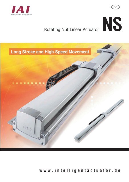
Rotating Nut Linear Actuator<br />
NS<br />
<strong>Long</strong> <strong>Stroke</strong> <strong>and</strong> <strong>High</strong>-<strong>Speed</strong> Movement<br />
w w w . i n t e l l i g e n t a c t u a t o r . d e
Maximum speed 2400 mm/s, maximum<br />
acceleration 1g high-speed performance<br />
A maximum speed of 2400 mm/s is attained through the<br />
use of high-lead precision screws (equivalent to C5). Also,<br />
since there is minimal impact from dangerous rotation<br />
speeds, movement is possible at the maximum 2400<br />
mm/s even at the maximum stroke (3000 mm), so the<br />
cycle time can be greatly reduced.<br />
Maximum speed (m/s)<br />
ISA series<br />
NS series<br />
about 3.5x<br />
high-speed<br />
performance<br />
The intermediate support structure provi<strong>de</strong>s a<br />
long stroke of 3000 mm.<br />
<strong>Stroke</strong> (mm)<br />
The NS series combines nut rotation functions with the<br />
intermediate support structure that has proven itself in<br />
the ISA series to attain a 3000-mm stroke, stunning for a<br />
ball screw machine.<br />
Intermediate<br />
support<br />
Intermediate<br />
support<br />
Multi-sli<strong>de</strong>r support [Equipped with<br />
collision prevention function]<br />
Two sli<strong>de</strong>rs are set on one shaft <strong>and</strong> a multi-sli<strong>de</strong>r is set to operate<br />
them separately. Since this makes it possible for two shafts to<br />
operate in the space of one shaft, it has a great effect in saving<br />
space <strong>and</strong> reducing takt time. The "collision prevention function" to<br />
prevent collisions between the sli<strong>de</strong>rs is st<strong>and</strong>ard equipment.<br />
Length reduced further<br />
Using a built-in nut rotation motor <strong>and</strong> putting the motor<br />
on the outsi<strong>de</strong> of the ball screw eliminates the previous<br />
need for motor installation space <strong>and</strong> links the ball<br />
screw directly to further shorten the length even<br />
compared to the IS series which has already greatly<br />
reduced it.<br />
62 mm shortening<br />
Extension cableveyor option setting<br />
A cableveyor that<br />
exp<strong>and</strong>s the capacity<br />
is available as an<br />
option.<br />
<br />
NS series<br />
IS series<br />
* Compared with 2500mm stroke <strong>and</strong> with<br />
intermediate support<br />
<br />
2
Rotating Nut Linear Actuator that Provi<strong>de</strong>s<br />
<strong>Long</strong> <strong>Stroke</strong> <strong>and</strong> <strong>Speed</strong> Nearly as Fast as Linear<br />
Maximum <strong>Speed</strong> 2400 mm/s, Maximum Acceleration 1G<br />
<strong>High</strong>-<strong>Speed</strong> Performance <strong>and</strong> Multisli<strong>de</strong>r to<br />
Greatly Reduce Cycle Time<br />
Moves the sli<strong>de</strong>r by rotating a nut, not with a ball screw.<br />
The actuator structure is that rather than<br />
moving the nut in the straight line by<br />
rotating a ball screw, the ball screw is fixed<br />
<strong>and</strong> the nut is rotated by a built-in nut rotation<br />
motor built into the sli<strong>de</strong>r, so the sli<strong>de</strong>r moves<br />
in a straight line.<br />
Because the ball screw does not rotate,<br />
the influence of dangerous rotation<br />
speeds is minimal <strong>and</strong> this makes possible<br />
movement at high speed even for long<br />
strokes.<br />
Nut<br />
Ball screw<br />
Motor<br />
Ball screw<br />
ISA series<br />
Built-in nut rotation motor<br />
1<br />
NS series
Mo<strong>de</strong>l<br />
N S 4 0 0 T 2<br />
Series Type Enco<strong>de</strong>r type Motor type Lead <strong>Stroke</strong> Adaptive controller Cable length Options<br />
Absolute<br />
Incremental<br />
Horizontal specifications/<br />
single sli<strong>de</strong>r<br />
Horizontal specifications/<br />
multi-sli<strong>de</strong>r<br />
Horizontal specifications/<br />
single sli<strong>de</strong>r with intermediate<br />
support<br />
Vertical specifications/<br />
single sli<strong>de</strong>r<br />
Vertical specifications/<br />
multi-sli<strong>de</strong>r<br />
No cable<br />
1 m<br />
3 m<br />
5 m<br />
Length specified<br />
Robot cable<br />
Brakes<br />
(only for vertical specifications)<br />
Creep<br />
St<strong>and</strong>ard cableveyor direction 2<br />
St<strong>and</strong>ard cableveyor direction 3<br />
St<strong>and</strong>ard cableveyor direction 4<br />
Extension cableveyor direction 1<br />
Extension cableveyor direction 2<br />
Extension cableveyor direction 3<br />
Extension cableveyor direction 4<br />
Limit switch<br />
Specifications Table<br />
Sli<strong>de</strong>r Appearance Type Enco<strong>de</strong>r type Motor type Lead <strong>Stroke</strong> Rated Maximum Maximum Page<br />
(mm) (mm) thrust (N) transportable speed"<br />
weight (kg) (mm/s)<br />
Horizontal<br />
specifications<br />
Single sli<strong>de</strong>r<br />
LXMS<br />
40<br />
20<br />
500〜1200<br />
170<br />
340.1<br />
40<br />
80<br />
2400<br />
1300<br />
P5<br />
Multi-sli<strong>de</strong>r<br />
LXMM<br />
40<br />
20<br />
250〜2250<br />
170<br />
340.1<br />
40<br />
80<br />
2400<br />
1300<br />
P6<br />
Horizontal<br />
specifications<br />
with intermediate<br />
support<br />
Single sli<strong>de</strong>r<br />
LXMXS<br />
Absolute<br />
Incremental<br />
400<br />
40<br />
20<br />
1300〜3000<br />
170<br />
340.1<br />
40<br />
80<br />
2400<br />
1300<br />
P7<br />
Single sli<strong>de</strong>r<br />
LZMS<br />
500〜1000<br />
P8<br />
Vertical<br />
specifications<br />
20<br />
340.1<br />
16<br />
1000<br />
Multi-sli<strong>de</strong>r<br />
LZMM<br />
250〜950<br />
P9<br />
Table of Transportable Weight By Acceleration Conditions<br />
1. Horizontal installation<br />
Type Motor output Lead Maximum Maximum Transportable weight by acceleration (kg)<br />
(W) (mm) speed" acceleration<br />
(mm/s) (G) 0.3G 0.4G 0.5G 0.6G 0.7G 0.8G 0.9G 1.0G<br />
LXMS<br />
LXMM<br />
40<br />
20<br />
2400<br />
1300<br />
1.0<br />
1.0<br />
40<br />
80<br />
30<br />
60<br />
25<br />
48<br />
20<br />
40<br />
17<br />
34<br />
15<br />
30<br />
13<br />
27<br />
10<br />
24<br />
400<br />
LXMXS<br />
40 2400<br />
40 — — — — — — —<br />
0.3<br />
20 1300<br />
80 — — — — — — —<br />
2. Vertical installation<br />
Type Motor output Lead Maximum Maximum Transportable weight by acceleration (kg)<br />
(W) (mm) speed" acceleration<br />
(mm/s) (G) 0.3G 0.4G 0.5G 0.6G 0.7G 0.8G 0.9G 1.0G<br />
3<br />
LZMS<br />
LZMM<br />
400 20 1000 0.8 16 12.3 11.1 10.1 9.2 6 — —
4<br />
Explanation of main unit options<br />
Brakes<br />
Mo<strong>de</strong>l<br />
B<br />
Explanation<br />
This is a structure that holds the sli<strong>de</strong>r so that if the actuator is used vertically <strong>and</strong> the power is switched Off or the servo goes Off, the sli<strong>de</strong>r does not fall <strong>and</strong> damage<br />
installed items. In the NS series vertical specifications (LZMS/LZMM), brakes are st<strong>and</strong>ard equipment. (Brakes are not set for the horizontal specifications.)<br />
Creep sensor<br />
Mo<strong>de</strong>l<br />
C<br />
Explanation<br />
When the return-to-origin operation is carried out with the incremental specifications, in or<strong>de</strong>r to shorten the return-to-origin time, the sli<strong>de</strong>r is moved at high speed<br />
to just before the position <strong>and</strong> when it passes this sensor, the speed is dropped to resume normal return-to-origin operations. Since this sensor is mounted within the<br />
actuator itself, it does not affect the appearance or external dimensions.<br />
St<strong>and</strong>ard cableveyor installation direction change/extension cableveyor installation<br />
Mo<strong>de</strong>l<br />
CT2 / CT3 / CT4 (st<strong>and</strong>ard cableveyor installation direction)<br />
ET1 / ET2 / ET3 / ET4 (exten<strong>de</strong>d cableveyor installation direction)<br />
Explanation<br />
The cableveyor installation direction can be selected from the following four types (including the st<strong>and</strong>ard installation direction).<br />
[Installation direction]<br />
[Cableveyor internal dimensions]<br />
Installation direction 1 (st<strong>and</strong>ard)<br />
St<strong>and</strong>ard cableveyor: No symbol<br />
Exten<strong>de</strong>d cableveyor: Symbol ET1<br />
Installation direction 2 (st<strong>and</strong>ard; different use)<br />
St<strong>and</strong>ard cableveyor: Symbol CT2<br />
Exten<strong>de</strong>d cableveyor: Symbol ET2<br />
<br />
Installation direction 3 (st<strong>and</strong>ard; reverse origin)<br />
St<strong>and</strong>ard cableveyor: Symbol CT3<br />
Exten<strong>de</strong>d cableveyor: Symbol ET3<br />
Installation direction 4 (CT2, origin reversed)<br />
St<strong>and</strong>ard cableveyor: Symbol CT4<br />
Exten<strong>de</strong>d cableveyor: Symbol ET4<br />
<br />
Origin limit switch<br />
Mo<strong>de</strong>l<br />
L<br />
Explanation<br />
Normal NS series return-to-origin operations use the "push contact technique" in which the origin is reached by bringing the sli<strong>de</strong>r in contact with a stopper, inverting,<br />
then <strong>de</strong>tecting the Z phase. L (origin limit switch) is the option for executing the return-to-origin operation without contact by <strong>de</strong>tecting using a proximity sensor, then<br />
inverting. Since origin limit switch is mounted within the actuator itself, it does not affect the appearance or external dimensions.
NS-LXMS<br />
Single-axis robot nut rotation type Main unit width 145mm 400 W horizontal<br />
specifications/single sli<strong>de</strong>r<br />
Mo<strong>de</strong>l item NS LXMS 400 T2<br />
Series<br />
Type<br />
Enco<strong>de</strong>r type<br />
A : Absolute<br />
I : Incremental<br />
Motor type<br />
400:400W<br />
Lead<br />
40:40mm<br />
20:20mm<br />
<strong>Stroke</strong><br />
500:500mm<br />
〜<br />
1200:1200mm<br />
Adaptive<br />
controller<br />
T2:SCON<br />
SSEL<br />
XSEL-P/Q<br />
Cable length<br />
N :None<br />
S :3m<br />
M:5m<br />
X:Length<br />
specified<br />
Options<br />
See option<br />
table<br />
below<br />
Mo<strong>de</strong>l/specs<br />
Mo<strong>de</strong>l<br />
Enco<strong>de</strong>r type<br />
Motor<br />
output<br />
(W)<br />
Lead<br />
(mm)<br />
<strong>Stroke</strong><br />
(mm)<br />
NS-LXMS- 1 -400-40- 2 -T2- 3 - 4<br />
Absolute<br />
40<br />
400<br />
500〜1200<br />
NS-LXMS- 1 -400-20- 2 -T2- 3 - 4<br />
Incremental<br />
20<br />
* For the mo<strong>de</strong>l types above, 1 is the enco<strong>de</strong>r type, 2 the stroke, 3, the cable length, <strong>and</strong> 4 the options.<br />
<strong>Speed</strong><br />
(mm/s)<br />
2400<br />
1300<br />
Acceleration (*1)<br />
Horizontal (G) Vertical (G)<br />
Rated Maximum<br />
Rated<br />
Maximum<br />
0.3 1.0<br />
Horizontal only<br />
0.3 1.0<br />
Transportable weight (*1, *2)<br />
Horizontal (kg) Vertical (kg)<br />
Rated / Maximum<br />
acceleration<br />
40 10<br />
80 24<br />
Rated / Maximum<br />
acceleration<br />
Horizontal only<br />
Rated thrust<br />
(N)<br />
170<br />
340.1<br />
Options<br />
Name<br />
Creep sensor<br />
St<strong>and</strong>ard cableveyor installation<br />
direction change<br />
Exten<strong>de</strong>d cableveyor<br />
Limit switch<br />
Mo<strong>de</strong>l See Page _ Remarks<br />
C<br />
CT2〜CT4<br />
ET1〜ET4<br />
L<br />
→P4<br />
→P4<br />
→P4<br />
→P4<br />
Common specifications<br />
Drive type<br />
Ball screw ø20 mm Equivalent to C5 form rolled<br />
Position repetition precision Absolute specifications ±0.01 mm/Incremental specifications ± 0.02 mm<br />
Backlash<br />
0.02 mm max.<br />
Gui<strong>de</strong><br />
Base one-piece mo<strong>de</strong>l<br />
Permitted load moment Ma: 104.9N・m Mb: 149.9N・m Mc :248.9N・m<br />
Extension load length Ma direction: 750 mm max. Mb, Mc direction: 750 mm max.<br />
Base<br />
Material: Aluminum, white treated alumite<br />
Cable length (*3)<br />
N: No cable S: 3 m M: 5 m X: Length specified<br />
Usage ambient temperature 0-40˚C, 85% RH max. (no con<strong>de</strong>nsation allowed)<br />
Dimension diagram<br />
CAD drawings can be<br />
downloa<strong>de</strong>d from the homepage<br />
2D<br />
CAD<br />
<br />
<br />
<br />
<br />
<br />
(Reamer pitch)<br />
2-ø 8H7 <strong>de</strong>pth 10<br />
<br />
<br />
<br />
Details D section<br />
Details<br />
Slot <strong>de</strong>pth 10<br />
E section<br />
ø16<br />
ø 9<br />
Base installation<br />
hole section<br />
<br />
Details<br />
<br />
<br />
<br />
<br />
<br />
<br />
<br />
<br />
<br />
<br />
<br />
<br />
<br />
<br />
<br />
<br />
Origin<br />
<br />
<br />
<br />
<br />
8-M8 <strong>de</strong>pth 20<br />
※1 In the return-to-origin,<br />
the sli<strong>de</strong>r moves to the<br />
mechanism end, so watch<br />
out for interference with the<br />
surroundings.<br />
<br />
<br />
<br />
<br />
<br />
<br />
D section<br />
<br />
<br />
<br />
<br />
2-M5 <strong>de</strong>pth 10<br />
<br />
<br />
<br />
<br />
ø8H7 <strong>de</strong>pth 10<br />
SE:<strong>Stroke</strong> end<br />
ME:Mechanism end<br />
<br />
E section<br />
<br />
C-ø9 through hole, ø16 <strong>de</strong>pth spot face<br />
(from opposite si<strong>de</strong>)<br />
<br />
<br />
<br />
<br />
<br />
<br />
<br />
<br />
<br />
<br />
<br />
<br />
About the number of cables <strong>and</strong> hoses that<br />
can be contained <strong>and</strong> their diameters<br />
1 Make the gap between the cable <strong>and</strong> hose outsi<strong>de</strong> <strong>and</strong> the inner wall <strong>and</strong> the<br />
gap between cables <strong>and</strong> hoses at least 2 mm.<br />
2 Make the cable <strong>and</strong> hose exterior diameter 16.8 or less <strong>and</strong> run cables <strong>and</strong><br />
hoses in parallel, not crossing each other.<br />
3 Be careful. If more cables <strong>and</strong> hoses are put into a cableveyor than the specifications<br />
allow, this imposes excess force on the cables <strong>and</strong> drastically shortens<br />
their service life.<br />
<strong>Stroke</strong> 500 600 700 800 900 1000 1100 1200<br />
L<br />
A<br />
B<br />
C<br />
Weight (kg)<br />
828<br />
1<br />
138<br />
10<br />
18.6<br />
928<br />
1<br />
188<br />
10<br />
20.1<br />
1028<br />
1<br />
238<br />
10<br />
21.6<br />
1128<br />
1<br />
288<br />
10<br />
23.1<br />
1228<br />
2<br />
138<br />
14<br />
24.5<br />
1328<br />
2<br />
188<br />
14<br />
26.0<br />
1428<br />
2<br />
238<br />
14<br />
27.5<br />
1528<br />
2<br />
288<br />
14<br />
29.0<br />
Adaptive controller specifications<br />
5<br />
Adaptive<br />
controller<br />
X-SEL-P/Q<br />
SSEL<br />
SCON<br />
Maximum<br />
number of<br />
axes controlled<br />
6 axes<br />
2 axes<br />
1axis<br />
Connectable<br />
enco<strong>de</strong>r types<br />
Absolute/<br />
incremental<br />
Operation<br />
method<br />
Program<br />
Positioner pulse<br />
string control<br />
Power supply<br />
voltage<br />
Three phase/<br />
single phase<br />
200 VAC<br />
Single phase<br />
100/200 VAC<br />
Notes<br />
Note 1: For <strong>de</strong>tails on the relationship between the acceleration <strong>and</strong> the transportable<br />
weight, see Page 3.<br />
Note 2: The transportable weight is the value when operating at the maximum speed.<br />
Note 3: The maximum cable length is 30 m. When specifying the length, enter in<br />
meters. (Example: X08=8 m)
NS-LXMM<br />
Single-axis robot nut rotation type Main unit width 145mm 400 W<br />
Horizontal specifications/multi-sli<strong>de</strong>r<br />
Mo<strong>de</strong>l item NS LXMM 400 T2<br />
Series<br />
Type<br />
Enco<strong>de</strong>r type<br />
A : Absolute<br />
I : Incremental<br />
Motor type<br />
400:400W<br />
Lead<br />
40:40mm<br />
20:20mm<br />
<strong>Stroke</strong><br />
250:250mm<br />
〜<br />
2250:2250mm<br />
Adaptive<br />
controller<br />
T2:SCON<br />
SSEL<br />
XSEL-P/Q<br />
Cable length<br />
N :None<br />
S :3m<br />
M:5m<br />
X:Length<br />
specified<br />
Options<br />
See option<br />
table<br />
below<br />
Mo<strong>de</strong>l/specs<br />
Mo<strong>de</strong>l<br />
Enco<strong>de</strong>r type<br />
Motor<br />
output<br />
(W)<br />
Lead<br />
(mm)<br />
<strong>Stroke</strong><br />
(mm)<br />
NS-LXMM- 1 -400-40- 2 -T2- 3 - 4<br />
Absolute<br />
40<br />
Incremental 400<br />
250〜2250<br />
NS-LXMM- 1 -400-20- 2 -T2- 3 - 4<br />
20<br />
* For the mo<strong>de</strong>l types above, 1 is the enco<strong>de</strong>r type, 2 the stroke, 3, the cable length, <strong>and</strong> 4 the options.<br />
<strong>Speed</strong><br />
(mm)<br />
2400<br />
1300<br />
Acceleration (*1)<br />
Horizontal (kg) Vertical (kg)<br />
Rated<br />
Maximum<br />
Rated<br />
Maximum<br />
0.3 1.0<br />
Horizontal only<br />
0.3 1.0<br />
Transportable weight (*1, *2)<br />
Horizontal (kg) Vertical (kg)<br />
Rated / Maximum<br />
acceleration<br />
40 10<br />
80 24<br />
Rated / Maximum<br />
acceleration<br />
Horizontal only<br />
Rated thrust<br />
(N)<br />
170<br />
340.1<br />
Options<br />
Name<br />
Creep sensor<br />
Extension cableveyor<br />
Limit switch<br />
Mo<strong>de</strong>l See Page _ Remarks<br />
C<br />
ET1<br />
L<br />
→P4<br />
→P4<br />
→P4<br />
Common specifications<br />
Drive type<br />
Ball screw ø20 mm Equivalent to C5 form rolled<br />
Position repetition precision Absolute specifications ±0.01 mm/Incremental specifications ± 0.02 mm<br />
Backlash<br />
0.02 mm max.<br />
Gui<strong>de</strong><br />
Base one-piece mo<strong>de</strong>l<br />
Permitted load moment Ma:104.9N・m Mb:149.9N・m Mc:248.9N・m<br />
Extension load length Ma direction: 750 mm max. Mb, Mc directions: 750 mm max.<br />
Base<br />
Material: Aluminum, white treated alumite<br />
Cable length (*3)<br />
N: No cable S: 3 m M: 5 m X: Length specified<br />
Usage ambient temperature 0-40˚C, 85% RH max. (no con<strong>de</strong>nsation allowed)<br />
Dimension diagram<br />
CAD drawings can be<br />
downloa<strong>de</strong>d from the homepage<br />
2D<br />
CAD<br />
<br />
<br />
<br />
<br />
(Reamer pitch)<br />
2-ø8 H7 <strong>de</strong>pth 10<br />
<br />
Details<br />
<br />
<br />
<br />
D section<br />
Details<br />
ø 9<br />
Base installation<br />
hole section<br />
Slot <strong>de</strong>pth 10<br />
E section<br />
ø16<br />
<br />
100 (minimum between sli<strong>de</strong>rs) 100 (minimum between sli<strong>de</strong>rs)<br />
<br />
<br />
<br />
Details<br />
<br />
<br />
Origin<br />
<br />
<br />
<br />
<br />
<br />
<br />
<br />
<br />
<br />
<br />
<br />
Origin<br />
<br />
<br />
<br />
8-M8 <strong>de</strong>pth 20<br />
<br />
<br />
In the return-to-origin,<br />
the sli<strong>de</strong>r moves to the<br />
mechanism end, so watch<br />
out for interference with<br />
the surroundings.<br />
<br />
<br />
D section<br />
<br />
<br />
<br />
<br />
<br />
<br />
<br />
M5 <strong>de</strong>pth 10 M5 <strong>de</strong>pth 10<br />
<br />
<br />
<br />
<br />
<br />
ø8 H7 <strong>de</strong>pth 10<br />
SE: <strong>Stroke</strong> end<br />
ME: Mechanism end<br />
<br />
E section<br />
C-ø9 through hole, ø16 <strong>de</strong>pth<br />
spot face<br />
(from opposite si<strong>de</strong>)<br />
<br />
<br />
<br />
<br />
<br />
<br />
<br />
<br />
<br />
<br />
<br />
<br />
<br />
About the number of cables <strong>and</strong> hoses that<br />
can be contained <strong>and</strong> their diameters<br />
1 Make the gap between the cable <strong>and</strong> hose outsi<strong>de</strong> <strong>and</strong> the inner wall <strong>and</strong> the<br />
gap between cables <strong>and</strong> hoses at least 2 mm.<br />
2 Make the cable <strong>and</strong> hose exterior diameter 16.8 or less <strong>and</strong> run cables <strong>and</strong><br />
hoses in parallel, not crossing each other.<br />
3 Be careful. If more cables <strong>and</strong> hoses are put into a cableveyor than the specifications<br />
allow, this imposes excess force on the cables <strong>and</strong> drastically shortens<br />
their service life.<br />
<strong>Stroke</strong><br />
L<br />
A<br />
B<br />
C<br />
828<br />
1<br />
138<br />
10<br />
Weight (kg) 24.7<br />
250 350 450 550 650 750 850 950 1050 1150 1250 1350 1450 1550 1650 1750 1850 1950 2050 2150 2250<br />
928<br />
1<br />
188<br />
10<br />
26.4<br />
1028<br />
1<br />
238<br />
10<br />
28.2<br />
1128<br />
1<br />
288<br />
10<br />
29.9<br />
1228<br />
2<br />
138<br />
14<br />
31.6<br />
1328<br />
2<br />
188<br />
14<br />
33.4<br />
1428<br />
2<br />
238<br />
14<br />
35.1<br />
1528<br />
2<br />
288<br />
14<br />
36.8<br />
1628<br />
3<br />
138<br />
18<br />
38.6<br />
1728<br />
3<br />
188<br />
18<br />
40.3<br />
1828<br />
3<br />
238<br />
18<br />
42<br />
1928<br />
3<br />
288<br />
18<br />
43.8<br />
2028<br />
4<br />
138<br />
22<br />
45.5<br />
2128<br />
4<br />
188<br />
22<br />
47.2<br />
2228<br />
4<br />
238<br />
22<br />
48.9<br />
2328<br />
4<br />
288<br />
22<br />
50.7<br />
2428<br />
5<br />
138<br />
26<br />
52.4<br />
2528<br />
5<br />
188<br />
26<br />
54.1<br />
2628<br />
5<br />
238<br />
26<br />
55.9<br />
2728<br />
5<br />
288<br />
26<br />
57.6<br />
2828<br />
6<br />
138<br />
30<br />
59.3<br />
Adaptive controller specifications<br />
Adaptive<br />
controller<br />
X-SEL-P/Q<br />
SSEL<br />
SCON<br />
Maximum<br />
number of<br />
axes controlled<br />
6 axes<br />
2 axes<br />
1axis<br />
Connectable<br />
enco<strong>de</strong>r types<br />
Absolute/<br />
incremental<br />
Operation<br />
method<br />
Program<br />
Positioner pulse<br />
string control<br />
Power supply<br />
voltage<br />
Three phase/<br />
single 200 VAC<br />
Single phase<br />
100/200 VAC<br />
Notes<br />
Note 1: For <strong>de</strong>tails on the relationship between the acceleration <strong>and</strong> the transportable<br />
weight, see Page 3.<br />
Note 2: The transportable weight is the value when operating at the maximum speed.<br />
Note 3: The maximum cable length is 30 m. When specifying the length, enter in<br />
meters. (Example: X08=8 m)<br />
6
NS-LXMXS<br />
Single-axis robot nut rotation type Main unit width 145mm 400 W<br />
Horizontal specifications, single sli<strong>de</strong>r with intermediate support<br />
Mo<strong>de</strong>l item NS LXMXS 400 T2<br />
Series<br />
Type<br />
Enco<strong>de</strong>r type<br />
A : Absolute<br />
I : Incremental<br />
Motor type<br />
400:400W<br />
Lead<br />
40:40mm<br />
20:20mm<br />
<strong>Stroke</strong><br />
1300:1300mm<br />
〜<br />
3000:3000mm<br />
Adaptive<br />
controller<br />
T2:SCON<br />
SSEL<br />
XSEL-P/Q<br />
Cable length<br />
N :None<br />
S :3m<br />
M:5m<br />
X:Length<br />
specified<br />
Options<br />
See option<br />
table<br />
below<br />
Mo<strong>de</strong>l/specs<br />
Mo<strong>de</strong>l<br />
Enco<strong>de</strong>r type<br />
Motor<br />
output<br />
(W)<br />
Lead<br />
(mm)<br />
<strong>Stroke</strong><br />
(mm)<br />
NS-LXMXS- 1 -400-40- 2 -T2- 3 - 4<br />
40<br />
Horizontal only 400<br />
1300〜3000<br />
NS-LXMXS- 1 -400-20- 2 -T2- 3 - 4<br />
20<br />
* For the mo<strong>de</strong>l types above, 1 is the enco<strong>de</strong>r type, 2 the stroke, 3, the cable length, <strong>and</strong> 4 the options.<br />
<strong>Speed</strong><br />
(mm)<br />
2400<br />
1300<br />
Acceleration (*1) Transportable weight (*1, *2)<br />
Horizontal (kg) Vertical (kg) Horizontal (kg) Vertical (kg)<br />
Rated<br />
Maximumum<br />
acceleration acceleration<br />
Rated<br />
Maxi-<br />
Rated / Maximum Rated / Maximum<br />
0.3<br />
40<br />
Horizontal only<br />
Horizontal only<br />
0.3<br />
80<br />
Rated thrust<br />
(N)<br />
170<br />
340.1<br />
Options<br />
Name<br />
Creep sensor<br />
St<strong>and</strong>ard cableveyor installation<br />
direction change<br />
Exten<strong>de</strong>d cableveyor<br />
Limit switch<br />
C →P4 Remarks<br />
C<br />
CT2〜CT4<br />
ET1〜ET4<br />
L<br />
→P4<br />
→P4<br />
→P4<br />
→P4<br />
Common specifications<br />
Drive type<br />
Ball screw ø20 mm Equivalent to C5 form rolled<br />
Position repetition precision Absolute specifications ±0.01 mm/Incremental specifications ± 0.02 mm<br />
Backlash<br />
0.02 mm max.<br />
Gui<strong>de</strong><br />
Base one-piece mo<strong>de</strong>l<br />
Permitted load moment Ma:104.9N・m Mb:149.9N・m Mc:248.9N・m<br />
Extension load length Ma direction: 750 mm max. Mb, Mc directions: 750 mm max.<br />
Base<br />
Material: Aluminum, white treated alumite<br />
Cable length (*3)<br />
N: No cable S: 3 m M: 5 m X: Length specified<br />
Usage ambient temperature 0-40˚C, 85% RH max. (no con<strong>de</strong>nsation allowed)<br />
Dimension diagram<br />
CAD drawings can be<br />
downloa<strong>de</strong>d from the homepage<br />
2D<br />
CAD<br />
<br />
<br />
<br />
<br />
<br />
(Reamer pitch)<br />
2-ø8 H7 <strong>de</strong>pth 10<br />
Details<br />
Slot <strong>de</strong>pth 10<br />
E section<br />
<br />
<br />
<br />
<br />
<br />
Details D section<br />
ø 16<br />
ø 9<br />
Base installation<br />
hole section<br />
<br />
Details<br />
<br />
<br />
<br />
<br />
<br />
<br />
<br />
<br />
<br />
<br />
<br />
<br />
<br />
<br />
Origin<br />
8-M8 <strong>de</strong>pth 20<br />
<br />
In the return-to-origin,<br />
<br />
the sli<strong>de</strong>r moves to the<br />
<br />
mechanism end, so watch<br />
out for interference with<br />
the surroundings.<br />
<br />
<br />
<br />
<br />
<br />
<br />
D section<br />
E section<br />
<br />
<br />
<br />
<br />
2-M5 <strong>de</strong>pth 10<br />
<br />
<br />
<br />
<br />
2-ø8 H7 <strong>de</strong>pth 10<br />
SE: <strong>Stroke</strong> end<br />
ME: Mechanism end<br />
<br />
<br />
C-ø9 through hole, ø16 <strong>de</strong>pth spot<br />
face (from opposite si<strong>de</strong>)<br />
<br />
<br />
<br />
<br />
<br />
<br />
<br />
<br />
<br />
<br />
<br />
<br />
About the number of cables <strong>and</strong> hoses that<br />
can be contained <strong>and</strong> their diameters<br />
1 Make the gap between the cable <strong>and</strong> hose outsi<strong>de</strong> <strong>and</strong> the inner wall <strong>and</strong><br />
the gap between cables <strong>and</strong> hoses at least 2 mm.<br />
2 Make the cable <strong>and</strong> hose exterior diameter 16.8 or less <strong>and</strong> run cables<br />
<strong>and</strong> hoses in parallel, not crossing each other.<br />
3 Be careful. If more cables <strong>and</strong> hoses are put into a cableveyor than the<br />
specifi cations allow, this imposes excess force on the cables <strong>and</strong> drastically<br />
shortens their service life.<br />
<strong>Stroke</strong> 1300 1400 1500 1600 1700 1800 1900 2000 2100 2200 2300 2400 2500 2600 2700 2800 2900 3000<br />
L<br />
A<br />
B<br />
C<br />
Weight (kg)<br />
1728<br />
3<br />
188<br />
18<br />
31.5<br />
1828<br />
3<br />
238<br />
18<br />
32.9<br />
1928<br />
3<br />
288<br />
18<br />
34.4<br />
2028<br />
4<br />
138<br />
22<br />
35.9<br />
2128<br />
4<br />
188<br />
22<br />
37.4<br />
2228<br />
4<br />
238<br />
22<br />
38.9<br />
2328<br />
4<br />
288<br />
22<br />
40.4<br />
2428<br />
5<br />
138<br />
26<br />
41.9<br />
2528<br />
5<br />
188<br />
26<br />
43.4<br />
2628<br />
5<br />
238<br />
26<br />
44.9<br />
2728<br />
5<br />
288<br />
26<br />
46.4<br />
2828<br />
6<br />
138<br />
30<br />
47.9<br />
2928<br />
6<br />
188<br />
30<br />
49.4<br />
3028<br />
6<br />
238<br />
30<br />
50.9<br />
3128<br />
6<br />
288<br />
30<br />
52.3<br />
3228<br />
7<br />
138<br />
34<br />
53.8<br />
3328<br />
7<br />
188<br />
34<br />
55.3<br />
3428<br />
7<br />
238<br />
34<br />
56.8<br />
Adaptive controller specifications<br />
7<br />
Adaptive<br />
controller<br />
X-SEL-P/Q<br />
SSEL<br />
SCON<br />
Maximum<br />
number of<br />
axes controlled<br />
6 axes<br />
2 axes<br />
1 axis<br />
Connectable<br />
enco<strong>de</strong>r types<br />
Absolute/<br />
incremental<br />
Operation<br />
method<br />
Program<br />
Positioner pulse<br />
string control<br />
Power supply<br />
voltage<br />
Three phase/<br />
single phase<br />
200 VAC Notes<br />
Single phase<br />
100/200 VAC<br />
Note 1: The maximum acceleration is 0.3 G.<br />
Note 2: The transportable weight is the value when operating at the maximum speed.<br />
Note 3: The maximum cable length is 30 m. When specifying the length, enter in<br />
meters. (Example: X08=8 m)
NS-LZMS<br />
Single-axis robot nut rotation type Main unit width 145mm 400 W<br />
Vertical specifications, single sli<strong>de</strong>r<br />
Mo<strong>de</strong>l item NS LZMS 400 T2<br />
Series<br />
Type<br />
Enco<strong>de</strong>r type<br />
A : Absolute<br />
I : Incremental<br />
Motor type<br />
400:400W<br />
Lead<br />
40:40mm<br />
<strong>Stroke</strong><br />
500:500mm<br />
〜<br />
1000:1000mm<br />
Adaptive<br />
controller<br />
T2:SCON<br />
SSEL<br />
XSEL-P/Q<br />
Cable length<br />
N :None<br />
S :3m<br />
M:5m<br />
X:Length<br />
specified<br />
Options<br />
See the<br />
option<br />
price table<br />
below.<br />
Mo<strong>de</strong>l/specs<br />
Mo<strong>de</strong>l<br />
NS-LZMS- 1 -400-40- 2 -T2- 3 -B- 4<br />
Enco<strong>de</strong>r type<br />
Absolute<br />
Incremental<br />
Motor<br />
output (W)<br />
400<br />
Lead<br />
(mm)<br />
20<br />
<strong>Stroke</strong> (mm)<br />
Maximum<br />
speed (m/s)<br />
Acceleration (*1)<br />
Horizontal (G) Vertical (G)<br />
Rated<br />
Maximum<br />
Rated<br />
Maximum<br />
Transportable weight (*1, *2)<br />
Horizontal (kg)<br />
Rated / Maximum<br />
acceleration<br />
500〜1000 1000 For vertical only 0.3 0.8 For vertical only<br />
Vertical (G)<br />
Rated / Maximum<br />
acceleration<br />
16 6.0<br />
Rated thrust<br />
(N)<br />
340.1<br />
* For the mo<strong>de</strong>l types above, 1 is the enco<strong>de</strong>r type, 2 the stroke, 3, the cable length, <strong>and</strong> 4 the options.<br />
Options<br />
Name<br />
Brakes<br />
Creep sensor<br />
St<strong>and</strong>ard cableveyor installation<br />
direction change<br />
Exten<strong>de</strong>d cableveyor<br />
Limit switch<br />
Dimension diagram<br />
Mo<strong>de</strong>l See Page _ Remarks<br />
B<br />
C<br />
CT2〜CT4<br />
ET1〜ET4<br />
L<br />
→P4<br />
→P4<br />
→P4<br />
→P4<br />
→P4<br />
St<strong>and</strong>ard equipment<br />
Common specifications<br />
Drive type<br />
Ball screw ø20 mm Equivalent to C5 form rolled<br />
Position repetition precision Absolute specifications ±0.01 mm/Incremental specifications ± 0.02 mm<br />
Backlash<br />
0.02 mm max.<br />
Gui<strong>de</strong><br />
Base one-piece mo<strong>de</strong>l<br />
Permitted load moment Ma:104.9N・m Mb:149.9N・m Mc:248.9N・m<br />
Extension load length Ma direction: 750 mm max. Mb, Mc directions: 750 mm max.<br />
Brakes<br />
Non-excitation operation electromagnetic brakes st<strong>and</strong>ard equipment<br />
Base<br />
Material: Aluminum, white treated alumite<br />
Cable length (*3)<br />
N: No cable S: 3 m M: 5 m X: Length specified<br />
Usage ambient temperature 0-40˚C, 85% RH max. (no con<strong>de</strong>nsation allowed)<br />
CAD drawings can be<br />
downloa<strong>de</strong>d from the homepage<br />
2D<br />
CAD<br />
<br />
<br />
<br />
<br />
<br />
(Reamer pitch)<br />
2-ø8 H7 <strong>de</strong>pth 10<br />
<br />
<br />
Details<br />
Slot <strong>de</strong>pth 10<br />
E section<br />
ø16<br />
<br />
<br />
ø 9<br />
Details D section Base installation Details<br />
hole section<br />
<br />
<br />
<br />
<br />
<br />
<br />
<br />
<br />
<br />
<br />
<br />
<br />
<br />
<br />
<br />
<br />
Origin<br />
<br />
<br />
8-M8 <strong>de</strong>pth 20<br />
<br />
<br />
<br />
In the return-to-origin,<br />
the sli<strong>de</strong>r moves to the<br />
mechanism end, so watch<br />
out for interference with<br />
the surroundings.<br />
<br />
<br />
D section<br />
<br />
<br />
<br />
<br />
<br />
<br />
<br />
<br />
2-M5 <strong>de</strong>pth 10<br />
<br />
<br />
<br />
<br />
ø8H7 <strong>de</strong>pth 10<br />
SE: <strong>Stroke</strong> end<br />
ME: Mechanism end<br />
<br />
E section<br />
<br />
C-ø9 through hole, ø16 <strong>de</strong>pth spot face<br />
(from opposite si<strong>de</strong>)<br />
<br />
<br />
<br />
<br />
<br />
<br />
<br />
<br />
<br />
<br />
<br />
<br />
About the number of cables <strong>and</strong> hoses that<br />
can be contained <strong>and</strong> their diameters<br />
1 Make the gap between the cable <strong>and</strong> hose outsi<strong>de</strong> <strong>and</strong> the inner wall <strong>and</strong> the<br />
gap between cables <strong>and</strong> hoses at least 2 mm.<br />
2 Make the cable <strong>and</strong> hose exterior diameter 16.8 or less <strong>and</strong> run cables <strong>and</strong><br />
hoses in parallel, not crossing each other.<br />
3 Be careful. If more cables <strong>and</strong> hoses are put into a cableveyor than the specifications<br />
allow, this imposes excess force on the cables <strong>and</strong> drastically shortens<br />
their service life.<br />
<strong>Stroke</strong> 500 600 700 800 900 1000<br />
L<br />
A<br />
B<br />
C<br />
Weight (kg)<br />
878<br />
1<br />
163<br />
10<br />
19.9<br />
978<br />
1<br />
213<br />
10<br />
21.4<br />
1078<br />
1<br />
263<br />
10<br />
22.9<br />
1178<br />
2<br />
113<br />
14<br />
24.4<br />
1278<br />
2<br />
163<br />
14<br />
25.9<br />
1378<br />
2<br />
213<br />
14<br />
27.4<br />
Adaptive controller specifications<br />
Adaptive<br />
controller<br />
X-SEL-P/Q<br />
SSEL<br />
SCON<br />
Maximum<br />
number of axes<br />
controlled<br />
6 axes<br />
2 axes<br />
1 axis<br />
Connectable<br />
enco<strong>de</strong>r types<br />
Absolute/<br />
incremental<br />
Operation<br />
method<br />
Program<br />
Positioner pulse<br />
string control<br />
Power supply<br />
voltage<br />
Three phase/<br />
single phase<br />
200 VAC<br />
Single phase<br />
100/200 VAC<br />
Notes<br />
Note 1: For <strong>de</strong>tails on the relationship between the acceleration <strong>and</strong> the transportable<br />
weight, see Page 3.<br />
Note 2: The transportable weight is the value when operating at the maximum speed.<br />
Note 3: The maximum cable length is 30 m. When specifying the length, enter in<br />
meters. (Example: X08=8 m)<br />
8
NS-LZMM<br />
Single-axis robot nut rotation type main unit width 145 mm 400 W<br />
Vertical specification multi-sli<strong>de</strong>r<br />
Mo<strong>de</strong>l item NS LZMM 400 T2<br />
Series<br />
Type<br />
Enco<strong>de</strong>r type<br />
A : Absolute<br />
I : Incremental<br />
Motor type<br />
400:400W<br />
Lead<br />
20:20mm<br />
<strong>Stroke</strong><br />
250:250mm<br />
〜<br />
950:950mm<br />
Adaptive<br />
controller<br />
T2:SCON<br />
SSEL<br />
XSEL-P/Q<br />
Cable length<br />
N :None<br />
S :3m<br />
M:5m<br />
X:Length<br />
specified<br />
Options<br />
Option<br />
table<br />
below<br />
Reference<br />
Mo<strong>de</strong>l/specs<br />
Mo<strong>de</strong>l<br />
NS-LZMM- 1 -400-20- 2 -T2- 3 -B- 4<br />
Enco<strong>de</strong>r type<br />
Absolute<br />
Incremental<br />
Motor<br />
output<br />
(W)<br />
400<br />
Lead<br />
(mm)<br />
20<br />
<strong>Stroke</strong><br />
(mm)<br />
<strong>Speed</strong><br />
(mm/s)<br />
Acceleration (*1)<br />
Horizontal (G) Vertical (G)<br />
Ratings<br />
Maximum<br />
Ratings<br />
Maximum<br />
Transportable weight (*1, *2)<br />
Horizontal (G)<br />
250〜950 1000 Vertical only 0.3 0.8 Vertical only<br />
Vertical (G)<br />
Ratings / Maximum Ratings / Maximum<br />
acceleration acceleration<br />
16 6.0<br />
Rated<br />
propulsion<br />
340.1<br />
* For the mo<strong>de</strong>l type above, 1 is the enco<strong>de</strong>r type, 2 the stroke, 3, the cable length, <strong>and</strong> 4 the options.<br />
Options<br />
Common specifications<br />
Name<br />
Brakes<br />
Creep sensor<br />
Exten<strong>de</strong>d cable pair<br />
Limit switch<br />
Mo<strong>de</strong>l<br />
B<br />
C<br />
ET1<br />
L<br />
Reference<br />
page<br />
→P4<br />
→P4<br />
→P4<br />
→P4<br />
Remarks<br />
St<strong>and</strong>ard equipment<br />
Drive type<br />
Ball screw ø20 mm Equivalent to C5 form rolled<br />
Positioning repeatability<br />
precision<br />
Absolute specifications ±0.01 mm/Incremental specifications ± 0.02 mm<br />
Backlash<br />
0.02 mm max.<br />
Gui<strong>de</strong><br />
Base one-piece mo<strong>de</strong>l<br />
Permitted load moment Ma:104.9N・m Mb:149.9N・m Mc:248.9N・m<br />
Exten<strong>de</strong>d load length Ma direction: 750 mm max. Mb, Mc direction: 750 mm max.<br />
Brakes<br />
Non-excitation operating electromagnetic brakes st<strong>and</strong>ard<br />
Base<br />
Material: Aluminum, white treated alumite<br />
Cable length (*3) N: No cable S: 3 m M: 5 m X: Length specified<br />
Usage temperature 0-40˚C, 85% RH max. (no con<strong>de</strong>nsation allowed)<br />
Dimensional diagam<br />
CAD drawings can be<br />
downloa<strong>de</strong>d from the home page.<br />
2D<br />
CAD<br />
<br />
<br />
<br />
<br />
<br />
(Reamer pitch)<br />
2-ø8 H7 <strong>de</strong>pth 10<br />
Details<br />
Slot <strong>de</strong>pth 10<br />
E section<br />
ø16<br />
<br />
<br />
<br />
<br />
<br />
<br />
ø 9<br />
Details D section Base installation<br />
hole section <strong>de</strong>tails<br />
100 (minimum between sli<strong>de</strong>rs)<br />
<br />
<br />
<br />
<br />
Origin<br />
<br />
100 (minimum between sli<strong>de</strong>rs)<br />
<br />
<br />
<br />
<br />
<br />
<br />
<br />
<br />
<br />
<br />
<br />
Origin<br />
<br />
<br />
8-M8 <strong>de</strong>pth 20<br />
When returning to the<br />
<br />
<br />
origin, the sli<strong>de</strong>r moves<br />
to the mechanical end, so<br />
watch out for interference<br />
around there.<br />
<br />
<br />
D section<br />
<br />
<br />
<br />
<br />
E section<br />
<br />
<br />
<br />
<br />
M5 <strong>de</strong>pth 10 M5 <strong>de</strong>pth 10<br />
<br />
<br />
<br />
<br />
ø8 H7 <strong>de</strong>pth 10<br />
SE: <strong>Stroke</strong> end<br />
ME: Mechanical end<br />
<br />
C –ø9 through hole, ø16 <strong>de</strong>pth<br />
spot face (from opposite si<strong>de</strong>)<br />
<br />
<br />
<br />
<br />
<br />
<br />
<br />
<br />
<br />
<br />
<br />
<br />
<br />
About the number <strong>and</strong> diameters of cables<br />
<strong>and</strong> hoses stored<br />
1 Set the gaps between the outsi<strong>de</strong> of cable <strong>and</strong> hoses <strong>and</strong> the inner walls <strong>and</strong><br />
between cable hoses themselves to 2 mm min.<br />
2 Make cable <strong>and</strong> hose diameters 16.8 max. <strong>and</strong> use them running in parallel to<br />
each other, not crossing over.<br />
3 If more cables <strong>and</strong> hoses are stored than the specifications call for, this will<br />
generate excessive force on them <strong>and</strong> drastically shorten their service life.<br />
<strong>Stroke</strong> 250 350 450 550 650 750 850 950<br />
L<br />
A<br />
B<br />
C<br />
Weight (kg)<br />
928<br />
1<br />
188<br />
10<br />
27.1<br />
1028<br />
1<br />
238<br />
10<br />
28.8<br />
1128<br />
1<br />
288<br />
10<br />
30.5<br />
1228<br />
2<br />
138<br />
14<br />
32.2<br />
1328<br />
2<br />
188<br />
14<br />
34<br />
1428<br />
2<br />
238<br />
14<br />
35.7<br />
1528<br />
2<br />
288<br />
14<br />
37.4<br />
1628<br />
3<br />
138<br />
18<br />
39.2<br />
Adaptive controller specifications<br />
9<br />
Adaptive<br />
controller<br />
X-SEL-P/Q<br />
SSEL<br />
SCON<br />
Maximum<br />
number of axes<br />
controlled<br />
6 axes<br />
2 axes<br />
1axis<br />
Connectable<br />
enco<strong>de</strong>r types<br />
Absolute/<br />
incremental<br />
Operation<br />
dimensions<br />
Program<br />
Positioner pulse<br />
string control<br />
Power supply<br />
voltage<br />
3-phase/1-<br />
phase, 200<br />
VAC<br />
Single phase<br />
AC, 100/200 V<br />
Notes<br />
Note 1: For the relationship between the acceleration <strong>and</strong> the transportable weight,<br />
see Page 3.<br />
Note 2: The transportable weight is for operation at the maximum speed.<br />
Note 3: The maximum cable length is 30 m. Enter the length specification in meters.<br />
(Example: X08=8 m)
Controller specifications<br />
Controller series type<br />
SCON SSEL<br />
XSEL<br />
P (St<strong>and</strong>ard) Type<br />
Q (Global) Type<br />
General specifications Input/output communications Program Control specifications Basic specifications<br />
Appearance<br />
Power supply capacity<br />
Insulation resistance<br />
Withst<strong>and</strong> voltage<br />
Input power supply<br />
Within operating power supply voltage<br />
Maximum connected total axis<br />
output (W)<br />
Maximum number of axes controlled<br />
Position <strong>de</strong>tection technique<br />
Safety circuit configuration<br />
Drive power cut-off<br />
Enable input<br />
<strong>Speed</strong> setting<br />
Acceleration setting<br />
Operation technique<br />
Program language<br />
Program count<br />
Program step count<br />
Multi-task program count<br />
Position count<br />
Data storage <strong>de</strong>vice<br />
Data input <strong>de</strong>vice<br />
(Option)<br />
St<strong>and</strong>ard I/O<br />
Expan<strong>de</strong>d I/O<br />
Serial communications functions<br />
Other I/O<br />
Field network<br />
Protection functions<br />
Usage ambient temperature <strong>and</strong> humidity<br />
Usage ambient atmosphere<br />
External dimensions<br />
Weight<br />
Accessories<br />
844 VA<br />
Single phase 200 VAC<br />
750W (200V power supply<br />
specifications)<br />
1 axis<br />
Positioner operation<br />
Pulse string control<br />
─<br />
─<br />
─<br />
─<br />
512 max.<br />
EEPROM<br />
Teaching box<br />
Mo<strong>de</strong>ls: RCM-T/TD/E/P<br />
Software for PC<br />
Mo<strong>de</strong>l: RCM-101-MW<br />
(for RS232 communications)<br />
RCM-101-USB<br />
(for USB communications)<br />
16 inputs/16 outputs<br />
(NPN/PMP selectable)<br />
Teaching port (RS485)<br />
System I/O<br />
(Emergency stop input,<br />
brake power supply)<br />
DeviceNet、CC-Link、ProfiBus<br />
72 (W)×200.5(H)×121(D)<br />
1.1kg<br />
I/O flat cable (40 lines)<br />
1660 VA max.<br />
(for 400W, 2-axis operation)<br />
500 VDC, 100 MΩ min.<br />
1500 VAC for one minute<br />
400W (100V power supply<br />
specifications) 800W (200V power<br />
supply specifications)<br />
2 axis<br />
Incremental enco<strong>de</strong>r/absolute enco<strong>de</strong>r<br />
Duplex not possible<br />
Duplex not possible<br />
Internal relay cut-off<br />
Internal relay cut-off<br />
B contact input<br />
B contact input<br />
(Internal power feed type)<br />
(internal power feed type)<br />
1 mm/s – upper limit, which <strong>de</strong>pends on the actuator<br />
0.01 G 1 – upper limit, which <strong>de</strong>pends on the actuator<br />
Not possible<br />
Single phase 100 VAC<br />
Single phase 200 VAC<br />
Program operation<br />
Positioner operation<br />
(Switchable)<br />
2000<br />
8<br />
1500<br />
Flash ROM<br />
(Optional SRAM<br />
battery backup)<br />
Teaching box<br />
Mo<strong>de</strong>ls: IA-T-X-J, IA-T-XD-J<br />
Software for PC<br />
Mo<strong>de</strong>l: IA-101-X-MW-J<br />
(for RS232 communications)<br />
IA-101-USB<br />
(for USB communications)<br />
24 inputs/8 outputs<br />
(NPN/PMP selectable)<br />
Teaching port (RS232C)<br />
USB connector<br />
System I/O<br />
(Emergency stop input,<br />
brake power supply)<br />
(Future support planned)<br />
1.4kg<br />
I/O flat cable (34 lines)<br />
Super SEL language<br />
64<br />
Teaching box<br />
Mo<strong>de</strong>ls: IA-T-X, IA-T-XD<br />
Software for PC<br />
Mo<strong>de</strong>l: IA-101-X-MW<br />
(for RS232 communications)<br />
IA-101-X-USB<br />
(for USB communications)<br />
2400W (for three-phase power)<br />
1600W (for single-phase power)<br />
6 axis<br />
Duplexing possible<br />
External safety circuit<br />
B contact input<br />
(External power feed type, duplex)<br />
Program operation only<br />
6000<br />
16<br />
4000<br />
Flash ROM + SRAM battery backup<br />
32 inputs/16 outputs<br />
(NPN/PMP selectable)<br />
192 inputs max./192 outputs max.<br />
Teaching port (RS232C)<br />
2ch RS232C port<br />
Teaching box<br />
Mo<strong>de</strong>l: IA-T-XA<br />
Software for PC<br />
Mo<strong>de</strong>l: IA-101-XA-MW<br />
(for RS232 communications)<br />
Safety category support<br />
with cable)<br />
System I/O<br />
(Emergency stop input, enable input, ready output)<br />
DeviceNet、CC-Link、ProfiBus、Ethrnet<br />
Motor overcurrent, motor driver temperature check, overload check, enco<strong>de</strong>r open line check,<br />
software limit over, system abnormality, battery abnormality, other<br />
0-40˚C, 10-95% (no con<strong>de</strong>nsation allowed)<br />
There must be no corrosive gas <strong>and</strong> dust must not be particularly bad.<br />
100 (W) x 202.6 (H) x 126 (D)<br />
When absolute battery mounted<br />
±10%<br />
4998 VA max.<br />
(for 2400W, 6-axis operation)<br />
500 VDC, 10 MΩ min.<br />
2500 VAC for one minute<br />
1500 VAC for one minute<br />
Three-phase 200 VAC<br />
Single phase 200 VAC<br />
340 (W) x 195 (H) x 125.3 (D)<br />
(For 6-axis absolute specifications)<br />
5.7 kg (for 6-axis absolute specifications)<br />
I/O flat cable (50 lines)<br />
10
NS Series, Flyer No. 0607-E, Version CJ0108-1A<br />
Motor cable (for XSEL-KE/KT/P/Q, SSEL, SCON) *<br />
Mo<strong>de</strong>l CB-X-MA/CB-XEU-MA<br />
(“EU”: Cable option,<br />
see fig. down)<br />
Enter the cable length (L) at . Up to 30 meters is<br />
supported. Example: 080=8 m<br />
(Front diagram)<br />
Controller si<strong>de</strong><br />
Machine si<strong>de</strong> (Front diagram) 0.75sq<br />
Red U 2<br />
White V 3<br />
Wire Color Signal No.<br />
Green PE 1<br />
Black W 4<br />
No. Signal Color Wire<br />
1<br />
2<br />
3<br />
4<br />
U<br />
V<br />
W<br />
PE<br />
Red<br />
White<br />
Black<br />
Green<br />
0.75sq<br />
(press fit)<br />
Enco<strong>de</strong>r cable (for XSEL-P/Q, SSEL, SCON)<br />
Mo<strong>de</strong>l CB-X2-PA/CB-X2EU-PA<br />
(Front diagram)<br />
Controller si<strong>de</strong><br />
Machine si<strong>de</strong><br />
(Front diagram)<br />
Enco<strong>de</strong>r cable (for XSEL-P/Q, SSEL, SCON, specifications with limit switch)<br />
Mo<strong>de</strong>l CB-X2-PLA/CB-X2EU-PLA<br />
Controller si<strong>de</strong><br />
LS<br />
Machine si<strong>de</strong><br />
(Front diagram)<br />
(“EU”: Cable option,<br />
see fig. down)<br />
Enter the cable length (L) at . Up to 30 meters is<br />
supported. Example: 080=8 m<br />
Wire Color Signal No.<br />
White/blue<br />
10<br />
11<br />
12<br />
13<br />
26<br />
25<br />
24<br />
23<br />
9<br />
18<br />
19<br />
1<br />
AWG26 White/yellow<br />
2<br />
(sol<strong>de</strong>red) White/red<br />
3<br />
White/black<br />
4<br />
White/purple<br />
5<br />
White/gray<br />
6<br />
Orange<br />
7<br />
Green<br />
8<br />
Purple<br />
14<br />
Gray<br />
15<br />
Red<br />
16<br />
Black<br />
17<br />
Blue<br />
20<br />
Yellow<br />
21<br />
22<br />
The shield is clamped to the hood.<br />
Drain line <strong>and</strong> shield braid<br />
(The wire colors white/blue show the b<strong>and</strong> color/insulation color.)<br />
(“EU”: Cable option,<br />
see fig. down)<br />
Wire Color Signal No.<br />
White/orange<br />
10<br />
11<br />
12<br />
White/green<br />
13<br />
Brown/blue<br />
26<br />
Brown/yellow<br />
25<br />
Brown/red<br />
24<br />
Brown/black<br />
23<br />
White/blue<br />
9<br />
18<br />
19<br />
1<br />
AWG26 White/yellow<br />
2<br />
(sol<strong>de</strong>red) White/red<br />
3<br />
White/black<br />
4<br />
White/purple<br />
5<br />
White/gray<br />
6<br />
Orange<br />
7<br />
Green<br />
8<br />
Purple<br />
14<br />
Gray<br />
15<br />
Red<br />
16<br />
Black<br />
17<br />
Blue<br />
20<br />
Yellow<br />
21<br />
22<br />
The shield is clamped to the hood.<br />
Drain line <strong>and</strong> shield braid<br />
(The wire colors white/blue show the b<strong>and</strong> color/insulation color.)<br />
No. Signal Color Wire<br />
1<br />
White/blue<br />
2<br />
White/yellow<br />
3<br />
White/red<br />
4<br />
5<br />
White/black<br />
White/purple<br />
AWG26<br />
(press fit)<br />
6<br />
White/gray<br />
7<br />
8<br />
9<br />
Drain<br />
10<br />
Orange<br />
11<br />
Green<br />
12<br />
Purple<br />
13<br />
Gray<br />
14<br />
Red<br />
15<br />
Black<br />
16<br />
17<br />
Blue<br />
18<br />
Yellow<br />
Enter the cable length (L) at . Up to 30 meters is<br />
supported. Example: 080=8 m<br />
No. Signal Color Wire<br />
1 E24V White/orange<br />
2 0V White/green<br />
3 LS Brown/blue AWG26<br />
4 CLEEP Brown/black (press fit)<br />
5 OT Brown/red<br />
6 RSV Brown/black<br />
No. Signal Color Wire<br />
White/blue<br />
White/yellow<br />
White/red<br />
1<br />
2<br />
3<br />
4<br />
5<br />
6<br />
7<br />
8<br />
9<br />
10<br />
11<br />
12<br />
13<br />
14<br />
15<br />
16<br />
17<br />
18<br />
White/black<br />
AWG26<br />
White/purple<br />
(press fit)<br />
White/gray<br />
Drain<br />
Orange<br />
Green<br />
Purple<br />
Gray<br />
Red<br />
Black<br />
Blue<br />
Yellow<br />
* Motor Cable suitable for all Controllers:<br />
[XSEL] [SSEL] [SCON]<br />
Option EU (European St<strong>and</strong>ard)<br />
IAI America Inc.<br />
American Headquarters<br />
2 6 9 0 W 2 3 7 th Str., Torrance, CA 90505, USA<br />
Phone: +1-310-891-6015 Fax: +1-310-891-0815<br />
IAI Industrieroboter GmbH<br />
European Headquarters<br />
Ober <strong>de</strong>r Röth 4, D-65824 Schwalbach, Germany<br />
Phone: +49-6196-8895-0 Fax: +49-6196-8895-24<br />
<strong>www</strong>.<strong>intelligentactuator</strong>.<strong>de</strong><br />
IAI CORPORATION<br />
Global <strong>and</strong> Asean Headquarters<br />
645-1 Shimizu Hirose, Shizuoka 424-0102, Japan<br />
Phone: +81-543-64-5105 Fax: +81-543-64-5182


