

Download Adept Cobra PLC600 User's Guide - pulsar.com.tr
Download Adept Cobra PLC600 User's Guide - pulsar.com.tr
Download Adept Cobra PLC600 User's Guide - pulsar.com.tr

You also want an ePaper? Increase the reach of your titles
YUMPU automatically turns print PDFs into web optimized ePapers that Google loves.
<s<strong>tr</strong>ong>Adept</s<strong>tr</strong>ong> <s<strong>tr</strong>ong>Cobra</s<strong>tr</strong>ong><br />
<s<strong>tr</strong>ong>PLC600</s<strong>tr</strong>ong>/PLC800 Robot<br />
User’s <s<strong>tr</strong>ong>Guide</s<strong>tr</strong>ong><br />
(includes the <s<strong>tr</strong>ong>Adept</s<strong>tr</strong>ong> PLC server)
<s<strong>tr</strong>ong>Adept</s<strong>tr</strong>ong> <s<strong>tr</strong>ong>Cobra</s<strong>tr</strong>ong><br />
<s<strong>tr</strong>ong>PLC600</s<strong>tr</strong>ong>/PLC800 Robot<br />
User’s <s<strong>tr</strong>ong>Guide</s<strong>tr</strong>ong><br />
(includes the <s<strong>tr</strong>ong>Adept</s<strong>tr</strong>ong> PLC server)<br />
P/N: 04866-000, Rev B<br />
May 2005<br />
This manual must be read by all personnel who install, operate, or maintain <s<strong>tr</strong>ong>Adept</s<strong>tr</strong>ong><br />
systems, or who work within or near the workcell.<br />
3011 Triad Drive • Livermore, CA 94551 • USA • Phone 925.245.3400 • Fax 925.960.0452<br />
Otto-Hahn-S<strong>tr</strong>asse 23 • 44227 Dortmund • Germany • Phone 49.231.75.89.40 • Fax 49.231.75.89.450<br />
41, rue du Saule Trapu • 91882 • Massy • France • Phone 33.1.69.19.16.17 • Fax 33.1.69.32.04.62
The information contained herein is the property of <s<strong>tr</strong>ong>Adept</s<strong>tr</strong>ong> Technology, Inc., and shall not be reproduced<br />
in whole or in part without prior written approval of <s<strong>tr</strong>ong>Adept</s<strong>tr</strong>ong> Technology, Inc. The information herein is subject<br />
to change without notice and should not be cons<strong>tr</strong>ued as a <s<strong>tr</strong>ong>com</s<strong>tr</strong>ong>mitment by <s<strong>tr</strong>ong>Adept</s<strong>tr</strong>ong> Technology, Inc. This<br />
manual is periodically reviewed and revised.<br />
<s<strong>tr</strong>ong>Adept</s<strong>tr</strong>ong> Technology, Inc., assumes no responsibility for any errors or omissions in this document. Critical<br />
evaluation of this manual by the user is wel<s<strong>tr</strong>ong>com</s<strong>tr</strong>ong>ed. Your <s<strong>tr</strong>ong>com</s<strong>tr</strong>ong>ments assist us in preparation of future documentation.<br />
Please email your <s<strong>tr</strong>ong>com</s<strong>tr</strong>ong>ments to: techpubs@adept.<s<strong>tr</strong>ong>com</s<strong>tr</strong>ong>.<br />
Copyright © 2004, 2005 by <s<strong>tr</strong>ong>Adept</s<strong>tr</strong>ong> Technology, Inc. All rights reserved.<br />
The <s<strong>tr</strong>ong>Adept</s<strong>tr</strong>ong> Technology logo, <s<strong>tr</strong>ong>Adept</s<strong>tr</strong>ong>Vision, AIM, Blox, Bloxview, FireBlox, Fireview,<br />
HexaVision, HexSight, Meta Con<strong>tr</strong>ols, MetaCon<strong>tr</strong>ols, Metawire, Soft Machines, and Visual Machines<br />
are registered <strong>tr</strong>ademarks of <s<strong>tr</strong>ong>Adept</s<strong>tr</strong>ong> Technology, Inc.<br />
ActiveV, <s<strong>tr</strong>ong>Adept</s<strong>tr</strong>ong>, <s<strong>tr</strong>ong>Adept</s<strong>tr</strong>ong> 1060, <s<strong>tr</strong>ong>Adept</s<strong>tr</strong>ong> 1060+, <s<strong>tr</strong>ong>Adept</s<strong>tr</strong>ong> 1850, <s<strong>tr</strong>ong>Adept</s<strong>tr</strong>ong> 1850 XP, <s<strong>tr</strong>ong>Adept</s<strong>tr</strong>ong> 540, <s<strong>tr</strong>ong>Adept</s<strong>tr</strong>ong> 560, <s<strong>tr</strong>ong>Adept</s<strong>tr</strong>ong><br />
Award, <s<strong>tr</strong>ong>Adept</s<strong>tr</strong>ong> C40, <s<strong>tr</strong>ong>Adept</s<strong>tr</strong>ong> C60, <s<strong>tr</strong>ong>Adept</s<strong>tr</strong>ong> CC, <s<strong>tr</strong>ong>Adept</s<strong>tr</strong>ong> <s<strong>tr</strong>ong>Cobra</s<strong>tr</strong>ong> 550, <s<strong>tr</strong>ong>Adept</s<strong>tr</strong>ong> <s<strong>tr</strong>ong>Cobra</s<strong>tr</strong>ong> 550 CleanRoom, <s<strong>tr</strong>ong>Adept</s<strong>tr</strong>ong> <s<strong>tr</strong>ong>Cobra</s<strong>tr</strong>ong><br />
600, <s<strong>tr</strong>ong>Adept</s<strong>tr</strong>ong> <s<strong>tr</strong>ong>Cobra</s<strong>tr</strong>ong> 800, <s<strong>tr</strong>ong>Adept</s<strong>tr</strong>ong> <s<strong>tr</strong>ong>Cobra</s<strong>tr</strong>ong> i600, <s<strong>tr</strong>ong>Adept</s<strong>tr</strong>ong> <s<strong>tr</strong>ong>Cobra</s<strong>tr</strong>ong> i800, <s<strong>tr</strong>ong>Adept</s<strong>tr</strong>ong> <s<strong>tr</strong>ong>Cobra</s<strong>tr</strong>ong> PLC server, <s<strong>tr</strong>ong>Adept</s<strong>tr</strong>ong> <s<strong>tr</strong>ong>Cobra</s<strong>tr</strong>ong> <s<strong>tr</strong>ong>PLC600</s<strong>tr</strong>ong>,<br />
<s<strong>tr</strong>ong>Adept</s<strong>tr</strong>ong> <s<strong>tr</strong>ong>Cobra</s<strong>tr</strong>ong> PLC800, <s<strong>tr</strong>ong>Adept</s<strong>tr</strong>ong> <s<strong>tr</strong>ong>Cobra</s<strong>tr</strong>ong> s600, <s<strong>tr</strong>ong>Adept</s<strong>tr</strong>ong> <s<strong>tr</strong>ong>Cobra</s<strong>tr</strong>ong> s800, <s<strong>tr</strong>ong>Adept</s<strong>tr</strong>ong> <s<strong>tr</strong>ong>Cobra</s<strong>tr</strong>ong> Smart600, <s<strong>tr</strong>ong>Adept</s<strong>tr</strong>ong> <s<strong>tr</strong>ong>Cobra</s<strong>tr</strong>ong><br />
Smart800, <s<strong>tr</strong>ong>Adept</s<strong>tr</strong>ong> DeskTop, <s<strong>tr</strong>ong>Adept</s<strong>tr</strong>ong> Digital Workcell, <s<strong>tr</strong>ong>Adept</s<strong>tr</strong>ong> FFE, <s<strong>tr</strong>ong>Adept</s<strong>tr</strong>ong> FlexFeeder 250, <s<strong>tr</strong>ong>Adept</s<strong>tr</strong>ong> IC, <s<strong>tr</strong>ong>Adept</s<strong>tr</strong>ong><br />
Impulse Feeder, <s<strong>tr</strong>ong>Adept</s<strong>tr</strong>ong> LineVision, <s<strong>tr</strong>ong>Adept</s<strong>tr</strong>ong> MC, <s<strong>tr</strong>ong>Adept</s<strong>tr</strong>ong> MV, <s<strong>tr</strong>ong>Adept</s<strong>tr</strong>ong> MV-10, <s<strong>tr</strong>ong>Adept</s<strong>tr</strong>ong> MV-19, <s<strong>tr</strong>ong>Adept</s<strong>tr</strong>ong> MV4,<br />
<s<strong>tr</strong>ong>Adept</s<strong>tr</strong>ong> MV-5, <s<strong>tr</strong>ong>Adept</s<strong>tr</strong>ong> MV-8, <s<strong>tr</strong>ong>Adept</s<strong>tr</strong>ong> NanoBonder EBS, <s<strong>tr</strong>ong>Adept</s<strong>tr</strong>ong> NanoBonder LWS, <s<strong>tr</strong>ong>Adept</s<strong>tr</strong>ong> NanoCell, <s<strong>tr</strong>ong>Adept</s<strong>tr</strong>ong><br />
NanoModules, <s<strong>tr</strong>ong>Adept</s<strong>tr</strong>ong> NanoStage L1P2, <s<strong>tr</strong>ong>Adept</s<strong>tr</strong>ong> NanoStage L3, <s<strong>tr</strong>ong>Adept</s<strong>tr</strong>ong> NanoStage L3P2, <s<strong>tr</strong>ong>Adept</s<strong>tr</strong>ong> OC, <s<strong>tr</strong>ong>Adept</s<strong>tr</strong>ong><br />
sDIO, <s<strong>tr</strong>ong>Adept</s<strong>tr</strong>ong> Servo Kit s100, <s<strong>tr</strong>ong>Adept</s<strong>tr</strong>ong> Servo Kit s200, <s<strong>tr</strong>ong>Adept</s<strong>tr</strong>ong> Servo Kit s400, <s<strong>tr</strong>ong>Adept</s<strong>tr</strong>ong> Servo Kit s750, <s<strong>tr</strong>ong>Adept</s<strong>tr</strong>ong><br />
SmartAmp, <s<strong>tr</strong>ong>Adept</s<strong>tr</strong>ong> SmartAxis, <s<strong>tr</strong>ong>Adept</s<strong>tr</strong>ong> SmartCon<strong>tr</strong>oller CS, <s<strong>tr</strong>ong>Adept</s<strong>tr</strong>ong> SmartCon<strong>tr</strong>oller CX, <s<strong>tr</strong>ong>Adept</s<strong>tr</strong>ong><br />
SmartModule, <s<strong>tr</strong>ong>Adept</s<strong>tr</strong>ong> SmartMotion, <s<strong>tr</strong>ong>Adept</s<strong>tr</strong>ong> SmartServo, <s<strong>tr</strong>ong>Adept</s<strong>tr</strong>ong> sMI6, <s<strong>tr</strong>ong>Adept</s<strong>tr</strong>ong> SMIF-EZ, <s<strong>tr</strong>ong>Adept</s<strong>tr</strong>ong>Align 650,<br />
<s<strong>tr</strong>ong>Adept</s<strong>tr</strong>ong>Atlas, <s<strong>tr</strong>ong>Adept</s<strong>tr</strong>ong>Cartesian, <s<strong>tr</strong>ong>Adept</s<strong>tr</strong>ong>Cast, <s<strong>tr</strong>ong>Adept</s<strong>tr</strong>ong>Force, <s<strong>tr</strong>ong>Adept</s<strong>tr</strong>ong>FTP, <s<strong>tr</strong>ong>Adept</s<strong>tr</strong>ong>GEM, <s<strong>tr</strong>ong>Adept</s<strong>tr</strong>ong>Modules,<br />
<s<strong>tr</strong>ong>Adept</s<strong>tr</strong>ong>Motion, <s<strong>tr</strong>ong>Adept</s<strong>tr</strong>ong>Motion Servo, <s<strong>tr</strong>ong>Adept</s<strong>tr</strong>ong>Motion VME, <s<strong>tr</strong>ong>Adept</s<strong>tr</strong>ong>Net, <s<strong>tr</strong>ong>Adept</s<strong>tr</strong>ong>NFS, <s<strong>tr</strong>ong>Adept</s<strong>tr</strong>ong>One, <s<strong>tr</strong>ong>Adept</s<strong>tr</strong>ong>One-MV,<br />
<s<strong>tr</strong>ong>Adept</s<strong>tr</strong>ong>One-XL, <s<strong>tr</strong>ong>Adept</s<strong>tr</strong>ong>RAPID, <s<strong>tr</strong>ong>Adept</s<strong>tr</strong>ong>Six, <s<strong>tr</strong>ong>Adept</s<strong>tr</strong>ong>Six 300, <s<strong>tr</strong>ong>Adept</s<strong>tr</strong>ong>Six 300 CL, <s<strong>tr</strong>ong>Adept</s<strong>tr</strong>ong>Six 300 CR, <s<strong>tr</strong>ong>Adept</s<strong>tr</strong>ong>Six 600,<br />
<s<strong>tr</strong>ong>Adept</s<strong>tr</strong>ong>TCP/IP, <s<strong>tr</strong>ong>Adept</s<strong>tr</strong>ong>Three, <s<strong>tr</strong>ong>Adept</s<strong>tr</strong>ong>Three-MV, <s<strong>tr</strong>ong>Adept</s<strong>tr</strong>ong>Three-XL, <s<strong>tr</strong>ong>Adept</s<strong>tr</strong>ong>Two, <s<strong>tr</strong>ong>Adept</s<strong>tr</strong>ong>Vicron, <s<strong>tr</strong>ong>Adept</s<strong>tr</strong>ong>Vicron<br />
300S, <s<strong>tr</strong>ong>Adept</s<strong>tr</strong>ong>Vicron 310D, <s<strong>tr</strong>ong>Adept</s<strong>tr</strong>ong>Viper, <s<strong>tr</strong>ong>Adept</s<strong>tr</strong>ong>Vision AVI, <s<strong>tr</strong>ong>Adept</s<strong>tr</strong>ong>Vision AGS, <s<strong>tr</strong>ong>Adept</s<strong>tr</strong>ong>Vision GV, <s<strong>tr</strong>ong>Adept</s<strong>tr</strong>ong>Vision<br />
I, <s<strong>tr</strong>ong>Adept</s<strong>tr</strong>ong>Vision II, <s<strong>tr</strong>ong>Adept</s<strong>tr</strong>ong>Vision VME, <s<strong>tr</strong>ong>Adept</s<strong>tr</strong>ong>Vision VXL, <s<strong>tr</strong>ong>Adept</s<strong>tr</strong>ong>Vision XGS, <s<strong>tr</strong>ong>Adept</s<strong>tr</strong>ong>Vision XGS II,<br />
<s<strong>tr</strong>ong>Adept</s<strong>tr</strong>ong>Windows, <s<strong>tr</strong>ong>Adept</s<strong>tr</strong>ong>Windows Con<strong>tr</strong>oller, <s<strong>tr</strong>ong>Adept</s<strong>tr</strong>ong>Windows DDE, <s<strong>tr</strong>ong>Adept</s<strong>tr</strong>ong>Windows Offline Editor,<br />
<s<strong>tr</strong>ong>Adept</s<strong>tr</strong>ong>Windows PC, AIM Command Server, AIM Dispense, AIM PCB, AIM VisionWare, A-Series,<br />
AutoCal, AutoTune, AutoWidth, CCM, CCMII, CGM, FlexFeedWare, HexSight, HyperDrive, IO Blox, IO<br />
Blox, 88, Microenvironment, MicroV + , MotionWare, ObjectFinder, ObjectFinder 2000, PackOne,<br />
PalletWare, SMIF-C, SMIF-EZ, SMIF-EZX, SMIF-Z, SMIF-ZX, S-Series, Ul<strong>tr</strong>aOne, V, V + , VisionTeach, are<br />
<strong>tr</strong>ademarks of <s<strong>tr</strong>ong>Adept</s<strong>tr</strong>ong> Technology, Inc.<br />
Any <strong>tr</strong>ademarks from other <s<strong>tr</strong>ong>com</s<strong>tr</strong>ong>panies used in this publication<br />
are the property of those respective <s<strong>tr</strong>ong>com</s<strong>tr</strong>ong>panies.<br />
Printed in the United States of America
Table of Contents<br />
1 In<strong>tr</strong>oduction . . . . . . . . . . . . . . . . . . . . . . . . . . . . . . . . . . . . . . . . . . . . . . . 15<br />
1.1 Product Description. . . . . . . . . . . . . . . . . . . . . . . . . . . . . . . . . . . . . . . . . . . . . . . . 15<br />
Customer-Supplied PLC . . . . . . . . . . . . . . . . . . . . . . . . . . . . . . . . . . . . . . . . . 15<br />
DF1 Protocol . . . . . . . . . . . . . . . . . . . . . . . . . . . . . . . . . . . . . . . . . . . . 15<br />
<s<strong>tr</strong>ong>Adept</s<strong>tr</strong>ong> PLC Server. . . . . . . . . . . . . . . . . . . . . . . . . . . . . . . . . . . . . . . . . . . . . . . 15<br />
<s<strong>tr</strong>ong>Adept</s<strong>tr</strong>ong> <s<strong>tr</strong>ong>Cobra</s<strong>tr</strong>ong> PLC Robot. . . . . . . . . . . . . . . . . . . . . . . . . . . . . . . . . . . . . . . . . 16<br />
Software . . . . . . . . . . . . . . . . . . . . . . . . . . . . . . . . . . . . . . . . . . . . . . . . . . . . . . 17<br />
1.2 Installation Overview . . . . . . . . . . . . . . . . . . . . . . . . . . . . . . . . . . . . . . . . . . . . . . 18<br />
1.3 How Can I Get Help? . . . . . . . . . . . . . . . . . . . . . . . . . . . . . . . . . . . . . . . . . . . . . . 19<br />
<s<strong>tr</strong>ong>Adept</s<strong>tr</strong>ong> Document Library . . . . . . . . . . . . . . . . . . . . . . . . . . . . . . . . . . . . . . . . 19<br />
2 Safety . . . . . . . . . . . . . . . . . . . . . . . . . . . . . . . . . . . . . . . . . . . . . . . . . . . . 21<br />
2.1 Warnings, Cautions, and Notes in Manual . . . . . . . . . . . . . . . . . . . . . . . . . . . . . 21<br />
2.2 Warning Labels on the Robot . . . . . . . . . . . . . . . . . . . . . . . . . . . . . . . . . . . . . . . . 22<br />
2.3 Precautions and Required Safeguards . . . . . . . . . . . . . . . . . . . . . . . . . . . . . . . 24<br />
Safety Barriers . . . . . . . . . . . . . . . . . . . . . . . . . . . . . . . . . . . . . . . . . . . . . . . . . . 24<br />
Impact and Trapping Points . . . . . . . . . . . . . . . . . . . . . . . . . . . . . . . . . . . . . 24<br />
Additional Safety Information . . . . . . . . . . . . . . . . . . . . . . . . . . . . . . . . . . . . 25<br />
2.4 Intended Use of the Robots . . . . . . . . . . . . . . . . . . . . . . . . . . . . . . . . . . . . . . . . . 26<br />
2.5 Robot Modifications . . . . . . . . . . . . . . . . . . . . . . . . . . . . . . . . . . . . . . . . . . . . . . . 27<br />
Acceptable Modifications . . . . . . . . . . . . . . . . . . . . . . . . . . . . . . . . . . . . . . . 27<br />
Unacceptable Modifications . . . . . . . . . . . . . . . . . . . . . . . . . . . . . . . . . . . . 27<br />
2.6 Transport . . . . . . . . . . . . . . . . . . . . . . . . . . . . . . . . . . . . . . . . . . . . . . . . . . . . . . . . 28<br />
2.7 Safety Requirements for Additional Equipment . . . . . . . . . . . . . . . . . . . . . . . . . 28<br />
2.8 Sound Emissions . . . . . . . . . . . . . . . . . . . . . . . . . . . . . . . . . . . . . . . . . . . . . . . . . . 28<br />
2.9 Thermal Hazard . . . . . . . . . . . . . . . . . . . . . . . . . . . . . . . . . . . . . . . . . . . . . . . . . . . 29<br />
2.10 Working Areas . . . . . . . . . . . . . . . . . . . . . . . . . . . . . . . . . . . . . . . . . . . . . . . . . . 29<br />
2.11 Qualification of Personnel . . . . . . . . . . . . . . . . . . . . . . . . . . . . . . . . . . . . . . . . . 29<br />
2.12 Safety Equipment for Operators . . . . . . . . . . . . . . . . . . . . . . . . . . . . . . . . . . . . 30<br />
2.13 Protection Against Unauthorized Operation. . . . . . . . . . . . . . . . . . . . . . . . . . . 30<br />
2.14 Safety Aspects While Performing Maintenance . . . . . . . . . . . . . . . . . . . . . . . 30<br />
2.15 Risks Due to Incorrect Installation or Operation. . . . . . . . . . . . . . . . . . . . . . . . 31<br />
2.16 What to Do in an Emergency Situation . . . . . . . . . . . . . . . . . . . . . . . . . . . . . . . 31<br />
<s<strong>tr</strong>ong>Adept</s<strong>tr</strong>ong> <s<strong>tr</strong>ong>Cobra</s<strong>tr</strong>ong> <s<strong>tr</strong>ong>PLC600</s<strong>tr</strong>ong>/PLC800 Robot User’s <s<strong>tr</strong>ong>Guide</s<strong>tr</strong>ong>, Rev B 5
Table of Contents<br />
3 Equipment Installation . . . . . . . . . . . . . . . . . . . . . . . . . . . . . . . . . . . . . . . 33<br />
3.1 Unpacking and Inspecting the <s<strong>tr</strong>ong>Adept</s<strong>tr</strong>ong> Equipment . . . . . . . . . . . . . . . . . . . . . . . 33<br />
Before Unpacking . . . . . . . . . . . . . . . . . . . . . . . . . . . . . . . . . . . . . . . . . . . . . . . 33<br />
Upon Unpacking . . . . . . . . . . . . . . . . . . . . . . . . . . . . . . . . . . . . . . . . . . . . . . . . 33<br />
3.2 Transport and Storage . . . . . . . . . . . . . . . . . . . . . . . . . . . . . . . . . . . . . . . . . . . . . . 33<br />
3.3 Repacking for Relocation . . . . . . . . . . . . . . . . . . . . . . . . . . . . . . . . . . . . . . . . . . . 34<br />
3.4 Environmental and Facility Requirements . . . . . . . . . . . . . . . . . . . . . . . . . . . . . 35<br />
3.5 Mounting the Robot . . . . . . . . . . . . . . . . . . . . . . . . . . . . . . . . . . . . . . . . . . . . . . . 36<br />
Mounting Surface . . . . . . . . . . . . . . . . . . . . . . . . . . . . . . . . . . . . . . . . . . . . . . . 36<br />
Robot Mounting Procedure. . . . . . . . . . . . . . . . . . . . . . . . . . . . . . . . . . . . . . . 36<br />
3.6 PLC Server Installation . . . . . . . . . . . . . . . . . . . . . . . . . . . . . . . . . . . . . . . . . . . . . . 38<br />
Unpacking the PLC Server . . . . . . . . . . . . . . . . . . . . . . . . . . . . . . . . . . . . . . . . 38<br />
Repacking for Relocation . . . . . . . . . . . . . . . . . . . . . . . . . . . . . . . . . . . . . . . . 38<br />
Space Around the Chassis. . . . . . . . . . . . . . . . . . . . . . . . . . . . . . . . . . . . . . . . 38<br />
Mounting the PLC Server . . . . . . . . . . . . . . . . . . . . . . . . . . . . . . . . . . . . . . . . . 39<br />
Rack Mounting the PLC Server. . . . . . . . . . . . . . . . . . . . . . . . . . . . . . 39<br />
Panel Mounting the PLC Server . . . . . . . . . . . . . . . . . . . . . . . . . . . . . 40<br />
Table Mounting the PLC Server . . . . . . . . . . . . . . . . . . . . . . . . . . . . . 41<br />
CompactFlash Memory Card . . . . . . . . . . . . . . . . . . . . . . . . . . . . . . . . . . . . . 41<br />
Installing CompactFlash. . . . . . . . . . . . . . . . . . . . . . . . . . . . . . . . . . . . . . . . . . 42<br />
4 Wiring the System . . . . . . . . . . . . . . . . . . . . . . . . . . . . . . . . . . . . . . . . . . . 43<br />
4.1 System Cable Diagram . . . . . . . . . . . . . . . . . . . . . . . . . . . . . . . . . . . . . . . . . . . . 43<br />
4.2 <s<strong>tr</strong>ong>Cobra</s<strong>tr</strong>ong> PLC Robot Interface Panel Connectors . . . . . . . . . . . . . . . . . . . . . . . . . . 44<br />
4.3 PLC Server Connectors and Indicators . . . . . . . . . . . . . . . . . . . . . . . . . . . . . . . . 45<br />
4.4 Cable Connections from Robot to PLC Server . . . . . . . . . . . . . . . . . . . . . . . . . . 48<br />
4.5 Cable Connections from the PLC to PLC Server . . . . . . . . . . . . . . . . . . . . . . . . . 48<br />
4.6 Connecting 24 VDC Power to Robot . . . . . . . . . . . . . . . . . . . . . . . . . . . . . . . . . . 49<br />
Specifications for 24 VDC Power . . . . . . . . . . . . . . . . . . . . . . . . . . . . . . . . . . 49<br />
Details for 24 VDC Mating Connector . . . . . . . . . . . . . . . . . . . . . . . . . . . . . . 49<br />
Procedure for Creating 24 VDC Cable . . . . . . . . . . . . . . . . . . . . . . . . . . . . . 51<br />
Installing 24 VDC Robot Cable . . . . . . . . . . . . . . . . . . . . . . . . . . . . . . . . . . . . 51<br />
4.7 Connecting 200-240 VAC Power to Robot . . . . . . . . . . . . . . . . . . . . . . . . . . . . . 52<br />
Specifications for AC Power . . . . . . . . . . . . . . . . . . . . . . . . . . . . . . . . . . . . . . 52<br />
Facility Overvoltage Protection . . . . . . . . . . . . . . . . . . . . . . . . . . . . . 52<br />
AC Power Diagrams . . . . . . . . . . . . . . . . . . . . . . . . . . . . . . . . . . . . . . 53<br />
Details for AC Mating Connector . . . . . . . . . . . . . . . . . . . . . . . . . . . . . . . . . . 54<br />
Procedure for Creating 200-240 VAC Cable . . . . . . . . . . . . . . . . . . . . . . . . 54<br />
Installing AC Power Cable to Robot . . . . . . . . . . . . . . . . . . . . . . . . . . . . . . . 55<br />
4.8 Connecting 24 VDC Power to the PLC Server . . . . . . . . . . . . . . . . . . . . . . . . . . . 55<br />
24 VDC Power Specifications . . . . . . . . . . . . . . . . . . . . . . . . . . . . . . . . . . . . . 55<br />
6 <s<strong>tr</strong>ong>Adept</s<strong>tr</strong>ong> <s<strong>tr</strong>ong>Cobra</s<strong>tr</strong>ong> <s<strong>tr</strong>ong>PLC600</s<strong>tr</strong>ong>/PLC800 Robot User’s <s<strong>tr</strong>ong>Guide</s<strong>tr</strong>ong>, Rev B
Table of Contents<br />
24 VDC Power Cabling . . . . . . . . . . . . . . . . . . . . . . . . . . . . . . . . . . . . . . . . . . 56<br />
Daisy-Chaining Power . . . . . . . . . . . . . . . . . . . . . . . . . . . . . . . . . . . . 56<br />
Installing 24 VDC Connectors . . . . . . . . . . . . . . . . . . . . . . . . . . . . . . 56<br />
4.9 Grounding the <s<strong>tr</strong>ong>Adept</s<strong>tr</strong>ong> Robot System . . . . . . . . . . . . . . . . . . . . . . . . . . . . . . . . . 57<br />
Ground Point on Robot Base . . . . . . . . . . . . . . . . . . . . . . . . . . . . . . . . . . . . . 57<br />
Ground Point on AIB . . . . . . . . . . . . . . . . . . . . . . . . . . . . . . . . . . . . . . . . . . . . 58<br />
PLC Server Grounding . . . . . . . . . . . . . . . . . . . . . . . . . . . . . . . . . . . . . . . . . . . 58<br />
Robot-Mounted Equipment Grounding . . . . . . . . . . . . . . . . . . . . . . . . . . . . 59<br />
4.10 Connecting Customer-Supplied Safety and Power Con<strong>tr</strong>ol Equipment . . . . 59<br />
Connecting Equipment to the System . . . . . . . . . . . . . . . . . . . . . . . . . . . . . 60<br />
Emergency Stop Circuits . . . . . . . . . . . . . . . . . . . . . . . . . . . . . . . . . . . . . . . . . 63<br />
User E-Stop Indication - Remote Sensing of E-Stop . . . . . . . . . . . . . 64<br />
Line E-Stop Input . . . . . . . . . . . . . . . . . . . . . . . . . . . . . . . . . . . . . . . . . 64<br />
Muted Safety Gate E-Stop Circui<strong>tr</strong>y . . . . . . . . . . . . . . . . . . . . . . . . . 64<br />
Remote Manual Mode . . . . . . . . . . . . . . . . . . . . . . . . . . . . . . . . . . . . . . . . . . 65<br />
User Manual/Auto Indication . . . . . . . . . . . . . . . . . . . . . . . . . . . . . . . . . . . . . 65<br />
User High Power On Indication. . . . . . . . . . . . . . . . . . . . . . . . . . . . . . . . . . . . 65<br />
High Power On/Off Lamp . . . . . . . . . . . . . . . . . . . . . . . . . . . . . . . . . . . . . . . . 65<br />
4.11 Connecting Customer-Supplied Digital I/O Equipment . . . . . . . . . . . . . . . . . 66<br />
XDIO Connector. . . . . . . . . . . . . . . . . . . . . . . . . . . . . . . . . . . . . . . . . . . . . . . . 66<br />
Input Signals. . . . . . . . . . . . . . . . . . . . . . . . . . . . . . . . . . . . . . . . . . . . . 66<br />
Output Signals . . . . . . . . . . . . . . . . . . . . . . . . . . . . . . . . . . . . . . . . . . . 67<br />
5 System Operation . . . . . . . . . . . . . . . . . . . . . . . . . . . . . . . . . . . . . . . . . . 71<br />
5.1 Robot Status LED Description . . . . . . . . . . . . . . . . . . . . . . . . . . . . . . . . . . . . . . . . 71<br />
5.2 Status Panel Codes . . . . . . . . . . . . . . . . . . . . . . . . . . . . . . . . . . . . . . . . . . . . . . . . 72<br />
5.3 Using the Brake Release Button . . . . . . . . . . . . . . . . . . . . . . . . . . . . . . . . . . . . . . 73<br />
Brakes . . . . . . . . . . . . . . . . . . . . . . . . . . . . . . . . . . . . . . . . . . . . . . . . . . . . . . . . 73<br />
Brake Release Button. . . . . . . . . . . . . . . . . . . . . . . . . . . . . . . . . . . . . . . . . . . . 73<br />
5.4 Commissioning the System . . . . . . . . . . . . . . . . . . . . . . . . . . . . . . . . . . . . . . . . . 73<br />
Verifying Installation . . . . . . . . . . . . . . . . . . . . . . . . . . . . . . . . . . . . . . . . . . . . . 74<br />
Mechanical Checks . . . . . . . . . . . . . . . . . . . . . . . . . . . . . . . . . . . . . . 74<br />
System Cable Checks . . . . . . . . . . . . . . . . . . . . . . . . . . . . . . . . . . . . 74<br />
User-Supplied Safety Equipment Checks . . . . . . . . . . . . . . . . . . . . . 74<br />
System Start-up Procedure . . . . . . . . . . . . . . . . . . . . . . . . . . . . . . . . . . . . . . . 75<br />
Verifying E-Stop Functions . . . . . . . . . . . . . . . . . . . . . . . . . . . . . . . . . . . . . . . . 75<br />
6 Programming the Robot . . . . . . . . . . . . . . . . . . . . . . . . . . . . . . . . . . . . . 77<br />
6.1 PLC Server Software Overview. . . . . . . . . . . . . . . . . . . . . . . . . . . . . . . . . . . . . . . 77<br />
6.2 Initializing a System. . . . . . . . . . . . . . . . . . . . . . . . . . . . . . . . . . . . . . . . . . . . . . . . 77<br />
6.3 PLC Software Overview. . . . . . . . . . . . . . . . . . . . . . . . . . . . . . . . . . . . . . . . . . . . . 80<br />
Command Registers . . . . . . . . . . . . . . . . . . . . . . . . . . . . . . . . . . . . . . . . . . . . 81<br />
<s<strong>tr</strong>ong>Adept</s<strong>tr</strong>ong> <s<strong>tr</strong>ong>Cobra</s<strong>tr</strong>ong> <s<strong>tr</strong>ong>PLC600</s<strong>tr</strong>ong>/PLC800 Robot User’s <s<strong>tr</strong>ong>Guide</s<strong>tr</strong>ong>, Rev B 7
Table of Contents<br />
Ins<strong>tr</strong>uction Command Register. . . . . . . . . . . . . . . . . . . . . . . . . . . . . . 85<br />
Output Signals Command Register . . . . . . . . . . . . . . . . . . . . . . . . . . 86<br />
Jog Mode Command Register . . . . . . . . . . . . . . . . . . . . . . . . . . . . . 87<br />
Motion Qualifier Command Register. . . . . . . . . . . . . . . . . . . . . . . . . 88<br />
Status Registers . . . . . . . . . . . . . . . . . . . . . . . . . . . . . . . . . . . . . . . . . . . . . . . . . 90<br />
Status Word Bit Definitions . . . . . . . . . . . . . . . . . . . . . . . . . . . . . . . . . . 91<br />
Input Word Bit Definitions . . . . . . . . . . . . . . . . . . . . . . . . . . . . . . . . . . 92<br />
Current Motion Counter . . . . . . . . . . . . . . . . . . . . . . . . . . . . . . . . . . . 93<br />
Current Position Array . . . . . . . . . . . . . . . . . . . . . . . . . . . . . . . . . . . . . 93<br />
Error Registers . . . . . . . . . . . . . . . . . . . . . . . . . . . . . . . . . . . . . . . . . . . . 95<br />
Location & Pallet Register Definitions . . . . . . . . . . . . . . . . . . . . . . . . 96<br />
Pallet Registers . . . . . . . . . . . . . . . . . . . . . . . . . . . . . . . . . . . . . . . . . . . 97<br />
7 Optional Robot Equipment Installation . . . . . . . . . . . . . . . . . . . . . . . . 101<br />
7.1 Installing End-Effectors . . . . . . . . . . . . . . . . . . . . . . . . . . . . . . . . . . . . . . . . . . . . 101<br />
7.2 Removing and Installing the User Flange . . . . . . . . . . . . . . . . . . . . . . . . . . . . . 101<br />
Removing the Flange . . . . . . . . . . . . . . . . . . . . . . . . . . . . . . . . . . . . . . . . . . . 101<br />
Installing the Flange . . . . . . . . . . . . . . . . . . . . . . . . . . . . . . . . . . . . . . . . . . . . 102<br />
7.3 User Connections on Robot . . . . . . . . . . . . . . . . . . . . . . . . . . . . . . . . . . . . . . . . 103<br />
User Air Lines . . . . . . . . . . . . . . . . . . . . . . . . . . . . . . . . . . . . . . . . . . . . . . . . . . 103<br />
User Elec<strong>tr</strong>ical Lines . . . . . . . . . . . . . . . . . . . . . . . . . . . . . . . . . . . . . . . . . . . . . 104<br />
7.4 Internal User Connectors . . . . . . . . . . . . . . . . . . . . . . . . . . . . . . . . . . . . . . . . . . 105<br />
SOLND Connector . . . . . . . . . . . . . . . . . . . . . . . . . . . . . . . . . . . . . . . . . . . . . 106<br />
OP3/4 Connector . . . . . . . . . . . . . . . . . . . . . . . . . . . . . . . . . . . . . . . . . . . . . . 106<br />
EOAPWR Connector . . . . . . . . . . . . . . . . . . . . . . . . . . . . . . . . . . . . . . . . . . . 107<br />
Internal User Connector Output Specifications . . . . . . . . . . . . . . . . . . . . . 108<br />
7.5 Mounting Locations for External Equipment . . . . . . . . . . . . . . . . . . . . . . . . . . . 108<br />
7.6 Installing Robot Solenoid Kit . . . . . . . . . . . . . . . . . . . . . . . . . . . . . . . . . . . . . . . . 109<br />
In<strong>tr</strong>oduction . . . . . . . . . . . . . . . . . . . . . . . . . . . . . . . . . . . . . . . . . . . . . . . . . . . 109<br />
Tools Required . . . . . . . . . . . . . . . . . . . . . . . . . . . . . . . . . . . . . . . . . . . . . . . . . 109<br />
Procedure . . . . . . . . . . . . . . . . . . . . . . . . . . . . . . . . . . . . . . . . . . . . . . . . . . . . 109<br />
7.7 DeviceNet Pass-Through Cable . . . . . . . . . . . . . . . . . . . . . . . . . . . . . . . . . . . . . 113<br />
Re<s<strong>tr</strong>ong>com</s<strong>tr</strong>ong>mended Vendors for Mating Cables and Connectors . . . . . . . . . 113<br />
8 Maintenance . . . . . . . . . . . . . . . . . . . . . . . . . . . . . . . . . . . . . . . . . . . . . 115<br />
8.1 Periodic Maintenance Schedule . . . . . . . . . . . . . . . . . . . . . . . . . . . . . . . . . . . . 115<br />
8.2 Checking of Safety Systems . . . . . . . . . . . . . . . . . . . . . . . . . . . . . . . . . . . . . . . . 116<br />
8.3 Checking Robot Mounting Bolts . . . . . . . . . . . . . . . . . . . . . . . . . . . . . . . . . . . . . 116<br />
8.4 Check Robot for Oil Around Harmonic Drive . . . . . . . . . . . . . . . . . . . . . . . . . . 116<br />
8.5 Lubricate Joint 3 Ball Screw . . . . . . . . . . . . . . . . . . . . . . . . . . . . . . . . . . . . . . . . 117<br />
Required Grease for the Robot. . . . . . . . . . . . . . . . . . . . . . . . . . . . . . . . . . . 117<br />
Lubrication Procedure . . . . . . . . . . . . . . . . . . . . . . . . . . . . . . . . . . . . . . . . . . 117<br />
8 <s<strong>tr</strong>ong>Adept</s<strong>tr</strong>ong> <s<strong>tr</strong>ong>Cobra</s<strong>tr</strong>ong> <s<strong>tr</strong>ong>PLC600</s<strong>tr</strong>ong>/PLC800 Robot User’s <s<strong>tr</strong>ong>Guide</s<strong>tr</strong>ong>, Rev B
Table of Contents<br />
8.6 Replacing the SmartAmp AIB Chassis . . . . . . . . . . . . . . . . . . . . . . . . . . . . . . . 119<br />
Removing the SmartAmp AIB Chassis . . . . . . . . . . . . . . . . . . . . . . . . . . . . . 119<br />
Installing a New SmartAmp AIB Chassis. . . . . . . . . . . . . . . . . . . . . . . . . . . . 121<br />
8.7 Replacing Encoder Battery . . . . . . . . . . . . . . . . . . . . . . . . . . . . . . . . . . . . . . . . 123<br />
Battery Replacement Time Periods . . . . . . . . . . . . . . . . . . . . . . . . . . . . . . . 123<br />
Battery Replacement Procedure. . . . . . . . . . . . . . . . . . . . . . . . . . . . . . . . . 123<br />
8.8 Changing the Lamp in the High Power Indicator. . . . . . . . . . . . . . . . . . . . . . . 124<br />
9 Technical Specifications . . . . . . . . . . . . . . . . . . . . . . . . . . . . . . . . . . . . 127<br />
9.1 Robot Dimension Drawings . . . . . . . . . . . . . . . . . . . . . . . . . . . . . . . . . . . . . . . . 127<br />
9.2 PLC Server Dimensions . . . . . . . . . . . . . . . . . . . . . . . . . . . . . . . . . . . . . . . . . . . . 133<br />
9.3 <s<strong>tr</strong>ong>Adept</s<strong>tr</strong>ong> Front Panel Dimensions . . . . . . . . . . . . . . . . . . . . . . . . . . . . . . . . . . . . . . 134<br />
9.4 Mechanical Specifications . . . . . . . . . . . . . . . . . . . . . . . . . . . . . . . . . . . . . . . . 136<br />
10 Robot Concepts . . . . . . . . . . . . . . . . . . . . . . . . . . . . . . . . . . . . . . . . . 137<br />
10.1 Understanding Robot Motion Parameters. . . . . . . . . . . . . . . . . . . . . . . . . . . . 137<br />
Speed, Acceleration, and Deceleration . . . . . . . . . . . . . . . . . . . . . . . . . . 137<br />
Approach and Depart . . . . . . . . . . . . . . . . . . . . . . . . . . . . . . . . . . . . . . . . . 138<br />
Arm Configuration . . . . . . . . . . . . . . . . . . . . . . . . . . . . . . . . . . . . . . . . . . . . . 138<br />
Continuous-Path Motion . . . . . . . . . . . . . . . . . . . . . . . . . . . . . . . . . . . . . . . . 139<br />
Breaking Continuous-Path Operation . . . . . . . . . . . . . . . . . . . . . . 140<br />
Joint-Interpolated Motion vs. S<strong>tr</strong>aight-Line Motion . . . . . . . . . . . . . . . . . . 140<br />
Performance Considerations . . . . . . . . . . . . . . . . . . . . . . . . . . . . . . . . . . . . 140<br />
Robot Mounting Considerations . . . . . . . . . . . . . . . . . . . . . . . . . . . 140<br />
Cell Layout Considerations . . . . . . . . . . . . . . . . . . . . . . . . . . . . . . . 140<br />
Part Handling Considerations . . . . . . . . . . . . . . . . . . . . . . . . . . . . . 141<br />
Programming Considerations . . . . . . . . . . . . . . . . . . . . . . . . . . . . . 141<br />
10.2 The Coordinate System . . . . . . . . . . . . . . . . . . . . . . . . . . . . . . . . . . . . . . . . . . 142<br />
What is the World Coordinate System?. . . . . . . . . . . . . . . . . . . . . . . . . . . . 142<br />
Defining a Location . . . . . . . . . . . . . . . . . . . . . . . . . . . . . . . . . . . . . 142<br />
10.3 Defining a Pallet Layout . . . . . . . . . . . . . . . . . . . . . . . . . . . . . . . . . . . . . . . . . . 145<br />
Why is Gripper Orientation Important? . . . . . . . . . . . . . . . . . . . . . . . . . . . . 147<br />
11 Diagnostic and Error Messages . . . . . . . . . . . . . . . . . . . . . . . . . . . . 149<br />
11.1 PLC Server Messages . . . . . . . . . . . . . . . . . . . . . . . . . . . . . . . . . . . . . . . . . . . . 149<br />
PLC Server Messages (Numerical Listing) . . . . . . . . . . . . . . . . . . . . . . . . . . 149<br />
PLC Server Messages (Alphabetical Listing) . . . . . . . . . . . . . . . . . . . . . . . . 151<br />
DF1 Protocol — Remote STS Error Codes. . . . . . . . . . . . . . . . . . . . . . . . . . . 154<br />
DF1 Protocol — EXT STS Error Codes . . . . . . . . . . . . . . . . . . . . . . . . . . . . . . . 154<br />
Index . . . . . . . . . . . . . . . . . . . . . . . . . . . . . . . . . . . . . . . . . . . . . . . . . . . . . . . 157<br />
<s<strong>tr</strong>ong>Adept</s<strong>tr</strong>ong> <s<strong>tr</strong>ong>Cobra</s<strong>tr</strong>ong> <s<strong>tr</strong>ong>PLC600</s<strong>tr</strong>ong>/PLC800 Robot User’s <s<strong>tr</strong>ong>Guide</s<strong>tr</strong>ong>, Rev B 9
List of Figures<br />
Figure 1-1. <s<strong>tr</strong>ong>Adept</s<strong>tr</strong>ong> PLC Server . . . . . . . . . . . . . . . . . . . . . . . . . . . . . . . . . . . . . . . . . . . . . . . 16<br />
Figure 1-2. <s<strong>tr</strong>ong>Adept</s<strong>tr</strong>ong> <s<strong>tr</strong>ong>Cobra</s<strong>tr</strong>ong> PLC800 Robot . . . . . . . . . . . . . . . . . . . . . . . . . . . . . . . . . . . . . . 16<br />
Figure 1-3. Robot Joint Motions . . . . . . . . . . . . . . . . . . . . . . . . . . . . . . . . . . . . . . . . . . . . . 17<br />
Figure 2-1. Elec<strong>tr</strong>ical and Thermal Warning Labels on AIB Chassis . . . . . . . . . . . . . . . . . 22<br />
Figure 2-2. Thermal Warning Label on Underside of Inner Link . . . . . . . . . . . . . . . . . . . . 22<br />
Figure 2-3. Warning Label on Encoder Cables . . . . . . . . . . . . . . . . . . . . . . . . . . . . . . . . . 23<br />
Figure 3-1. <s<strong>tr</strong>ong>Cobra</s<strong>tr</strong>ong> <s<strong>tr</strong>ong>PLC600</s<strong>tr</strong>ong>/PLC800 Robot on a Transportation Pallet . . . . . . . . . . . . . . 34<br />
Figure 3-2. Mounting Hole Pattern for Robot . . . . . . . . . . . . . . . . . . . . . . . . . . . . . . . . . . 36<br />
Figure 3-3. Rack Mounting the PLC Server . . . . . . . . . . . . . . . . . . . . . . . . . . . . . . . . . . . . 39<br />
Figure 3-4. Panel Mounting the PLC Server . . . . . . . . . . . . . . . . . . . . . . . . . . . . . . . . . . . . 40<br />
Figure 3-5. Table Mounting the PLC Server . . . . . . . . . . . . . . . . . . . . . . . . . . . . . . . . . . . . 41<br />
Figure 3-6. CompactFlash Memory Card Compartment . . . . . . . . . . . . . . . . . . . . . . . . 42<br />
Figure 4-1. System Cable Diagram for <s<strong>tr</strong>ong>Adept</s<strong>tr</strong>ong> <s<strong>tr</strong>ong>Cobra</s<strong>tr</strong>ong> PLC Robots . . . . . . . . . . . . . . . . . 43<br />
Figure 4-2. Robot Interface Panel . . . . . . . . . . . . . . . . . . . . . . . . . . . . . . . . . . . . . . . . . . . 44<br />
Figure 4-3. <s<strong>tr</strong>ong>Adept</s<strong>tr</strong>ong> PLC Server . . . . . . . . . . . . . . . . . . . . . . . . . . . . . . . . . . . . . . . . . . . . . . . 45<br />
Figure 4-4. User-Supplied 24 VDC Cable . . . . . . . . . . . . . . . . . . . . . . . . . . . . . . . . . . . . . . 51<br />
Figure 4-5. Typical AC Power Installation with Single-Phase Supply . . . . . . . . . . . . . . . . 53<br />
Figure 4-6. Single-Phase AC Power Installation from a Three-Phase AC Supply . . . . . . 53<br />
Figure 4-7. AC Power Mating Connector . . . . . . . . . . . . . . . . . . . . . . . . . . . . . . . . . . . . . 55<br />
Figure 4-8. User Supplied Power Cable . . . . . . . . . . . . . . . . . . . . . . . . . . . . . . . . . . . . . . . 56<br />
Figure 4-9. 24V Connectors . . . . . . . . . . . . . . . . . . . . . . . . . . . . . . . . . . . . . . . . . . . . . . . . . 57<br />
Figure 4-10. Ground Point on Robot Base . . . . . . . . . . . . . . . . . . . . . . . . . . . . . . . . . . . . . . 58<br />
Figure 4-11. User Ground Location on AIB . . . . . . . . . . . . . . . . . . . . . . . . . . . . . . . . . . . . . . 58<br />
Figure 4-12. Chassis Grounding Point . . . . . . . . . . . . . . . . . . . . . . . . . . . . . . . . . . . . . . . . . . 59<br />
Figure 4-13. CAT-3 E-Stop Circuit on XUSR and XFP Connectors . . . . . . . . . . . . . . . . . . . 62<br />
Figure 4-14. Optional Front Panel Schematic . . . . . . . . . . . . . . . . . . . . . . . . . . . . . . . . . . . 63<br />
Figure 4-15. Digital Input Wiring Examples (XDIO Connector) . . . . . . . . . . . . . . . . . . . . . 67<br />
Figure 4-16. Digital Output Wiring for XDIO Connector . . . . . . . . . . . . . . . . . . . . . . . . . . . 69<br />
Figure 5-1. Robot Status LED Indicator Location . . . . . . . . . . . . . . . . . . . . . . . . . . . . . . . 71<br />
Figure 5-2. Status Panel . . . . . . . . . . . . . . . . . . . . . . . . . . . . . . . . . . . . . . . . . . . . . . . . . . . . 72<br />
Figure 6-1. RSLogix 500 Channel configuration . . . . . . . . . . . . . . . . . . . . . . . . . . . . . . . . 78<br />
Figure 6-2. RSLogix 5000 Channel configuration (Protocol) . . . . . . . . . . . . . . . . . . . . . . 79<br />
Figure 6-3. RSLogix 5000 Channel configuration (Serial Port) . . . . . . . . . . . . . . . . . . . . . 79<br />
Figure 6-4. Motion Profile for the Jump Command . . . . . . . . . . . . . . . . . . . . . . . . . . . . . 84<br />
Figure 6-5. S-Curve versus Trapezoid Acceleration Profile . . . . . . . . . . . . . . . . . . . . . . . 89<br />
Figure 6-6. Traverse Direction . . . . . . . . . . . . . . . . . . . . . . . . . . . . . . . . . . . . . . . . . . . . . . . 98<br />
Figure 6-7. Pallet Configuration Code . . . . . . . . . . . . . . . . . . . . . . . . . . . . . . . . . . . . . . . . 99<br />
Figure 7-1. User Flange Removal Details . . . . . . . . . . . . . . . . . . . . . . . . . . . . . . . . . . . . . 102<br />
Figure 7-2. User Connectors on Joint 1 . . . . . . . . . . . . . . . . . . . . . . . . . . . . . . . . . . . . . . 103<br />
<s<strong>tr</strong>ong>Adept</s<strong>tr</strong>ong> <s<strong>tr</strong>ong>Cobra</s<strong>tr</strong>ong> <s<strong>tr</strong>ong>PLC600</s<strong>tr</strong>ong>/PLC800 Robot User’s <s<strong>tr</strong>ong>Guide</s<strong>tr</strong>ong>, Rev B 11
List of Figures<br />
Figure 7-3. User Connectors on Joint 2 . . . . . . . . . . . . . . . . . . . . . . . . . . . . . . . . . . . . . . . 103<br />
Figure 7-4. Internal User Connectors - OP3/4, EOAPWR, ESTOP . . . . . . . . . . . . . . . . . . 105<br />
Figure 7-5. SOLND Connector . . . . . . . . . . . . . . . . . . . . . . . . . . . . . . . . . . . . . . . . . . . . . . 105<br />
Figure 7-6. OP3/4 and SOLND Circuits . . . . . . . . . . . . . . . . . . . . . . . . . . . . . . . . . . . . . . . 107<br />
Figure 7-7. Solenoid Mounting Bracket With Connector and Spare Air Line . . . . . . . . 110<br />
Figure 7-8. Solenoid Placement Using Mounting Hardware . . . . . . . . . . . . . . . . . . . . . 111<br />
Figure 7-9. Removing the Cable S<strong>tr</strong>ap Plate . . . . . . . . . . . . . . . . . . . . . . . . . . . . . . . . . . 111<br />
Figure 7-10. Connecting Spare Air Line to User Connector . . . . . . . . . . . . . . . . . . . . . . . 112<br />
Figure 7-11. Micro-Style Connector Pinouts for DeviceNet . . . . . . . . . . . . . . . . . . . . . . . 114<br />
Figure 8-1. Lubrication of Joint 3 Quill . . . . . . . . . . . . . . . . . . . . . . . . . . . . . . . . . . . . . . . . 118<br />
Figure 8-2. Securing Screw on SmartAmp AIB Chassis . . . . . . . . . . . . . . . . . . . . . . . . . . 119<br />
Figure 8-3. Opening and Removing AIB Chassis . . . . . . . . . . . . . . . . . . . . . . . . . . . . . . . 120<br />
Figure 8-4. Connectors on AIB Chassis . . . . . . . . . . . . . . . . . . . . . . . . . . . . . . . . . . . . . . . 120<br />
Figure 8-5. Ground Screw on AIB Chassis . . . . . . . . . . . . . . . . . . . . . . . . . . . . . . . . . . . . . 121<br />
Figure 8-6. Installing AIB Chassis in Robot Base . . . . . . . . . . . . . . . . . . . . . . . . . . . . . . . . 122<br />
Figure 8-7. Location of Encoder Battery . . . . . . . . . . . . . . . . . . . . . . . . . . . . . . . . . . . . . . 124<br />
Figure 8-8. Lamp Body Contact Alignment . . . . . . . . . . . . . . . . . . . . . . . . . . . . . . . . . . . 125<br />
Figure 9-1. <s<strong>tr</strong>ong>Adept</s<strong>tr</strong>ong> <s<strong>tr</strong>ong>Cobra</s<strong>tr</strong>ong> <s<strong>tr</strong>ong>PLC600</s<strong>tr</strong>ong> Robot Top and Side Dimensions . . . . . . . . . . . . . . . 127<br />
Figure 9-2. <s<strong>tr</strong>ong>Adept</s<strong>tr</strong>ong> <s<strong>tr</strong>ong>Cobra</s<strong>tr</strong>ong> PLC800 Robot Top and Side Dimensions . . . . . . . . . . . . . . . 128<br />
Figure 9-3. Tool Flange Dimensions for <s<strong>tr</strong>ong>Adept</s<strong>tr</strong>ong> <s<strong>tr</strong>ong>Cobra</s<strong>tr</strong>ong> PLC Robots . . . . . . . . . . . . . . . . . 129<br />
Figure 9-4. External Tooling on Top of Robot Arm . . . . . . . . . . . . . . . . . . . . . . . . . . . . . . 130<br />
Figure 9-5. External Tooling on Underside of Outer Link . . . . . . . . . . . . . . . . . . . . . . . . . 131<br />
Figure 9-6. <s<strong>tr</strong>ong>Adept</s<strong>tr</strong>ong> <s<strong>tr</strong>ong>Cobra</s<strong>tr</strong>ong> PLC 600 Robot Working Envelope . . . . . . . . . . . . . . . . . . . . 132<br />
Figure 9-7. PLC Server Dimensions . . . . . . . . . . . . . . . . . . . . . . . . . . . . . . . . . . . . . . . . . . . 133<br />
Figure 9-8. <s<strong>tr</strong>ong>Adept</s<strong>tr</strong>ong> Front Panel Dimensions . . . . . . . . . . . . . . . . . . . . . . . . . . . . . . . . . . . . 134<br />
Figure 9-9. <s<strong>tr</strong>ong>Adept</s<strong>tr</strong>ong> Front Panel Back View . . . . . . . . . . . . . . . . . . . . . . . . . . . . . . . . . . . . . 135<br />
Figure 10-1. Left/Right Robot Arm Configuration . . . . . . . . . . . . . . . . . . . . . . . . . . . . . . . 139<br />
Figure 10-2. World Coordinate System . . . . . . . . . . . . . . . . . . . . . . . . . . . . . . . . . . . . . . . . 142<br />
Figure 10-3. Relative Location . . . . . . . . . . . . . . . . . . . . . . . . . . . . . . . . . . . . . . . . . . . . . . . 145<br />
Figure 10-4. Joint Angles . . . . . . . . . . . . . . . . . . . . . . . . . . . . . . . . . . . . . . . . . . . . . . . . . . . . 145<br />
Figure 10-5. Defining a Pallet Layout . . . . . . . . . . . . . . . . . . . . . . . . . . . . . . . . . . . . . . . . . 146<br />
Figure 10-6. Pallet Orientation . . . . . . . . . . . . . . . . . . . . . . . . . . . . . . . . . . . . . . . . . . . . . . . 147<br />
Figure 10-7. Pallet Origin . . . . . . . . . . . . . . . . . . . . . . . . . . . . . . . . . . . . . . . . . . . . . . . . . . . . 147<br />
Figure 10-8. Pallet Row Location . . . . . . . . . . . . . . . . . . . . . . . . . . . . . . . . . . . . . . . . . . . . . 148<br />
Figure 10-9. Pallet Column Location . . . . . . . . . . . . . . . . . . . . . . . . . . . . . . . . . . . . . . . . . . 148<br />
12 <s<strong>tr</strong>ong>Adept</s<strong>tr</strong>ong> <s<strong>tr</strong>ong>Cobra</s<strong>tr</strong>ong> <s<strong>tr</strong>ong>PLC600</s<strong>tr</strong>ong>/PLC800 Robot User’s <s<strong>tr</strong>ong>Guide</s<strong>tr</strong>ong>, Rev B
List of Tables<br />
Table 1-1. Installation Overview. . . . . . . . . . . . . . . . . . . . . . . . . . . . . . . . . . . . . . . . . . . . . . .18<br />
Table 2-1. Sources for International Standards and Directives . . . . . . . . . . . . . . . . . . . . .25<br />
Table 3-1. Robot System Operating Environment Requirements . . . . . . . . . . . . . . . . . . .35<br />
Table 3-2. Mounting Bolt Torque Specifications . . . . . . . . . . . . . . . . . . . . . . . . . . . . . . . . .37<br />
Table 3-3. Environmental Specifications . . . . . . . . . . . . . . . . . . . . . . . . . . . . . . . . . . . . . . .38<br />
Table 4-1. PLC Server LEDs . . . . . . . . . . . . . . . . . . . . . . . . . . . . . . . . . . . . . . . . . . . . . . . . . . .45<br />
Table 4-2. LED Status Indicators . . . . . . . . . . . . . . . . . . . . . . . . . . . . . . . . . . . . . . . . . . . . . . .46<br />
Table 4-3. PLC to PLC Server Cable Pin Description . . . . . . . . . . . . . . . . . . . . . . . . . . . . . .48<br />
Table 4-4. Specifications for 24 VDC User-Supplied Power Supply . . . . . . . . . . . . . . . . . .49<br />
Table 4-5. 24 VDC Mating Connector Specs. . . . . . . . . . . . . . . . . . . . . . . . . . . . . . . . . . . .49<br />
Table 4-6. Specifications for 200/240VAC User-Supplied Power Supply . . . . . . . . . . . . . .52<br />
Table 4-7. AC Mating Connector Details . . . . . . . . . . . . . . . . . . . . . . . . . . . . . . . . . . . . . . .54<br />
Table 4-8. Specifications for 24 VDC User-Supplied Power Supply . . . . . . . . . . . . . . . . . .55<br />
Table 4-9. Contacts Provided by the XUSR Connector . . . . . . . . . . . . . . . . . . . . . . . . . . .60<br />
Table 4-10. Contacts Provided by the XFP Connector. . . . . . . . . . . . . . . . . . . . . . . . . . . . .61<br />
Table 4-11. DIO Input Circuit Specifications (XDIO connector). . . . . . . . . . . . . . . . . . . . . .66<br />
Table 4-12. DIO Output Specifications (XDIO connector) . . . . . . . . . . . . . . . . . . . . . . . . . .68<br />
Table 4-13. XDIO Digital I/O Connector Pin Assignments. . . . . . . . . . . . . . . . . . . . . . . . . . .70<br />
Table 5-1. Robot Status LED Definition . . . . . . . . . . . . . . . . . . . . . . . . . . . . . . . . . . . . . . . . .71<br />
Table 5-2. Status Panel Codes . . . . . . . . . . . . . . . . . . . . . . . . . . . . . . . . . . . . . . . . . . . . . . . .72<br />
Table 6-1. PLC Registers: Data Type, Format and Access . . . . . . . . . . . . . . . . . . . . . . . . .81<br />
Table 6-2. PLC Command Registers . . . . . . . . . . . . . . . . . . . . . . . . . . . . . . . . . . . . . . . . . . .81<br />
Table 6-3. Ins<strong>tr</strong>uction Command Register Definitions . . . . . . . . . . . . . . . . . . . . . . . . . . . . .85<br />
Table 6-4. Output Signals Command Register. . . . . . . . . . . . . . . . . . . . . . . . . . . . . . . . . . .86<br />
Table 6-5. Jog Mode Command Register . . . . . . . . . . . . . . . . . . . . . . . . . . . . . . . . . . . . . .87<br />
Table 6-6. Motion Qualifier Command Register . . . . . . . . . . . . . . . . . . . . . . . . . . . . . . . . .88<br />
Table 6-7. Status Registers . . . . . . . . . . . . . . . . . . . . . . . . . . . . . . . . . . . . . . . . . . . . . . . . . . .90<br />
Table 6-8. Status Word Bit Definitions . . . . . . . . . . . . . . . . . . . . . . . . . . . . . . . . . . . . . . . . . .91<br />
Table 6-9. Input Word Bit Definitions . . . . . . . . . . . . . . . . . . . . . . . . . . . . . . . . . . . . . . . . . . .92<br />
Table 6-10. Current Position Array . . . . . . . . . . . . . . . . . . . . . . . . . . . . . . . . . . . . . . . . . . . . . .93<br />
Table 6-11. Error Register Definitions . . . . . . . . . . . . . . . . . . . . . . . . . . . . . . . . . . . . . . . . . . . .95<br />
Table 6-12. Location & Pallet Register Definitions . . . . . . . . . . . . . . . . . . . . . . . . . . . . . . . . .96<br />
Table 6-13. Pallet Register Definitions . . . . . . . . . . . . . . . . . . . . . . . . . . . . . . . . . . . . . . . . . . .97<br />
Table 6-14. Pallet Row Configurations . . . . . . . . . . . . . . . . . . . . . . . . . . . . . . . . . . . . . . . . . .97<br />
Table 7-1. SOLND Connector Pinout. . . . . . . . . . . . . . . . . . . . . . . . . . . . . . . . . . . . . . . . . .106<br />
Table 7-2. OP3/4 Connector Pinout . . . . . . . . . . . . . . . . . . . . . . . . . . . . . . . . . . . . . . . . . .106<br />
Table 7-3. EOAPWR Connector Pinout . . . . . . . . . . . . . . . . . . . . . . . . . . . . . . . . . . . . . . . .107<br />
<s<strong>tr</strong>ong>Adept</s<strong>tr</strong>ong> <s<strong>tr</strong>ong>Cobra</s<strong>tr</strong>ong> <s<strong>tr</strong>ong>PLC600</s<strong>tr</strong>ong>/PLC800 Robot User’s <s<strong>tr</strong>ong>Guide</s<strong>tr</strong>ong>, Rev B 13
List of Figures<br />
Table 7-4. Internal User Connector Output Circuit Specifications . . . . . . . . . . . . . . . . . 108<br />
Table 8-1. Inspection and Maintenance. . . . . . . . . . . . . . . . . . . . . . . . . . . . . . . . . . . . . . 115<br />
Table 9-1. <s<strong>tr</strong>ong>Adept</s<strong>tr</strong>ong> <s<strong>tr</strong>ong>Cobra</s<strong>tr</strong>ong> <s<strong>tr</strong>ong>PLC600</s<strong>tr</strong>ong> Mechanical Specifications . . . . . . . . . . . . . . . . . . . . . 136<br />
Table 10-1. Values Describing a Cartesian Location . . . . . . . . . . . . . . . . . . . . . . . . . . . . . 143<br />
Table 10-2. Values Describing a Joint Location . . . . . . . . . . . . . . . . . . . . . . . . . . . . . . . . . 144<br />
Table 11-1. PLC Server Messages . . . . . . . . . . . . . . . . . . . . . . . . . . . . . . . . . . . . . . . . . . . . . 149<br />
Table 11-2. Remote STS Error Codes. . . . . . . . . . . . . . . . . . . . . . . . . . . . . . . . . . . . . . . . . . . 154<br />
Table 11-3. EXT STS Codes for CMD Code 0F (hex) . . . . . . . . . . . . . . . . . . . . . . . . . . . . . . 155<br />
14 <s<strong>tr</strong>ong>Adept</s<strong>tr</strong>ong> <s<strong>tr</strong>ong>Cobra</s<strong>tr</strong>ong> <s<strong>tr</strong>ong>PLC600</s<strong>tr</strong>ong>/PLC800 Robot User’s <s<strong>tr</strong>ong>Guide</s<strong>tr</strong>ong>, Rev B
In<strong>tr</strong>oduction 1<br />
1.1 Product Description<br />
The <s<strong>tr</strong>ong>Adept</s<strong>tr</strong>ong> <s<strong>tr</strong>ong>Cobra</s<strong>tr</strong>ong> PLC Robot system consists of a customer-supplied PLC, an <s<strong>tr</strong>ong>Adept</s<strong>tr</strong>ong> PLC<br />
Server, and an <s<strong>tr</strong>ong>Adept</s<strong>tr</strong>ong> <s<strong>tr</strong>ong>Cobra</s<strong>tr</strong>ong> <s<strong>tr</strong>ong>PLC600</s<strong>tr</strong>ong> or PLC800 robot. This manual covers the installation,<br />
operation, and maintenance of the <s<strong>tr</strong>ong>Adept</s<strong>tr</strong>ong> <s<strong>tr</strong>ong>Cobra</s<strong>tr</strong>ong> <s<strong>tr</strong>ong>PLC600</s<strong>tr</strong>ong>/PLC800 robot system, and<br />
describes the PLC Server software.<br />
Customer-Supplied PLC<br />
The customer-supplied PLC is used to <s<strong>tr</strong>ong>com</s<strong>tr</strong>ong>mand and con<strong>tr</strong>ol the robot. (The PLC may<br />
also be used to con<strong>tr</strong>ol other devices and processes in the workcell.) All application<br />
programs and location data are stored on the PLC. When the PLC application runs, the<br />
PLC writes <s<strong>tr</strong>ong>com</s<strong>tr</strong>ong>mand data to data files in the PLC, and the <s<strong>tr</strong>ong>Adept</s<strong>tr</strong>ong> PLC Server uses the<br />
DF1 Protocol to read those data files and to write status information to data files in the<br />
PLC.<br />
This product is <s<strong>tr</strong>ong>com</s<strong>tr</strong>ong>patible with the Allen-Bradley SLC, MicroLogix and Con<strong>tr</strong>olLogix<br />
product lines. The PLC must provide the following capabilities:<br />
1. An RS-232C serial port must be available for exclusive use by the PLC Server.<br />
2. The Float and S<strong>tr</strong>ing data types must be supported by the PLC.<br />
DF1 Protocol<br />
NOTE: The Allen-Bradley PLC5 family is not supported.<br />
DF1 Protocol is an Allen-Bradley serial protocol that is available on every Allen-Bradley<br />
PLC. It supports full-duplex (peer-to-peer) and half-duplex (master-slave)<br />
<s<strong>tr</strong>ong>com</s<strong>tr</strong>ong>munication, and is data <strong>tr</strong>ansparent. With the protocol, data <strong>tr</strong>ansmissions contain a<br />
16-bit CRC field to ensure data integrity. The maximum baud rate is 38.4 kps on most<br />
Allen-Bradley PLCs. DF1 is an “open” specification that has no licensing requirements. It<br />
is fully documented in Allen-Bradley publication 1770-6.5.16.<br />
<s<strong>tr</strong>ong>Adept</s<strong>tr</strong>ong> PLC Server<br />
The <s<strong>tr</strong>ong>Adept</s<strong>tr</strong>ong> PLC Server receives <s<strong>tr</strong>ong>com</s<strong>tr</strong>ong>mands from the PLC, interprets the information, and<br />
then <s<strong>tr</strong>ong>com</s<strong>tr</strong>ong>mands the robot to move. As the robot is <s<strong>tr</strong>ong>com</s<strong>tr</strong>ong>manded to move, status<br />
information is returned to the PLC.<br />
The <s<strong>tr</strong>ong>Adept</s<strong>tr</strong>ong> PLC Server also provides facilities to connect external E-Stop circui<strong>tr</strong>y to the<br />
system. A front panel with an E-Stop is included with the <s<strong>tr</strong>ong>Adept</s<strong>tr</strong>ong> PLC Server.<br />
<s<strong>tr</strong>ong>Adept</s<strong>tr</strong>ong> <s<strong>tr</strong>ong>Cobra</s<strong>tr</strong>ong> <s<strong>tr</strong>ong>PLC600</s<strong>tr</strong>ong>/PLC800 Robot User’s <s<strong>tr</strong>ong>Guide</s<strong>tr</strong>ong>, Rev B 15
R<br />
In<strong>tr</strong>oduction<br />
*S/N 3562-XXXXX*<br />
CAMERA<br />
RS-232/TERM<br />
RS-422/485<br />
OK HPE LAN<br />
SF ES HD<br />
1 2 3<br />
SmartServo<br />
IEEE-1394<br />
SW1 1.1 1.2 2.1 2.2<br />
1 2 3 4<br />
ON<br />
OFF<br />
XDIO<br />
XUSR<br />
Device Net<br />
Eth 10/100<br />
XSYS<br />
BELT ENCODER<br />
XFP<br />
RS-232-1<br />
XMCP<br />
RS-232-2<br />
XDC1 XDC2<br />
SmartCon<strong>tr</strong>oller CX<br />
24V<br />
5A<br />
-+ -+<br />
Figure 1-1. <s<strong>tr</strong>ong>Adept</s<strong>tr</strong>ong> PLC Server<br />
NOTE: Programming of the PLC Server is not required. All application<br />
programming is done from the customer-supplied PLC.<br />
<s<strong>tr</strong>ong>Adept</s<strong>tr</strong>ong> <s<strong>tr</strong>ong>Cobra</s<strong>tr</strong>ong> PLC Robot<br />
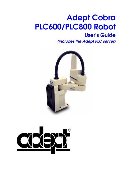
The <s<strong>tr</strong>ong>Adept</s<strong>tr</strong>ong> <s<strong>tr</strong>ong>Cobra</s<strong>tr</strong>ong> <s<strong>tr</strong>ong>PLC600</s<strong>tr</strong>ong> and PLC800 robots are four-axis SCARA robots (Selective<br />
Compliance Assembly Robot Arm). See Figure 1-2. Joints 1, 2, and 4 are rotational; Joint 3<br />
is <strong>tr</strong>anslational. See Figure 1-3 for a description of the robot joint locations.<br />
NOTE: The descriptions and ins<strong>tr</strong>uctions in this manual apply to both the<br />
<s<strong>tr</strong>ong>Cobra</s<strong>tr</strong>ong> <s<strong>tr</strong>ong>PLC600</s<strong>tr</strong>ong> and the <s<strong>tr</strong>ong>Cobra</s<strong>tr</strong>ong> PLC800, except for instances where there is<br />
a difference, as in dimension and work envelope drawings. In those cases<br />
the information is presented for both robots.<br />
Figure 1-2. <s<strong>tr</strong>ong>Adept</s<strong>tr</strong>ong> <s<strong>tr</strong>ong>Cobra</s<strong>tr</strong>ong> PLC800 Robot<br />
16 <s<strong>tr</strong>ong>Adept</s<strong>tr</strong>ong> <s<strong>tr</strong>ong>Cobra</s<strong>tr</strong>ong> <s<strong>tr</strong>ong>PLC600</s<strong>tr</strong>ong>/PLC800 Robot User’s <s<strong>tr</strong>ong>Guide</s<strong>tr</strong>ong>, Rev B
Product Description<br />
Joint 2<br />
Joint 1<br />
Joint 3<br />
Inner<br />
Link<br />
Outer<br />
Link<br />
Joint 4<br />
Figure 1-3. Robot Joint Motions<br />
Software<br />
The PLC Server software – used to provide seamless <s<strong>tr</strong>ong>com</s<strong>tr</strong>ong>munication between the PLC<br />
and the robot – is supplied with the system. The <s<strong>tr</strong>ong>Adept</s<strong>tr</strong>ong> PLC Server requires operating<br />
system version 16.1D6 or later. Additionally, it requires that the PLC Server Application<br />
license be installed on the <s<strong>tr</strong>ong>Adept</s<strong>tr</strong>ong> PLC Server.<br />
NOTE: The operating system and software license are installed at the<br />
<s<strong>tr</strong>ong>Adept</s<strong>tr</strong>ong> factory, before the system is shipped.<br />
The application software and robot location data reside on the customer-supplied PLC.<br />
See Chapter 6 for details.<br />
<s<strong>tr</strong>ong>Adept</s<strong>tr</strong>ong> <s<strong>tr</strong>ong>Cobra</s<strong>tr</strong>ong> <s<strong>tr</strong>ong>PLC600</s<strong>tr</strong>ong>/PLC800 Robot User’s <s<strong>tr</strong>ong>Guide</s<strong>tr</strong>ong>, Rev B 17
In<strong>tr</strong>oduction<br />
1.2 Installation Overview<br />
The system installation process is summarized in the following table. Refer also to the<br />
system cable diagram in Figure 4-1 on page 43.<br />
Table 1-1. Installation Overview<br />
Task to be Performed<br />
Reference Location<br />
1. Mount the robot on a flat, secure mounting surface. See Section 3.5 on page 36.<br />
2. Install the PLC Server, the Front Panel and any<br />
user-supplied equipment such as the PLC, PLC<br />
User Interface and PLC programming software.<br />
3. Install the IEEE 1394 and XSYS cables between<br />
the robot and PLC Server.<br />
4. Install the null-modem serial cable between the<br />
user-supplied PLC and the PLC Server.<br />
5. Create a 24 VDC cable and connect it between the<br />
robot and the user-supplied 24 VDC power supply.<br />
6. Create a 200-240 VAC cable and connect it<br />
between the robot and the facility AC power source.<br />
7. Create a 24 VDC cable and connect it between the<br />
PLC Server and the user-supplied 24 VDC power<br />
supply.<br />
8. Connect the workcell equipment to an earth<br />
grounding point.<br />
See Section 3.6 on page 38.<br />
See Section 4.4 on page 48.<br />
See Section 4.5 on page 48.<br />
See Section 4.6 on page 49.<br />
See Section 4.7 on page 52.<br />
See Section 4.8 on page 55.<br />
See Section 4.9 on page 57.<br />
9. Install user-supplied safety barriers in the workcell. See Section 4.10 on page 59.<br />
10.Read Chapter 5 to learn about <s<strong>tr</strong>ong>com</s<strong>tr</strong>ong>missioning the<br />
system, including system start-up and testing<br />
operation.<br />
11.Read Chapter 7 if you need to install optional robot<br />
equipment, including end-effectors, user air and<br />
elec<strong>tr</strong>ical lines, solenoids, etc.<br />
See Section 5.4 on page 73.<br />
See Section 7.1 on page 101.<br />
18 <s<strong>tr</strong>ong>Adept</s<strong>tr</strong>ong> <s<strong>tr</strong>ong>Cobra</s<strong>tr</strong>ong> <s<strong>tr</strong>ong>PLC600</s<strong>tr</strong>ong>/PLC800 Robot User’s <s<strong>tr</strong>ong>Guide</s<strong>tr</strong>ong>, Rev B
Product Description<br />
1.3 How Can I Get Help?<br />
Refer to the How to Get Help Resource <s<strong>tr</strong>ong>Guide</s<strong>tr</strong>ong> (<s<strong>tr</strong>ong>Adept</s<strong>tr</strong>ong> P/N 00961-00700) for details on<br />
getting assistance with your <s<strong>tr</strong>ong>Adept</s<strong>tr</strong>ong> software and hardware. Additionally, you can access<br />
information sources on <s<strong>tr</strong>ong>Adept</s<strong>tr</strong>ong>’s corporate web site:<br />
http://www.adept.<s<strong>tr</strong>ong>com</s<strong>tr</strong>ong><br />
<s<strong>tr</strong>ong>Adept</s<strong>tr</strong>ong> Document Library<br />
In addition to the <s<strong>tr</strong>ong>Adept</s<strong>tr</strong>ong> Document Library on CD-ROM, you can find <s<strong>tr</strong>ong>Adept</s<strong>tr</strong>ong> product<br />
documentation on the <s<strong>tr</strong>ong>Adept</s<strong>tr</strong>ong> website in the Document Library area. The Document<br />
Library search engine allows you to locate information on a specific topic. Additionally,<br />
the Document Menu provides a list of available product documentation.<br />
To access the <s<strong>tr</strong>ong>Adept</s<strong>tr</strong>ong> Document Library, type the following URL into your browser:<br />
http://www.adept.<s<strong>tr</strong>ong>com</s<strong>tr</strong>ong>/Main/KE/DATA/adept_search.htm<br />
or, select the Document Library link on the Home page of the <s<strong>tr</strong>ong>Adept</s<strong>tr</strong>ong> website.<br />
<s<strong>tr</strong>ong>Adept</s<strong>tr</strong>ong> <s<strong>tr</strong>ong>Cobra</s<strong>tr</strong>ong> <s<strong>tr</strong>ong>PLC600</s<strong>tr</strong>ong>/PLC800 Robot User’s <s<strong>tr</strong>ong>Guide</s<strong>tr</strong>ong>, Rev B 19
Safety 2<br />
2.1 Warnings, Cautions, and Notes in Manual<br />
There are four levels of special alert notation used in this manual. In descending order of<br />
importance, they are:<br />
DANGER: This indicates an imminently hazardous<br />
situation which, if not avoided, will result in death or<br />
serious injury.<br />
WARNING: This indicates a potentially hazardous<br />
situation which, if not avoided, could result in serious<br />
injury or major damage to the equipment.<br />
CAUTION: This indicates a situation which, if not avoided,<br />
could result in minor injury or damage to the equipment.<br />
NOTE: This provides supplementary information, emphasizes a point or<br />
procedure, or gives a tip for easier operation.<br />
<s<strong>tr</strong>ong>Adept</s<strong>tr</strong>ong> <s<strong>tr</strong>ong>Cobra</s<strong>tr</strong>ong> <s<strong>tr</strong>ong>PLC600</s<strong>tr</strong>ong>/PLC800 Robot User’s <s<strong>tr</strong>ong>Guide</s<strong>tr</strong>ong>, Rev B 21
Safety<br />
2.2 Warning Labels on the Robot<br />
Figure 2-1 and Figure 2-2 show the warning labels on the <s<strong>tr</strong>ong>Adept</s<strong>tr</strong>ong> <s<strong>tr</strong>ong>Cobra</s<strong>tr</strong>ong> PLC robots.<br />
Figure 2-1. Elec<strong>tr</strong>ical and Thermal Warning Labels on AIB Chassis<br />
Figure 2-2. Thermal Warning Label on Underside of Inner Link<br />
22 <s<strong>tr</strong>ong>Adept</s<strong>tr</strong>ong> <s<strong>tr</strong>ong>Cobra</s<strong>tr</strong>ong> <s<strong>tr</strong>ong>PLC600</s<strong>tr</strong>ong>/PLC800 Robot User’s <s<strong>tr</strong>ong>Guide</s<strong>tr</strong>ong>, Rev B
Warnings, Cautions, and Notes in Manual<br />
Figure 2-3. Warning Label on Encoder Cables<br />
WARNING: When the Outer link cover is removed, you<br />
see the label shown above. Do not remove the J3-ENC or<br />
J4-ENC encoder cable connectors from their sockets. If<br />
they are removed, the calibration data will be lost and the<br />
robot must be run through a factory calibration process,<br />
which requires special software and tools.<br />
<s<strong>tr</strong>ong>Adept</s<strong>tr</strong>ong> <s<strong>tr</strong>ong>Cobra</s<strong>tr</strong>ong> <s<strong>tr</strong>ong>PLC600</s<strong>tr</strong>ong>/PLC800 Robot User’s <s<strong>tr</strong>ong>Guide</s<strong>tr</strong>ong>, Rev B 23
Safety<br />
2.3 Precautions and Required Safeguards<br />
This manual must be read by all personnel who install, operate, or maintain <s<strong>tr</strong>ong>Adept</s<strong>tr</strong>ong><br />
systems, or who work within or near the workcell.<br />
WARNING: <s<strong>tr</strong>ong>Adept</s<strong>tr</strong>ong> Technology s<strong>tr</strong>ictly prohibits<br />
installation, <s<strong>tr</strong>ong>com</s<strong>tr</strong>ong>missioning, or operation of an <s<strong>tr</strong>ong>Adept</s<strong>tr</strong>ong><br />
robot without adequate safeguards according to<br />
applicable local and national standards. Installations in EU<br />
and EEA coun<strong>tr</strong>ies must <s<strong>tr</strong>ong>com</s<strong>tr</strong>ong>ply with EN 775/ISO 10218,<br />
especially sections 5,6; EN 292-2; and EN 60204-1,<br />
especially section 13.<br />
Safety Barriers<br />
Safety barriers must be an integral part of a robot workcell design. <s<strong>tr</strong>ong>Adept</s<strong>tr</strong>ong> systems are<br />
<s<strong>tr</strong>ong>com</s<strong>tr</strong>ong>puter-con<strong>tr</strong>olled and may activate remote devices under program con<strong>tr</strong>ol at times or<br />
along paths not anticipated by personnel. It is critical that safeguards be in place to<br />
prevent personnel from entering the workcell whenever equipment power is present.<br />
The robot system integrator, or end user, must ensure that adequate safeguards, safety<br />
barriers, light curtains, safety gates, safety floor mats, etc., will be installed. The robot<br />
workcell must be designed according to the applicable local and national standards (see<br />
Section 2.7 on page 28).<br />
The safe distance to the robot depends on the height of the safety fence. The height and<br />
the distance of the safety fence from the robot must ensure that personnel cannot reach the<br />
danger zone of the robot.<br />
The <s<strong>tr</strong>ong>Adept</s<strong>tr</strong>ong> con<strong>tr</strong>ol system has features that aid the user in cons<strong>tr</strong>ucting system safeguards,<br />
including customer emergency stop circui<strong>tr</strong>y and digital input and output lines. The<br />
emergency power-off circui<strong>tr</strong>y is capable of switching external power systems, and can be<br />
interfaced to the appropriate user-supplied safeguards. See Chapter 5 for information on<br />
safe and effective use of the robot.<br />
Impact and Trapping Points<br />
<s<strong>tr</strong>ong>Adept</s<strong>tr</strong>ong> robots are capable of moving at high speeds. If a person is s<strong>tr</strong>uck by a robot<br />
(impacted) or <strong>tr</strong>apped (pinched), death or serious injury could occur. Robot configuration,<br />
joint speed, joint orientation, and attached payload all con<strong>tr</strong>ibute to the total amount of<br />
energy available to cause injury.<br />
24 <s<strong>tr</strong>ong>Adept</s<strong>tr</strong>ong> <s<strong>tr</strong>ong>Cobra</s<strong>tr</strong>ong> <s<strong>tr</strong>ong>PLC600</s<strong>tr</strong>ong>/PLC800 Robot User’s <s<strong>tr</strong>ong>Guide</s<strong>tr</strong>ong>, Rev B
Warnings, Cautions, and Notes in Manual<br />
Additional Safety Information<br />
The standards and regulations listed in this handbook contain additional guidelines for<br />
robot system installation, safeguarding, maintenance, testing, startup, and operator<br />
<strong>tr</strong>aining. Table 2-1 on page 25 lists some sources for the various standards.<br />
Table 2-1. Sources for International Standards and Directives<br />
SEMI International Standards<br />
3081 Zanker Road<br />
San Jose, CA 95134<br />
USA<br />
American National Standards Institute (ANSI)<br />
11 West 42nd S<strong>tr</strong>eet, 13th Floor<br />
New York, NY 10036<br />
USA<br />
Phone: 1.408.943.6900<br />
Fax: 1.408.428.9600<br />
http://www.semi.org/web/wstandards.nsf<br />
BSI Group (British Standards)<br />
389 Chiswick High Road<br />
London W4 4AL<br />
United Kingdom<br />
Phone 212-642-4900<br />
Fax 212-398-0023<br />
http://www.ansi.org<br />
Document Center, Inc.<br />
1504 Indus<strong>tr</strong>ial Way, Unit 9<br />
Belmont, CA 94002<br />
USA<br />
Phone +44 (0)20 8996 9000<br />
Fax +44 (0)20 8996 7400<br />
http://www.bsi-global.<s<strong>tr</strong>ong>com</s<strong>tr</strong>ong><br />
DIN, Deutsches Institut für Normung e.V.<br />
German Institute for Standardization<br />
Burggrafens<strong>tr</strong>asse 6<br />
10787 Berlin<br />
Germany<br />
Phone.: +49 30 2601-0<br />
Fax: +49 30 2601-1231<br />
Phone 415-591-7600<br />
Fax 415-591-7617<br />
http://www.document-center.<s<strong>tr</strong>ong>com</s<strong>tr</strong>ong><br />
Global Engineering Documents<br />
15 Inverness Way East<br />
Englewood, CO 80112<br />
USA<br />
Phone 800-854-7179<br />
Fax 303-397-2740<br />
http://global.ihs.<s<strong>tr</strong>ong>com</s<strong>tr</strong>ong><br />
http://www.din.de<br />
http://www2.beuth.de/ (publishing)<br />
IEC, International Elec<strong>tr</strong>otechnical Commission<br />
Rue de Varembe 3<br />
PO Box 131<br />
CH-1211 Geneva 20<br />
Switzerland<br />
Phone 41 22 919-0211<br />
Fax 41 22 919-0300<br />
http://www.iec.ch<br />
Robotic Indus<strong>tr</strong>ies Association (RIA)<br />
900 Victors Way<br />
PO Box 3724<br />
Ann Arbor, MI 48106<br />
USA<br />
Phone 313-994-6088<br />
Fax 313-994-3338<br />
http://www.robotics.org<br />
<s<strong>tr</strong>ong>Adept</s<strong>tr</strong>ong> <s<strong>tr</strong>ong>Cobra</s<strong>tr</strong>ong> <s<strong>tr</strong>ong>PLC600</s<strong>tr</strong>ong>/PLC800 Robot User’s <s<strong>tr</strong>ong>Guide</s<strong>tr</strong>ong>, Rev B 25
Safety<br />
2.4 Intended Use of the Robots<br />
The installation and use of <s<strong>tr</strong>ong>Adept</s<strong>tr</strong>ong> products must <s<strong>tr</strong>ong>com</s<strong>tr</strong>ong>ply with all safety ins<strong>tr</strong>uctions and<br />
warnings in this manual. Installation and use must also <s<strong>tr</strong>ong>com</s<strong>tr</strong>ong>ply with all applicable local<br />
and national requirements and safety standards (see Section 2.7 on page 28).<br />
The <s<strong>tr</strong>ong>Adept</s<strong>tr</strong>ong> <s<strong>tr</strong>ong>Cobra</s<strong>tr</strong>ong> PLC 600 and PLC800 robots are intended for use in parts assembly and<br />
material handling for payloads less than 5.5 kg (12.1 lb).<br />
WARNING: For safety reasons, making certain<br />
modifications to <s<strong>tr</strong>ong>Adept</s<strong>tr</strong>ong> robots is prohibited (see<br />
Section 2.5).<br />
The <s<strong>tr</strong>ong>Adept</s<strong>tr</strong>ong> <s<strong>tr</strong>ong>Cobra</s<strong>tr</strong>ong> PLC robots and the <s<strong>tr</strong>ong>Adept</s<strong>tr</strong>ong> PLC Server are <s<strong>tr</strong>ong>com</s<strong>tr</strong>ong>ponent subassemblies of<br />
a <s<strong>tr</strong>ong>com</s<strong>tr</strong>ong>plete indus<strong>tr</strong>ial automation system. The PLC Server must be installed inside a<br />
suitable enclosure. The PLC Server must not <s<strong>tr</strong>ong>com</s<strong>tr</strong>ong>e into contact with liquids. Additionally,<br />
a standard <s<strong>tr</strong>ong>Adept</s<strong>tr</strong>ong> <s<strong>tr</strong>ong>Cobra</s<strong>tr</strong>ong> PLC robot must not <s<strong>tr</strong>ong>com</s<strong>tr</strong>ong>e into contact with liquids.<br />
The <s<strong>tr</strong>ong>Adept</s<strong>tr</strong>ong> equipment is not intended for use in any of the following situations:<br />
• In hazardous (explosive) atmospheres<br />
• In mobile, portable, marine, or aircraft systems<br />
• In life-support systems<br />
• In residential installations<br />
• In situations where the <s<strong>tr</strong>ong>Adept</s<strong>tr</strong>ong> equipment will be subject to ex<strong>tr</strong>emes of heat or<br />
humidity. See Table 3-1 on page 35 for allowable temperature and humidity<br />
ranges.<br />
WARNING: The ins<strong>tr</strong>uctions for installation, operation,<br />
and maintenance given in this User’s <s<strong>tr</strong>ong>Guide</s<strong>tr</strong>ong> must be<br />
s<strong>tr</strong>ictly observed.<br />
Non-intended use of an <s<strong>tr</strong>ong>Adept</s<strong>tr</strong>ong> <s<strong>tr</strong>ong>Cobra</s<strong>tr</strong>ong> PLC robot can:<br />
• Cause injury to personnel<br />
• Damage the robot or other equipment<br />
• Reduce system reliability and performance<br />
All persons that install, <s<strong>tr</strong>ong>com</s<strong>tr</strong>ong>mission, operate, or maintain the robot must:<br />
• Have the necessary qualifications<br />
• Read and follow exactly the ins<strong>tr</strong>uctions in this User’s <s<strong>tr</strong>ong>Guide</s<strong>tr</strong>ong><br />
26 <s<strong>tr</strong>ong>Adept</s<strong>tr</strong>ong> <s<strong>tr</strong>ong>Cobra</s<strong>tr</strong>ong> <s<strong>tr</strong>ong>PLC600</s<strong>tr</strong>ong>/PLC800 Robot User’s <s<strong>tr</strong>ong>Guide</s<strong>tr</strong>ong>, Rev B
Robot Modifications<br />
If there is any doubt concerning the application, ask <s<strong>tr</strong>ong>Adept</s<strong>tr</strong>ong> to determine if it is an<br />
intended use or not.<br />
2.5 Robot Modifications<br />
It is sometimes necessary to modify the robot in order to successfully integrate it into a<br />
workcell. Unfortunately, many seemingly simple modifications can either cause a robot<br />
failure or reduce the robot’s performance, reliability, or lifetime. The following<br />
information is provided as a guideline to modifications.<br />
Acceptable Modifications<br />
In general, the following robot modifications will not cause problems, but may affect<br />
robot performance:<br />
• Attaching tooling, utility boxes, solenoid packs, vacuum pumps, screwdrivers,<br />
lighting, etc., to the inner link, outer link, or J1 harness support.<br />
• Attaching hoses, pneumatic lines, or cables to the robot. These should be designed<br />
so they do not res<strong>tr</strong>ict joint motion or cause robot motion errors.<br />
Unacceptable Modifications<br />
The modifications listed below may damage the robot, reduce system safety and<br />
reliability, or shorten the life of the robot.<br />
CAUTION: Making any of the modifications outlined<br />
below will void the warranty of any <s<strong>tr</strong>ong>com</s<strong>tr</strong>ong>ponents that<br />
<s<strong>tr</strong>ong>Adept</s<strong>tr</strong>ong> determines were damaged due to the modification.<br />
You must contact <s<strong>tr</strong>ong>Adept</s<strong>tr</strong>ong> Customer Service if you are<br />
considering any of the following modifications.<br />
• Modifying any of the robot harnesses or robot-to-PLC Server cables.<br />
• Modifying any robot access covers or drive system <s<strong>tr</strong>ong>com</s<strong>tr</strong>ong>ponents.<br />
• Modifying, including drilling or cutting, any robot casting.<br />
• Modifying any robot elec<strong>tr</strong>ical <s<strong>tr</strong>ong>com</s<strong>tr</strong>ong>ponent or printed-circuit board.<br />
• Routing additional hoses, air lines, or wires through the robot.<br />
• Modifications that <s<strong>tr</strong>ong>com</s<strong>tr</strong>ong>promise EMC performance, including shielding.<br />
<s<strong>tr</strong>ong>Adept</s<strong>tr</strong>ong> <s<strong>tr</strong>ong>Cobra</s<strong>tr</strong>ong> <s<strong>tr</strong>ong>PLC600</s<strong>tr</strong>ong>/PLC800 Robot User’s <s<strong>tr</strong>ong>Guide</s<strong>tr</strong>ong>, Rev B 27
Safety<br />
2.6 Transport<br />
Always use adequate equipment to <strong>tr</strong>ansport and lift <s<strong>tr</strong>ong>Adept</s<strong>tr</strong>ong> products. See Chapter 3 for<br />
more information on <strong>tr</strong>ansporting, lifting, and installing.<br />
WARNING: Stay clear of the robot while it is being<br />
lifted/<strong>tr</strong>ansported.<br />
2.7 Safety Requirements for Additional Equipment<br />
Additional equipment used with the <s<strong>tr</strong>ong>Adept</s<strong>tr</strong>ong> <s<strong>tr</strong>ong>Cobra</s<strong>tr</strong>ong> PLC robot (grippers, conveyor belts,<br />
etc.) must not reduce the workcell safeguards.<br />
All emergency stop switches must always be accessible.<br />
If the robot is to be used in an EU or EEA member coun<strong>tr</strong>y, all <s<strong>tr</strong>ong>com</s<strong>tr</strong>ong>ponents in the robot<br />
workcell must <s<strong>tr</strong>ong>com</s<strong>tr</strong>ong>ply with the safety requirements in the European Machine Directive<br />
89/392/EEC (and subsequent amendments) and related harmonized European,<br />
international, and national standards. For robot systems, these include: EN 775/ISO<br />
10218, sections 5,6; EN 292-2; and EN 60204. For safety fences, see EN 294.<br />
In other coun<strong>tr</strong>ies, <s<strong>tr</strong>ong>Adept</s<strong>tr</strong>ong> s<strong>tr</strong>ongly re<s<strong>tr</strong>ong>com</s<strong>tr</strong>ong>mends, in addition to <s<strong>tr</strong>ong>com</s<strong>tr</strong>ong>plying with the<br />
applicable local and national regulations, that a similar level of safety be obtained.<br />
In the USA, applicable standards include ANSI/RIA R15.06 and ANSI/UL 1740.<br />
In Canada, applicable standards include CAN/CSA Z434.<br />
2.8 Sound Emissions<br />
The sound emission level of the <s<strong>tr</strong>ong>Adept</s<strong>tr</strong>ong> <s<strong>tr</strong>ong>Cobra</s<strong>tr</strong>ong> PLC robot depends on the speed and<br />
payload. The maximum value is 90dB(A), when running the robot at maximum<br />
AUTO-mode speed.<br />
WARNING: Acoustic emission from this robot may be up<br />
to 90dB(A) under worst-case conditions. Typical values<br />
will be lower, depending on payload, speed, acceleration,<br />
and mounting. Appropriate safety measures should be<br />
taken, such as ear protection and display of a warning<br />
sign.<br />
28 <s<strong>tr</strong>ong>Adept</s<strong>tr</strong>ong> <s<strong>tr</strong>ong>Cobra</s<strong>tr</strong>ong> <s<strong>tr</strong>ong>PLC600</s<strong>tr</strong>ong>/PLC800 Robot User’s <s<strong>tr</strong>ong>Guide</s<strong>tr</strong>ong>, Rev B
Thermal Hazard<br />
2.9 Thermal Hazard<br />
WARNING: You can burn yourself. Do not touch the robot<br />
base or outer link shortly after the robot has been running<br />
at high ambient temperatures (40-50°C) (104-122°F) or at<br />
fast cycle times (over 60 cycles per minute). The robot<br />
skin/surface temperature can exceed 85°C (185°F).<br />
2.10 Working Areas<br />
<s<strong>tr</strong>ong>Adept</s<strong>tr</strong>ong> robots have a Manual and an Automatic (AUTO) operating mode. While in<br />
Automatic mode, personnel are not allowed in the workcell.<br />
In Manual Mode, operators with additional safety equipment (see Section 2.12 on page<br />
30) are allowed to work in the robot workcell. For safety reasons the operator should,<br />
whenever possible, stay outside of the robot work envelope to prevent injury. The<br />
maximum speed and power of the robot is reduced but it could still cause injury to the<br />
operator.<br />
Before performing maintenance in the working envelope of the robot, High Power (robot<br />
power) must be switched off and the power supply of the robot must be disconnected.<br />
After these precautions, a skilled person is allowed to maintain the robot. See Section 2.11<br />
for the specifications.<br />
WARNING: Never remove any safeguarding and never<br />
make changes in the system that will de<s<strong>tr</strong>ong>com</s<strong>tr</strong>ong>mission a<br />
safeguard.<br />
2.11 Qualification of Personnel<br />
This manual assumes that all personnel have attended an <s<strong>tr</strong>ong>Adept</s<strong>tr</strong>ong> <strong>tr</strong>aining course and have<br />
a working knowledge of the system. The user must provide the necessary additional<br />
<strong>tr</strong>aining for all personnel who will be working with the system.<br />
As noted in this user’s guide, certain procedures should be performed only by skilled or<br />
ins<strong>tr</strong>ucted persons. For a description of the level of qualification, <s<strong>tr</strong>ong>Adept</s<strong>tr</strong>ong> uses the standard<br />
terms:<br />
• Skilled persons have technical knowledge or sufficient experience to enable them<br />
to avoid the dangers, elec<strong>tr</strong>ical and/or mechanical.<br />
• Ins<strong>tr</strong>ucted persons are adequately advised or supervised by skilled persons to<br />
enable them to avoid the dangers, elec<strong>tr</strong>ical and/or mechanical.<br />
<s<strong>tr</strong>ong>Adept</s<strong>tr</strong>ong> <s<strong>tr</strong>ong>Cobra</s<strong>tr</strong>ong> <s<strong>tr</strong>ong>PLC600</s<strong>tr</strong>ong>/PLC800 Robot User’s <s<strong>tr</strong>ong>Guide</s<strong>tr</strong>ong>, Rev B 29
Safety<br />
All personnel must observe sound safety practices during the installation, operation, and<br />
testing of all elec<strong>tr</strong>ically powered equipment. To avoid injury or damage to equipment,<br />
always remove power by disconnecting the AC power from the source before attempting<br />
any repair or upgrade activity. Use appropriate lockout procedures to reduce the risk of<br />
power being restored by another person while you are working on the system.<br />
WARNING: The user must get confirmation from every<br />
en<strong>tr</strong>usted person before they start working with the robot<br />
that the person:<br />
1. Has received the user’s guide.<br />
2. Has read the user’s guide.<br />
3. Understands the user’s guide and<br />
4. Will work in the manner specified by the user’s guide.<br />
2.12 Safety Equipment for Operators<br />
<s<strong>tr</strong>ong>Adept</s<strong>tr</strong>ong> advises operators to wear ex<strong>tr</strong>a safety equipment in the workcell. For safety<br />
reasons operators must wear the following when they are in the robot workcell.<br />
• Safety glasses<br />
• Protective headgear (hard hats)<br />
•Safety shoes<br />
Install warning signs around the workcell to ensure that anyone working around the<br />
robot system knows they must wear safety equipment.<br />
2.13 Protection Against Unauthorized Operation<br />
The system must be protected against unauthorized use. Res<strong>tr</strong>ict access to the keyboard<br />
and the Manual Con<strong>tr</strong>ol Pendant by locking them in a cabinet or use another adequate<br />
method to prevent access to them.<br />
2.14 Safety Aspects While Performing Maintenance<br />
Only skilled persons with the necessary knowledge about the safety and operating<br />
equipment are allowed to maintain the robot and PLC Server.<br />
WARNING: During maintenance and repair, the power to<br />
the robot and PLC Server must be turned off.<br />
Unauthorized third parties must be prevented from<br />
turning on power through the use of lockout measures.<br />
30 <s<strong>tr</strong>ong>Adept</s<strong>tr</strong>ong> <s<strong>tr</strong>ong>Cobra</s<strong>tr</strong>ong> <s<strong>tr</strong>ong>PLC600</s<strong>tr</strong>ong>/PLC800 Robot User’s <s<strong>tr</strong>ong>Guide</s<strong>tr</strong>ong>, Rev B
Risks Due to Incorrect Installation or Operation<br />
2.15 Risks Due to Incorrect Installation or Operation<br />
• Purposely defeating any aspect of the safety E-Stop system<br />
• Improper installation or programming of the robot system<br />
• Unauthorized use of cables other than those supplied or use of modified<br />
<s<strong>tr</strong>ong>com</s<strong>tr</strong>ong>ponents in the system<br />
• Defeating interlock so that operator can enter workcell with High Power ON<br />
Take precautions to ensure that these situations do not occur.<br />
2.16 What to Do in an Emergency Situation<br />
Press any E-Stop button (a red push-button on a yellow background/field) and then<br />
follow the internal procedures of your <s<strong>tr</strong>ong>com</s<strong>tr</strong>ong>pany or organization for an emergency<br />
situation. If a fire occurs, use CO 2 to extinguish the fire.<br />
<s<strong>tr</strong>ong>Adept</s<strong>tr</strong>ong> <s<strong>tr</strong>ong>Cobra</s<strong>tr</strong>ong> <s<strong>tr</strong>ong>PLC600</s<strong>tr</strong>ong>/PLC800 Robot User’s <s<strong>tr</strong>ong>Guide</s<strong>tr</strong>ong>, Rev B 31
Equipment Installation 3<br />
3.1 Unpacking and Inspecting the <s<strong>tr</strong>ong>Adept</s<strong>tr</strong>ong> Equipment<br />
Before Unpacking<br />
Carefully inspect all shipping crates for evidence of damage during <strong>tr</strong>ansit. Pay special<br />
attention to tilt and shock indication labels on the exteriors of the containers. If any<br />
damage is indicated, request that the carrier’s agent be present at the time the container is<br />
unpacked.<br />
Upon Unpacking<br />
Before signing the carrier’s delivery sheet, please <s<strong>tr</strong>ong>com</s<strong>tr</strong>ong>pare the actual items received (not<br />
just the packing slip) with your equipment purchase order and verify that all items are<br />
present and that the shipment is correct and free of visible damage.<br />
If the items received do not match the packing slip, or are damaged, do not sign the<br />
receipt. Contact <s<strong>tr</strong>ong>Adept</s<strong>tr</strong>ong> as soon as possible.<br />
If the items received do not match your order, please contact <s<strong>tr</strong>ong>Adept</s<strong>tr</strong>ong> immediately.<br />
Inspect each item for external damage as it is removed from its container. If any damage is<br />
evident, contact <s<strong>tr</strong>ong>Adept</s<strong>tr</strong>ong> (see Section 1.3 on page 19).<br />
Retain all containers and packaging materials. These items may be necessary to settle<br />
claims or, at a later date, to relocate equipment.<br />
3.2 Transport and Storage<br />
This equipment must be shipped and stored in a temperature-con<strong>tr</strong>olled environment,<br />
within the range –25°C to +55°C. The re<s<strong>tr</strong>ong>com</s<strong>tr</strong>ong>mended humidity range is 5 to 90 percent,<br />
non-condensing. It should be shipped and stored in the <s<strong>tr</strong>ong>Adept</s<strong>tr</strong>ong>-supplied packaging, which<br />
is designed to prevent damage from normal shock and vibration. You should protect the<br />
package from excessive shock and vibration.<br />
NOTE: The robot weighs 34 kg (75 lb) with no options installed.<br />
Use a forklift, pallet jack, or similar device to <strong>tr</strong>ansport and store the packaged equipment<br />
(see Figure 3-1).<br />
The robots must always be stored and shipped in an upright position in a clean, dry area<br />
that is free from condensation. Do not lay the crate on its side or any other position: this<br />
could damage the robot.<br />
<s<strong>tr</strong>ong>Adept</s<strong>tr</strong>ong> <s<strong>tr</strong>ong>Cobra</s<strong>tr</strong>ong> <s<strong>tr</strong>ong>PLC600</s<strong>tr</strong>ong>/PLC800 Robot User’s <s<strong>tr</strong>ong>Guide</s<strong>tr</strong>ong>, Rev B 33
Equipment Installation<br />
Eyebolt for lifting robot<br />
after robot has been<br />
unbolted from the<br />
<strong>tr</strong>ansportation pallet.<br />
Place forklift or pallet-jack here.<br />
Figure 3-1. <s<strong>tr</strong>ong>Cobra</s<strong>tr</strong>ong> <s<strong>tr</strong>ong>PLC600</s<strong>tr</strong>ong>/PLC800 Robot on a Transportation Pallet<br />
3.3 Repacking for Relocation<br />
If the robot or other equipment needs to be relocated, reverse the steps in the installation<br />
procedures that follow this chapter. Reuse all original packing containers and materials<br />
and follow all safety notes used for installation. Improper packaging for shipment will<br />
void your warranty. Before unbolting the robot from the mounting surface, fold the outer<br />
arm against the Joint 2 hardstops to help cen<strong>tr</strong>alize the center of gravity. The robot must<br />
always be shipped in an upright orientation. Specify this to the carrier if the robot is to be<br />
shipped.<br />
34 <s<strong>tr</strong>ong>Adept</s<strong>tr</strong>ong> <s<strong>tr</strong>ong>Cobra</s<strong>tr</strong>ong> <s<strong>tr</strong>ong>PLC600</s<strong>tr</strong>ong>/PLC800 Robot User’s <s<strong>tr</strong>ong>Guide</s<strong>tr</strong>ong>, Rev B
Repacking for Relocation<br />
3.4 Environmental and Facility Requirements<br />
The <s<strong>tr</strong>ong>Adept</s<strong>tr</strong>ong> robot system installation must meet the operating environment requirements<br />
shown in Table 3-1.<br />
Table 3-1. Robot System Operating Environment Requirements<br />
Ambient temperature<br />
Humidity<br />
Altitude<br />
5°C to 40°C (41°F to 104°F)<br />
5 to 90%, noncondensing<br />
up to 2000 m (6500 ft.)<br />
Pollution degree 2 (IEC 1131-2/EN 61131-2)<br />
Robot protection class IP20 (NEMA Type 1)<br />
Note: See Section 9.1 on page 127 for robot dimensions.<br />
<s<strong>tr</strong>ong>Adept</s<strong>tr</strong>ong> <s<strong>tr</strong>ong>Cobra</s<strong>tr</strong>ong> <s<strong>tr</strong>ong>PLC600</s<strong>tr</strong>ong>/PLC800 Robot User’s <s<strong>tr</strong>ong>Guide</s<strong>tr</strong>ong>, Rev B 35
Equipment Installation<br />
3.5 Mounting the Robot<br />
Mounting Surface<br />
The <s<strong>tr</strong>ong>Adept</s<strong>tr</strong>ong> <s<strong>tr</strong>ong>Cobra</s<strong>tr</strong>ong> PLC robot is designed to be mounted on a smooth, flat, level tabletop.<br />
The mounting s<strong>tr</strong>ucture must be rigid enough to prevent vibration and flexing during<br />
robot operation. <s<strong>tr</strong>ong>Adept</s<strong>tr</strong>ong> re<s<strong>tr</strong>ong>com</s<strong>tr</strong>ong>mends a 25 mm (1 in.) thick steel plate mounted to a rigid<br />
tube frame. Excessive vibration or mounting flexure will degrade robot performance.<br />
Figure 3-2 shows the mounting hole pattern for the <s<strong>tr</strong>ong>Adept</s<strong>tr</strong>ong> <s<strong>tr</strong>ong>Cobra</s<strong>tr</strong>ong> PLC robots.<br />
NOTE: On the under side of the base there is a hole and a slot that can be<br />
used as locating points for user-installed dowel pins in the mounting<br />
surface; see Figure 3-2. Using locating pins could improve the ability to<br />
remove and reinstall the robot in the same position.<br />
+0.015<br />
2x R4 0<br />
45<br />
6<br />
80<br />
160<br />
4X Ø 14 THRU<br />
10<br />
50<br />
160<br />
200<br />
+0.015<br />
Ø 8<br />
0<br />
6<br />
90<br />
234<br />
338<br />
Robot Mounting Procedure<br />
Figure 3-2. Mounting Hole Pattern for Robot<br />
1. Using the dimensions shown in Figure 3-2, drill and tap the mounting surface for<br />
four M12 - 1.75 x 36 mm (or 7/16 - 14 UNC x 1.50 in.) machine bolts (bolts not<br />
provided). See Table 3-2 for bolt and torque specifications.<br />
36 <s<strong>tr</strong>ong>Adept</s<strong>tr</strong>ong> <s<strong>tr</strong>ong>Cobra</s<strong>tr</strong>ong> <s<strong>tr</strong>ong>PLC600</s<strong>tr</strong>ong>/PLC800 Robot User’s <s<strong>tr</strong>ong>Guide</s<strong>tr</strong>ong>, Rev B
Repacking for Relocation<br />
2. While the robot is still bolted to the <strong>tr</strong>ansportation pallet, connect the hydraulic<br />
lift to the eyebolt at the top of the inner link (see Figure 3-1 on page 34). Take up<br />
any slack, but do not lift the robot at this time.<br />
WARNING: Do not attempt to lift the robot at any points<br />
other than the eyebolt provided. Do not attempt to extend<br />
the inner or outer links of the robot until the robot has<br />
been secured in position. Failure to <s<strong>tr</strong>ong>com</s<strong>tr</strong>ong>ply could result in<br />
the robot falling and causing either personnel injury or<br />
equipment damage.<br />
3. Remove the four bolts securing the robot base to the pallet. Retain these bolts for<br />
possible later relocation of the equipment.<br />
4. Lift the robot and position it directly over the mounting surface.<br />
5. Slowly lower the robot while aligning the base and the tapped mounting holes in<br />
the mounting surface.<br />
NOTE: The base casting of the robot is aluminum and can easily be<br />
dented if bumped against a harder surface. Verify that the robot is<br />
mounted squarely (will not rock back and forth) before tightening the<br />
mounting bolts.<br />
6. Install the customer-supplied mounting bolts and washers. Tighten bolts to<br />
torque specified in Table 3-2.<br />
WARNING: The center of mass of the robot may cause the<br />
robot to fall over if the robot is not secured with the<br />
mounting bolts.<br />
NOTE: Check the tightness of the mounting bolts one week after initial<br />
installation, and then recheck every 6 months. See Chapter 8 for periodic<br />
maintenance.<br />
Table 3-2. Mounting Bolt Torque Specifications<br />
Standard Size Specification Torque<br />
Me<strong>tr</strong>ic M12 x P1.75 ISO Property Class 8.8 85 N•m<br />
SAE 7/16-14 UNC SAE Grade 5 63 ft-lb<br />
<s<strong>tr</strong>ong>Adept</s<strong>tr</strong>ong> <s<strong>tr</strong>ong>Cobra</s<strong>tr</strong>ong> <s<strong>tr</strong>ong>PLC600</s<strong>tr</strong>ong>/PLC800 Robot User’s <s<strong>tr</strong>ong>Guide</s<strong>tr</strong>ong>, Rev B 37
Equipment Installation<br />
3.6 PLC Server Installation<br />
This equipment must be shipped and stored in a temperature-con<strong>tr</strong>olled environment. See<br />
Table 3-3. It should be shipped and stored in the <s<strong>tr</strong>ong>Adept</s<strong>tr</strong>ong>-supplied packaging, which is<br />
designed to prevent damage from normal shock and vibration. You should protect the<br />
package from shock and vibration.<br />
Table 3-3. Environmental Specifications<br />
Ambient temperature 5°C to 40°C<br />
Storage and shipment temperature<br />
Humidity range<br />
Altitude<br />
Free space around PLC Server (for proper<br />
cooling)<br />
–25°C to +55°C<br />
5 to 90%, nonconducting<br />
up to 2000 m (6500 feet)<br />
10 mm at back, 13 mm on sides<br />
Chassis protection class IP20 (NEMA Type 1)<br />
Re<s<strong>tr</strong>ong>com</s<strong>tr</strong>ong>mendations for customer-supplied<br />
enclosure for <s<strong>tr</strong>ong>Adept</s<strong>tr</strong>ong> PLC Server.<br />
(Mandatory for installations in EU or EEA<br />
coun<strong>tr</strong>ies.)<br />
Enclosure must meet EN 60204 (IEC 204)<br />
requirements and be rated at IP54.<br />
Unpacking the PLC Server<br />
Perform the steps below to unpack the PLC Server, optional Front Panel, and optional<br />
Manual Con<strong>tr</strong>ol Pendant (MCP). Then, see the later sections for information on mounting<br />
the equipment.<br />
1. Remove the PLC Server from its shipping container and place it near the robot. If<br />
rack mounting is required, refer to the section “Mounting the PLC Server” on<br />
page 39 for details.<br />
2. Remove the optional Front Panel from its shipping container and set it on a flat<br />
surface near the PLC Server.<br />
Repacking for Relocation<br />
If the PLC Server needs to be relocated, reverse the steps in the installation procedure.<br />
Reuse all original packing containers and materials and follow all safety notes used for<br />
installation. Improper packaging for shipment will void your warranty.<br />
Space Around the Chassis<br />
When the PLC Server is installed, you must allow 10 mm at the back of the unit and 13<br />
mm on the sides of the unit for proper air cooling. To facilitate installation, make sure that<br />
the factory installed CompactFlash Memory Card is in place within the PLC Server prior<br />
to mounting it. This is crucial if you plan to mount it in a way that res<strong>tr</strong>icts access to the<br />
side of the unit, and thus to the CompactFlash Memory <s<strong>tr</strong>ong>com</s<strong>tr</strong>ong>partment (see the<br />
“CompactFlash Memory Card” on page 41 for information).<br />
38 <s<strong>tr</strong>ong>Adept</s<strong>tr</strong>ong> <s<strong>tr</strong>ong>Cobra</s<strong>tr</strong>ong> <s<strong>tr</strong>ong>PLC600</s<strong>tr</strong>ong>/PLC800 Robot User’s <s<strong>tr</strong>ong>Guide</s<strong>tr</strong>ong>, Rev B
PLC Server Installation<br />
Mounting the PLC Server<br />
The following mounting options are available for the PLC Server:<br />
•Rack<br />
•Panel<br />
•Table<br />
In addition, the PLC Server can be stack mounted (one unit placed on top of another). See<br />
the sections below for information on mounting the PLC Server; page 93 for information<br />
on mounting the sDIO.<br />
NOTE: To maintain <s<strong>tr</strong>ong>com</s<strong>tr</strong>ong>pliance with EN 60204 in European installations,<br />
the mounting of the PLC Server and all terminations at the PLC Server<br />
must be performed in accordance with this standard.<br />
Rack Mounting the PLC Server<br />
To rack mount the PLC Server in a standard 19-inch equipment rack, install the optional<br />
mounting brackets on the side of the PLC Server, as shown in Figure 3-3. These brackets<br />
must be ordered separately, they do not <s<strong>tr</strong>ong>com</s<strong>tr</strong>ong>e with the PLC Server.<br />
190.0<br />
R 3.6<br />
2X 40356-00004<br />
3X M3 x 6MM<br />
BOTH SIDES<br />
88.1<br />
44.4<br />
2X 25.0<br />
21.8<br />
19.1<br />
3.6<br />
TYP.<br />
462.0<br />
482.8<br />
3.8<br />
14.2<br />
Figure 3-3. Rack Mounting the PLC Server<br />
<s<strong>tr</strong>ong>Adept</s<strong>tr</strong>ong> <s<strong>tr</strong>ong>Cobra</s<strong>tr</strong>ong> <s<strong>tr</strong>ong>PLC600</s<strong>tr</strong>ong>/PLC800 Robot User’s <s<strong>tr</strong>ong>Guide</s<strong>tr</strong>ong>, Rev B 39
Equipment Installation<br />
Panel Mounting the PLC Server<br />
To panel mount the PLC Server, install two brackets on each side at the rear of the unit, as<br />
shown in Figure 3-4. Use the screws from the accessories kit.<br />
200.5<br />
14.0<br />
27.4<br />
8.1<br />
8X M3 x 6MM<br />
273.9<br />
4X 40356-00000<br />
R3.6 TYP.<br />
16.0<br />
44.9<br />
16.1<br />
44.9<br />
6.6<br />
346.6<br />
359.8<br />
Figure 3-4. Panel Mounting the PLC Server<br />
40 <s<strong>tr</strong>ong>Adept</s<strong>tr</strong>ong> <s<strong>tr</strong>ong>Cobra</s<strong>tr</strong>ong> <s<strong>tr</strong>ong>PLC600</s<strong>tr</strong>ong>/PLC800 Robot User’s <s<strong>tr</strong>ong>Guide</s<strong>tr</strong>ong>, Rev B
PLC Server Installation<br />
Table Mounting the PLC Server<br />
To table mount the PLC Server, install two brackets on each side near the bottom of the<br />
unit, as shown in Figure 3-5. Use the screws from the accessories kit.<br />
4X 40356-00001<br />
R 3.6<br />
29.5<br />
12.1<br />
24.1<br />
120.9<br />
24.9<br />
378.6<br />
391.8<br />
4X M3 x 6MM<br />
BOTH SIDES<br />
16.2<br />
CompactFlash Memory Card<br />
Figure 3-5. Table Mounting the PLC Server<br />
16.0<br />
120.9<br />
21.6<br />
The PLC Server is equipped with a CompactFlash (CF) memory card. The PLC Server<br />
system uses a CF in place of a <strong>tr</strong>aditional hard disk drive. In fact, it is often referred to as a<br />
“solid state hard drive”. The CF is about half the size of a credit card and twice as thick. It<br />
has no moving parts and is therefore reliable and durable.<br />
The CF shipped with all systems has a capacity of 30 MB and is factory configured by<br />
<s<strong>tr</strong>ong>Adept</s<strong>tr</strong>ong>. The CF stores the PLC Server software.<br />
NOTE: <s<strong>tr</strong>ong>Adept</s<strong>tr</strong>ong> reserves the right to increase the size of the standard CF<br />
without notice.<br />
Not all types of CompactFlash are <s<strong>tr</strong>ong>com</s<strong>tr</strong>ong>patible with the PLC Server. <s<strong>tr</strong>ong>Adept</s<strong>tr</strong>ong> requires the use<br />
of the CF supplied by <s<strong>tr</strong>ong>Adept</s<strong>tr</strong>ong> at the time of the PLC Server purchase and that all<br />
replacement CF cards be obtained from <s<strong>tr</strong>ong>Adept</s<strong>tr</strong>ong>.<br />
CAUTION: Use suitable measures for eliminating<br />
elec<strong>tr</strong>ostatic discharge during handling of the<br />
CompactFlash. This includes, but is not limited to, the use<br />
of a grounded wrist s<strong>tr</strong>ap while performing this operation.<br />
<s<strong>tr</strong>ong>Adept</s<strong>tr</strong>ong> <s<strong>tr</strong>ong>Cobra</s<strong>tr</strong>ong> <s<strong>tr</strong>ong>PLC600</s<strong>tr</strong>ong>/PLC800 Robot User’s <s<strong>tr</strong>ong>Guide</s<strong>tr</strong>ong>, Rev B 41
Equipment Installation<br />
CAUTION: Never install or remove the CompactFlash<br />
when power is connected to the PLC Server.<br />
Installing CompactFlash<br />
To install a CompactFlash (CF) into a PLC Server:<br />
1. Make sure that the PLC Server is disconnected from its power source.<br />
2. Locate the CF <s<strong>tr</strong>ong>com</s<strong>tr</strong>ong>partment (see Figure 3-6).<br />
Eject Button<br />
CompactFlash<br />
Compartment<br />
Figure 3-6. CompactFlash Memory Card Compartment<br />
3. Carefully remove the CF from its shipping container. Locate the CF slot and<br />
position the card so its connector is facing towards the PLC Server and the label is<br />
facing up.<br />
4. Insert the CF into the PLC Server.<br />
Once installed, <s<strong>tr</strong>ong>Adept</s<strong>tr</strong>ong> re<s<strong>tr</strong>ong>com</s<strong>tr</strong>ong>mends that you do not repeatedly remove and insert the CF.<br />
42 <s<strong>tr</strong>ong>Adept</s<strong>tr</strong>ong> <s<strong>tr</strong>ong>Cobra</s<strong>tr</strong>ong> <s<strong>tr</strong>ong>PLC600</s<strong>tr</strong>ong>/PLC800 Robot User’s <s<strong>tr</strong>ong>Guide</s<strong>tr</strong>ong>, Rev B
R<br />
SmartServo<br />
IEEE-1394<br />
OK HPE LAN SW1 1.1 1.2 2.1 2.2<br />
SF ES HD 1 2 3 4<br />
ON<br />
OFF<br />
1 2 3<br />
XDIO<br />
R<br />
XUSR<br />
Device Net<br />
Eth 10/100<br />
XSYS<br />
CAMERA<br />
BELT ENCODER<br />
XFP<br />
RS-232/TERM<br />
RS-232-1<br />
XMCP<br />
RS-422/485<br />
RS-232-2<br />
*S/N 3562-XXXXX*<br />
XDC1 XDC2<br />
24V 5A<br />
-+ -+<br />
GND<br />
+24V<br />
DC INPUT<br />
(24 VDC)<br />
AC INPUT<br />
(200-240 VAC 1Φ)<br />
XIO<br />
XSLV<br />
1<br />
XPANEL<br />
2<br />
SmartServo<br />
RS-232<br />
Wiring the System 4<br />
4.1 System Cable Diagram<br />
Installation Procedure:<br />
1. Connect PLC Server SmartServo port 1.1 to robot SmartServo port 1.<br />
2. Connect PLC Server XSYS to robot XSLV.<br />
3. Verify terminator plug is installed in XUSR connector.<br />
4. Connect null-modem serial cable from PLC serial port to PLC Server RS-232-1.<br />
5. Connect Front Panel XFP to PLC Server XFP<br />
6. Connect 24 VDC to PLC Server XDC1 and to robot +24V DC Input<br />
7. Connect 200-240 VAC to AC Input on robot Interface Panel, secure with clamp.<br />
8. Connect ground wire to 24 VDC power supply, PLC Server, robot, and PLC.<br />
9. Connect optional PC and/or PLC Interface to PLC.<br />
<br />
<s<strong>tr</strong>ong>Adept</s<strong>tr</strong>ong><br />
PLC Server<br />
Terminator<br />
Installed<br />
User-Supplied Ground Wire<br />
<br />
<br />
PLC Server (XFP) to<br />
Front Panel (XFP)<br />
STOP<br />
Front Panel<br />
<br />
<br />
PLC Server SmartServo (Port 1.1) to<br />
Robot SmartServo (Port 1)<br />
SmartCon<strong>tr</strong>oller CX<br />
<br />
PLC Server (XSYS) to<br />
Robot (XSLV)<br />
24VDC Power<br />
to Robot<br />
(+24V DC Input)<br />
24VDC Power to<br />
PLC Server (XDC1)<br />
DF1 Protocol<br />
<br />
<br />
<s<strong>tr</strong>ong>Adept</s<strong>tr</strong>ong> <s<strong>tr</strong>ong>Cobra</s<strong>tr</strong>ong><br />
<s<strong>tr</strong>ong>PLC600</s<strong>tr</strong>ong>/800 Robot<br />
CUSTOMER-SUPPLIED<br />
COMPONENTS<br />
<br />
<br />
User-Supplied Ground Wire<br />
Optional desktop or notebook PC<br />
running PLC-programming software<br />
Programmable Logic<br />
Con<strong>tr</strong>oller (PLC)<br />
Optional PLC<br />
Interface<br />
<br />
User-Supplied<br />
24VDC Power<br />
Supply<br />
User-Supplied<br />
Ground Wire on<br />
Robot Base<br />
User-Supplied Ground Wire<br />
User-Supplied<br />
200-240 VAC,<br />
single phase<br />
Figure 4-1. System Cable Diagram for <s<strong>tr</strong>ong>Adept</s<strong>tr</strong>ong> <s<strong>tr</strong>ong>Cobra</s<strong>tr</strong>ong> PLC Robots<br />
<br />
<br />
<br />
<s<strong>tr</strong>ong>Adept</s<strong>tr</strong>ong> <s<strong>tr</strong>ong>Cobra</s<strong>tr</strong>ong> <s<strong>tr</strong>ong>PLC600</s<strong>tr</strong>ong>/PLC800 Robot User’s <s<strong>tr</strong>ong>Guide</s<strong>tr</strong>ong>, Rev B 43
Wiring the System<br />
4.2 <s<strong>tr</strong>ong>Cobra</s<strong>tr</strong>ong> PLC Robot Interface Panel Connectors<br />
200-240 VAC<br />
Input<br />
XSLV<br />
Ground<br />
Pin<br />
24 VDC<br />
Input<br />
SmartServo Port 1<br />
SmartServo Port 2<br />
+24 VDC<br />
Pin<br />
RS-232<br />
XIO<br />
XPANEL<br />
Figure 4-2. Robot Interface Panel<br />
24 VDC - for connecting user-supplied 24 VDC power to the robot. The mating connector<br />
is provided.<br />
200/240VAC - for connecting 200-240 VAC, single-phase, input power to the robot. The<br />
mating connector is provided.<br />
XSLV - for connecting the supplied XSYS cable from the PLC Server XSYS connector.<br />
(DB-9, female)<br />
SmartServo 1/2 - for connecting the IEEE 1394 cable from the PLC Server (SmartServo<br />
1.1) to the robot upper connector (SmartServo 1).<br />
NOTE: The robot lower connector (SmartServo 2) is not used.<br />
RS-232 - NOT USED.<br />
XPANEL - NOT USED.<br />
XIO - NOT USED.<br />
44 <s<strong>tr</strong>ong>Adept</s<strong>tr</strong>ong> <s<strong>tr</strong>ong>Cobra</s<strong>tr</strong>ong> <s<strong>tr</strong>ong>PLC600</s<strong>tr</strong>ong>/PLC800 Robot User’s <s<strong>tr</strong>ong>Guide</s<strong>tr</strong>ong>, Rev B
PLC Server Connectors and Indicators<br />
4.3 PLC Server Connectors and Indicators<br />
*S/N 3562-XXXXX*<br />
R<br />
CAMERA<br />
RS-232/TERM<br />
RS-422/485<br />
OK HPE LAN<br />
SF ES HD<br />
1 2 3<br />
SmartServo<br />
IEEE-1394<br />
SW1 1.1 1.2 2.1 2.2<br />
1 2 3 4<br />
ON<br />
OFF<br />
XDIO<br />
XUSR<br />
Device Net<br />
Eth 10/100<br />
XSYS<br />
BELT ENCODER<br />
XFP<br />
RS-232-1<br />
XMCP<br />
RS-232-2<br />
XDC1 XDC2<br />
SmartCon<strong>tr</strong>oller CX<br />
24V<br />
5A<br />
-+ -+<br />
Figure 4-3. <s<strong>tr</strong>ong>Adept</s<strong>tr</strong>ong> PLC Server<br />
NOTE: All the connectors on the PLC Server use standard density<br />
spacing, D-subminiature connectors. For customization purposes, the<br />
user needs to provide connectors of the appropriate gender and pin count<br />
or use optional <s<strong>tr</strong>ong>Adept</s<strong>tr</strong>ong> cables.<br />
1. Top Three Status LEDs<br />
The top three two-color LEDs indicate diagnostic test, power con<strong>tr</strong>ol, and <s<strong>tr</strong>ong>com</s<strong>tr</strong>ong>munication<br />
status.<br />
Table 4-1. PLC Server LEDs<br />
LED Green Indicates Red Indicates<br />
OK/SF System OK System Fault<br />
HPE/ES High Power Enabled E-Stop Open<br />
LAN/HD Ethernet Access Read/Write from<br />
CompactFlash<br />
During system bootup, the red OK/SF and HPE/ES LEDs are lit and the red LAN/HD<br />
LED blinks. After system bootup, the OK/SF LED should show green. If the HPE/ES LED<br />
shows red, the E-Stop circuit is open. During CompactFlash reads and writes, the<br />
LAN/HD LED pulses red. When the PLC Server is active on an Ethernet network, the<br />
LAN/HD LED pulses green.<br />
2. Bottom Three Status LEDs<br />
The bottom three LEDs on the front of the PLC Server indicate the status of the PLC Server<br />
while the system is starting up. The LEDs “count” with green patterns while the operating<br />
system is being loaded from disk.<br />
One of the patterns listed in Table 4-2 is displayed if an error occurs. If the PLC Server<br />
displays any of those errors, cycle the power off, then on again. If the problem persists,<br />
contact <s<strong>tr</strong>ong>Adept</s<strong>tr</strong>ong> Customer Service.<br />
If no error occurs during startup, all the LEDs are turned off briefly while the PLC Server<br />
application is loaded and started up. Then, one of the patterns listed in Table 11-1, “PLC<br />
Server Messages,” on page 149, is displayed to indicate the status of the PLC Server<br />
application.<br />
<s<strong>tr</strong>ong>Adept</s<strong>tr</strong>ong> <s<strong>tr</strong>ong>Cobra</s<strong>tr</strong>ong> <s<strong>tr</strong>ong>PLC600</s<strong>tr</strong>ong>/PLC800 Robot User’s <s<strong>tr</strong>ong>Guide</s<strong>tr</strong>ong>, Rev B 45
Wiring the System<br />
Table 4-2. LED Status Indicators<br />
LED Display<br />
1 2 3<br />
Description<br />
- - - No error.<br />
R - - System clock is dead or too fast. Clock interrupts<br />
are not being received.<br />
- R - Hardware configuration error.<br />
- - R Memory test failure. Free storage error.<br />
- R R Software serial I/O configuration error.<br />
R R R<br />
G - -<br />
Initial display set by hardware before software<br />
has started.<br />
Transient display set when PCI is configured.<br />
- - G Uninitialized <strong>tr</strong>ap.<br />
G - G<br />
Bus error detected.<br />
LED Display Key:<br />
- = Off G = Green R = Red<br />
If the PLC Server displays any of the above errors, cycle the power off, then on again. If<br />
the problem persists, then contact <s<strong>tr</strong>ong>Adept</s<strong>tr</strong>ong> Customer Service.<br />
3. SW1 DIP switches<br />
The DIP switches define certain configuration settings.<br />
NOTE: The DIP switches are set at the factory and must not be changed by<br />
the user.<br />
4. SmartServo 1.1 and 1.2<br />
These ports connect any approved products onto <s<strong>tr</strong>ong>Adept</s<strong>tr</strong>ong>’s 1394-based servo network. For<br />
this product, these ports are used to connect to the <s<strong>tr</strong>ong>Cobra</s<strong>tr</strong>ong> PLC robot only.<br />
WARNING: Remove power from the PLC Server before<br />
plugging in or unplugging any IEEE-1394 cables to or<br />
from these connectors. Failure to remove power could<br />
result in unpredictable behavior by the system.<br />
5. IEEE-1394 2.1 and 2.2 connectors<br />
Not used.<br />
6. DeviceNet connector<br />
Not used.<br />
46 <s<strong>tr</strong>ong>Adept</s<strong>tr</strong>ong> <s<strong>tr</strong>ong>Cobra</s<strong>tr</strong>ong> <s<strong>tr</strong>ong>PLC600</s<strong>tr</strong>ong>/PLC800 Robot User’s <s<strong>tr</strong>ong>Guide</s<strong>tr</strong>ong>, Rev B
PLC Server Connectors and Indicators<br />
7. Ethernet (Eth 10/100) connector<br />
Not used.<br />
8. Belt Encoder connector<br />
Not used.<br />
9. Camera connector<br />
Not used.<br />
10. RS-232-1 connector<br />
Connects the user-supplied PLC to the <s<strong>tr</strong>ong>Adept</s<strong>tr</strong>ong> PLC server. This connection provides the<br />
<s<strong>tr</strong>ong>com</s<strong>tr</strong>ong>munications link between the PLC Server/<s<strong>tr</strong>ong>Cobra</s<strong>tr</strong>ong> PLC robot and the user-supplied<br />
PLC using the DF1 Protocol.<br />
11. RS-232-2 connector<br />
Not used.<br />
12. RS-232/TERM connector<br />
Not used.<br />
13. RS-422/RS-485 connector<br />
Not used.<br />
14. XDIO connector<br />
This connector includes 20 signal pairs; 8 digital outputs (100 mA max) and 12 digital<br />
inputs, including four fast inputs (the first four input signals on this connector are the<br />
only input signals that can be configured as fast inputs). The digital outputs are<br />
short-circuit protected. This connector also supplies 24 VDC power for customer<br />
equipment. See Section 4.11 on page 66 for more information.<br />
15. XUSR connector<br />
Provides switch functions for emergency stop (E-Stop) and Manual/Automatic interfaces<br />
to external push buttons and other equipment. For example, an external E-Stop can be<br />
connected to the XUSR connector. A line E-Stop from other equipment can be connected.<br />
A muted safety gate that causes an E-Stop only in Automatic mode is included. Also<br />
included are contacts to report the status of E-Stop push buttons and the<br />
Manual/Automatic switch.<br />
NOTE: The PLC Server ships with a terminator plug attached to the XUSR<br />
connector. The terminator plug must be installed in the absence of any<br />
customer-supplied safety devices to close the E-Stop circuit. For more<br />
information about the XUSR connector, see Section 4.10 on page 59.<br />
16. XSYS connector<br />
Connects to AIB unit on the <s<strong>tr</strong>ong>Cobra</s<strong>tr</strong>ong> PLC. This connection is used for internal <s<strong>tr</strong>ong>Adept</s<strong>tr</strong>ong> signals<br />
for high power relays.<br />
17. XFP connector<br />
Connects to the Front Panel. See Section 4.10 on page 59 for information.<br />
18. XMCP connector<br />
Not used. The PLC Server ships with a terminator plug attached to the XMCP connector.<br />
<s<strong>tr</strong>ong>Adept</s<strong>tr</strong>ong> <s<strong>tr</strong>ong>Cobra</s<strong>tr</strong>ong> <s<strong>tr</strong>ong>PLC600</s<strong>tr</strong>ong>/PLC800 Robot User’s <s<strong>tr</strong>ong>Guide</s<strong>tr</strong>ong>, Rev B 47
Wiring the System<br />
19. XDC1 and XDC2 24 VDC connectors<br />
Connect power from a customer-supplied 24 VDC power supply to the XDC1 connector<br />
(see the “Connecting Power” on page 30 for information).<br />
4.4 Cable Connections from Robot to PLC Server<br />
This section describes the procedure for connecting the cables between the robot and PLC<br />
Server.<br />
1. Locate the IEEE 1394 cable (length 4.5M) and the XSYS cable (length 4.5M). They<br />
are typically shipped in the cable/accessories box.<br />
2. Install one end of the IEEE 1394 cable into the SmartServo port 1.1 connector on<br />
the PLC Server, and install the other end into the SmartServo port 1 connector on<br />
the robot interface panel. See Figure 4-1 on page 43.<br />
3. Install the XSYS cable between the robot interface panel XSLV safety interlock<br />
connector and XSYS connector on the PLC Server, and tighten the latching screws.<br />
4.5 Cable Connections from the PLC to PLC Server<br />
The user-supplied PLC is connected to the PLC Server through a null-modem serial cable.<br />
The cable connects to the PLC’s RS-232 port (typically, channel 0) and to the PLC Server’s<br />
RS-232-1 port (9-pin, male, D-sub).<br />
Table 4-3. PLC to PLC Server Cable Pin Description<br />
Signal <s<strong>tr</strong>ong>Adept</s<strong>tr</strong>ong> DB-9 Pin AB PLC DB-9 Pin<br />
TD (Transmit Data) 2 3<br />
RD (Receive Data) 3 2<br />
RTS (Request To Send) 8 7<br />
CTS (Clear To Send) 7 8<br />
SG (Signal Ground) 5 5<br />
DSR (Data Set Ready) 4 6<br />
CD (Carrier Detect) 4 1<br />
DTR (Data Terminal Ready) 1 4<br />
DTR (Data Terminal Ready) 6 4<br />
The PLC's RS-232 <s<strong>tr</strong>ong>com</s<strong>tr</strong>ong>munication port must be configured to use:<br />
• DF1 Full Duplex driver<br />
48 <s<strong>tr</strong>ong>Adept</s<strong>tr</strong>ong> <s<strong>tr</strong>ong>Cobra</s<strong>tr</strong>ong> <s<strong>tr</strong>ong>PLC600</s<strong>tr</strong>ong>/PLC800 Robot User’s <s<strong>tr</strong>ong>Guide</s<strong>tr</strong>ong>, Rev B
Connecting 24 VDC Power to Robot<br />
•No parity<br />
• No handshaking<br />
• CRC error checking<br />
• 38,400 bps (re<s<strong>tr</strong>ong>com</s<strong>tr</strong>ong>mended), 19,200 bps may also be used.<br />
Please refer to Chapter 6 for more information on configuring the PLC <s<strong>tr</strong>ong>com</s<strong>tr</strong>ong>munication<br />
interface.<br />
4.6 Connecting 24 VDC Power to Robot<br />
NOTE: This section provides information on the 24 VDC power supply<br />
and making the 24 VDC power cable. If you have ordered the optional<br />
Starter Kit, then you can skip to “Installing 24 VDC Robot Cable” on<br />
page 51.<br />
Specifications for 24 VDC Power<br />
Table 4-4. Specifications for 24 VDC User-Supplied Power Supply<br />
User-Supplied Power Supply<br />
Circuit Protection<br />
Power Cabling<br />
Shield Termination (re<s<strong>tr</strong>ong>com</s<strong>tr</strong>ong>mended for<br />
<s<strong>tr</strong>ong>com</s<strong>tr</strong>ong>pliance with EN Standards)<br />
24 VDC (+/- 10%), 150W (6A)<br />
(21.6 V< V in < 26.4 V)<br />
Not more than 15A (below the amperage<br />
rating of the cable used)<br />
1.5 – 1.85mm² (16-14 AWG)<br />
Braided shield connected to “-” terminal at<br />
both ends of cable. See Figure 4-4 on<br />
page 51.<br />
Details for 24 VDC Mating Connector<br />
The 24 VDC mating connector and two pins are supplied with each system. They are<br />
typically shipped in the cable/accessories box.<br />
Table 4-5. 24 VDC Mating Connector Specs<br />
Connector Details<br />
Ground<br />
24 VDC<br />
Connector receptacle, 2 position,<br />
type:<br />
Molex Saber, 18A, 2-Pin<br />
Molex P/N 44441-2002<br />
Digi-Key P/N WM18463-ND<br />
<s<strong>tr</strong>ong>Adept</s<strong>tr</strong>ong> <s<strong>tr</strong>ong>Cobra</s<strong>tr</strong>ong> <s<strong>tr</strong>ong>PLC600</s<strong>tr</strong>ong>/PLC800 Robot User’s <s<strong>tr</strong>ong>Guide</s<strong>tr</strong>ong>, Rev B 49
Wiring the System<br />
Table 4-5. 24 VDC Mating Connector Specs<br />
Pin Details<br />
Molex connector crimp terminal,<br />
female, 14-18 AWG<br />
Molex P/N 43375-0001<br />
Digi-Key P/N WM18493-ND<br />
Re<s<strong>tr</strong>ong>com</s<strong>tr</strong>ong>mended crimping tool, Molex Hand<br />
Crimper<br />
Molex P/N 63811-0400<br />
Digi-Key P/N WM9907-ND<br />
50 <s<strong>tr</strong>ong>Adept</s<strong>tr</strong>ong> <s<strong>tr</strong>ong>Cobra</s<strong>tr</strong>ong> <s<strong>tr</strong>ong>PLC600</s<strong>tr</strong>ong>/PLC800 Robot User’s <s<strong>tr</strong>ong>Guide</s<strong>tr</strong>ong>, Rev B
Connecting 24 VDC Power to Robot<br />
Procedure for Creating 24 VDC Cable<br />
1. Locate the connector and pins from Table 4-5 on page 49.<br />
2. Use 14-16 AWG wire to create the 24 VDC cable. Select the wire length to safely<br />
reach from the user-supplied 24 VDC power supply to the robot base.<br />
NOTE: You also must create a separate 24 VDC cable for the PLC Server.<br />
That cable uses a different style of connector. See Section 4.8 on page 55<br />
for details.<br />
3. Crimp the pins onto the wires using the crimping tool re<s<strong>tr</strong>ong>com</s<strong>tr</strong>ong>mended in Table 4-5<br />
on page 49.<br />
4. Insert the pins into the connector. Confirm that the 24V and ground wires are in<br />
the correct terminals in the plug.<br />
5. Prepare the opposite end of the cable for connection to your user-supplied 24<br />
VDC power supply.<br />
Installing 24 VDC Robot Cable<br />
1. Connect one end of the 24 VDC cable to your user-supplied 24 VDC power<br />
supply. Do not turn on the 24 VDC power until ins<strong>tr</strong>ucted to do so in Chapter 5.<br />
2. Plug the mating connector end of the 24 VDC cable into the 24 VDC connector on<br />
the interface panel on the back of the robot.<br />
<s<strong>tr</strong>ong>Adept</s<strong>tr</strong>ong> <s<strong>tr</strong>ong>Cobra</s<strong>tr</strong>ong><br />
i600/i800 Robot<br />
– +<br />
Shield<br />
User-Supplied Shielded<br />
Power Cable<br />
+<br />
–<br />
User-Supplied<br />
Power Supply<br />
24VDC<br />
Optional User<br />
Equipment<br />
Figure 4-4. User-Supplied 24 VDC Cable<br />
NOTE: In order to maintain <s<strong>tr</strong>ong>com</s<strong>tr</strong>ong>pliance with EN standards, DC power<br />
must be delivered over a shielded cable, with the shield connected to the<br />
return conductors at both ends of the cable.<br />
<s<strong>tr</strong>ong>Adept</s<strong>tr</strong>ong> <s<strong>tr</strong>ong>Cobra</s<strong>tr</strong>ong> <s<strong>tr</strong>ong>PLC600</s<strong>tr</strong>ong>/PLC800 Robot User’s <s<strong>tr</strong>ong>Guide</s<strong>tr</strong>ong>, Rev B 51
Wiring the System<br />
4.7 Connecting 200-240 VAC Power to Robot<br />
Specifications for AC Power<br />
Table 4-6. Specifications for 200/240VAC User-Supplied Power Supply<br />
Auto-Ranging<br />
Nominal<br />
Voltage<br />
Ranges<br />
Minimum<br />
Operating<br />
Voltage a<br />
Maximum<br />
Operating<br />
Voltage<br />
Frequency/<br />
Phasing<br />
Re<s<strong>tr</strong>ong>com</s<strong>tr</strong>ong>mended<br />
External Circuit<br />
Breaker,<br />
User-Supplied<br />
200V to 240V 180V 264V 50/60Hz<br />
1-phase<br />
10 Amps<br />
a Specifications are established at nominal line voltage. Low line voltage can affect robot<br />
performance.<br />
DANGER: AC power installation must be performed by a<br />
skilled and ins<strong>tr</strong>ucted person - see Section 2.11 on<br />
page 29. During installation, fail-safe lockout measures<br />
must be used to prevent unauthorized third parties from<br />
turning on power.<br />
Facility Overvoltage Protection<br />
The user must protect the robot from excessive overvoltages and voltage spikes. If the<br />
coun<strong>tr</strong>y of installation requires a CE-certified installation, or <s<strong>tr</strong>ong>com</s<strong>tr</strong>ong>pliance with IEC 1131-2,<br />
the following information may be helpful: IEC 1131-2 requires that the installation must<br />
ensure that Category II overvoltages (i.e., line spikes not directly due to lightning s<strong>tr</strong>ikes)<br />
are not exceeded. Transient overvoltages at the point of connection to the power source<br />
shall be con<strong>tr</strong>olled not to exceed overvoltage Category II, i.e., not higher than the impulse<br />
voltage corresponding to the rated voltage for the basic insulation. The user-supplied<br />
equipment or <strong>tr</strong>ansient suppressor shall be capable of absorbing the energy in the<br />
<strong>tr</strong>ansient.<br />
In the indus<strong>tr</strong>ial environment, nonperiodic overvoltage peaks may appear on mains<br />
power supply lines as a result of power interruptions to high-energy equipment (such as a<br />
blown fuse on one branch in a 3-phase system). This will cause high current pulses at<br />
relatively low voltage levels. The user shall take the necessary steps to prevent damage to<br />
the robot system (such as by interposing a <strong>tr</strong>ansformer). See IEC 1131-4 for additional<br />
information.<br />
52 <s<strong>tr</strong>ong>Adept</s<strong>tr</strong>ong> <s<strong>tr</strong>ong>Cobra</s<strong>tr</strong>ong> <s<strong>tr</strong>ong>PLC600</s<strong>tr</strong>ong>/PLC800 Robot User’s <s<strong>tr</strong>ong>Guide</s<strong>tr</strong>ong>, Rev B
Connecting 24 VDC Power to Robot<br />
AC Power Diagrams<br />
1Ø<br />
200–240VAC<br />
20A<br />
L<br />
N<br />
E<br />
Note: F1 is user-supplied, must be slow blow.<br />
F1 10A<br />
L = Line<br />
N = Neu<strong>tr</strong>al<br />
E = Earth Ground<br />
E<br />
N<br />
L<br />
<s<strong>tr</strong>ong>Adept</s<strong>tr</strong>ong> <s<strong>tr</strong>ong>Cobra</s<strong>tr</strong>ong>PLC<br />
600/800 Robots<br />
1Ø 200–240VAC<br />
User-Supplied<br />
AC Power Cable<br />
Figure 4-5. Typical AC Power Installation with Single-Phase Supply<br />
3Ø<br />
200–240VAC<br />
L1<br />
L2<br />
L3<br />
Note: F4 and F5 are user-supplied, must be slow blow.<br />
F5 10A<br />
200–240VAC<br />
F4 10A<br />
E<br />
User-Supplied<br />
AC Power Cable<br />
E<br />
N<br />
L<br />
L = Line 1<br />
N = Line 2<br />
E = Earth Ground<br />
<s<strong>tr</strong>ong>Adept</s<strong>tr</strong>ong> <s<strong>tr</strong>ong>Cobra</s<strong>tr</strong>ong>PLC<br />
600/800 Robots<br />
1Ø 200–240VAC<br />
Figure 4-6. Single-Phase AC Power Installation from a Three-Phase AC Supply<br />
<s<strong>tr</strong>ong>Adept</s<strong>tr</strong>ong> <s<strong>tr</strong>ong>Cobra</s<strong>tr</strong>ong> <s<strong>tr</strong>ong>PLC600</s<strong>tr</strong>ong>/PLC800 Robot User’s <s<strong>tr</strong>ong>Guide</s<strong>tr</strong>ong>, Rev B 53
Wiring the System<br />
Details for AC Mating Connector<br />
The AC mating connector is supplied with each system. It is typically shipped in the<br />
cable/accessories box. The supplied plug is internally labeled for the AC power<br />
connections (L, E, N).<br />
Table 4-7. AC Mating Connector Details<br />
AC Connector details<br />
AC in-line power plug,<br />
s<strong>tr</strong>aight, female, screw<br />
terminal, 10 A, 250 VAC<br />
Qualtek P/N 709-00/00<br />
Digi-Key P/N Q217-ND<br />
Procedure for Creating 200-240 VAC Cable<br />
1. Locate the AC mating connector shown in Table 4-7.<br />
2. Open the connector by unscrewing the screw on the shell and removing the cover.<br />
3. Loosen the two screws on the cable clamp. See Figure 4-7 on page 55.<br />
4. Use 18 AWG wire to create the AC power cable. Select the wire length to safely<br />
reach from the user-supplied AC power source to the robot base.<br />
5. S<strong>tr</strong>ip approximately 18 to 24 mm insulation from each of the three wires.<br />
6. Insert the wires into the connector through the removable bushing.<br />
7. Connect each wire to the correct terminal screw, and tighten the screw firmly.<br />
8. Tighten the screws on the cable clamp.<br />
9. Replace the cover and tighten the screw to seal the connector.<br />
10. Prepare the opposite end of the cable for connection to the facility AC power<br />
source.<br />
54 <s<strong>tr</strong>ong>Adept</s<strong>tr</strong>ong> <s<strong>tr</strong>ong>Cobra</s<strong>tr</strong>ong> <s<strong>tr</strong>ong>PLC600</s<strong>tr</strong>ong>/PLC800 Robot User’s <s<strong>tr</strong>ong>Guide</s<strong>tr</strong>ong>, Rev B
Connecting 24 VDC Power to the PLC Server<br />
Removable<br />
Bushing<br />
Earth<br />
Cable<br />
Clamp<br />
Line<br />
Neu<strong>tr</strong>al<br />
Figure 4-7. AC Power Mating Connector<br />
Installing AC Power Cable to Robot<br />
1. Connect the unterminated end of the AC power cable to your facility AC power<br />
source. See Figure 4-6 on page 53. Do not turn on AC power at this time.<br />
2. Plug the AC connector into the AC power connector on the interface panel on the<br />
robot.<br />
3. Secure the AC connector with the locking latch.<br />
4.8 Connecting 24 VDC Power to the PLC Server<br />
The PLC Server requires filtered 24 VDC power.<br />
NOTE: Users must provide their own power supply. Make sure the power<br />
cables and power supply conform to the specifications below.<br />
24 VDC Power Specifications<br />
Table 4-8. Specifications for 24 VDC User-Supplied Power Supply<br />
Customer-Supplied Power<br />
Supply<br />
Circuit Protection<br />
Power Cabling<br />
24 VDC, 120W (5A).<br />
Not more than 8A (below the<br />
amperage rating of the cable used).<br />
1.5 - 1.85 mm2 (16-14 AWG),<br />
maximum length 10 meters<br />
Shield Termination Braided shield connected to “-”<br />
terminal at the appropriate XDC<br />
connector.<br />
<s<strong>tr</strong>ong>Adept</s<strong>tr</strong>ong> <s<strong>tr</strong>ong>Cobra</s<strong>tr</strong>ong> <s<strong>tr</strong>ong>PLC600</s<strong>tr</strong>ong>/PLC800 Robot User’s <s<strong>tr</strong>ong>Guide</s<strong>tr</strong>ong>, Rev B 55
Wiring the System<br />
NOTE: The power requirements for the user-supplied power supply will<br />
vary depending on the configuration of the PLC Server and connected<br />
devices.<br />
24 VDC Power Cabling<br />
In order to maintain <s<strong>tr</strong>ong>com</s<strong>tr</strong>ong>pliance with EN standards, DC power must be delivered over a<br />
shielded cable, with the shield connected to the return conductors at both ends of the<br />
cable as shown in Figure 4-8. Conductors should be 1.5 mm 2 - 1.85 mm 2 (16 to 14 AWG) in<br />
size. The maximum length for the 24 VDC cable is 10 meters.<br />
<s<strong>tr</strong>ong>Adept</s<strong>tr</strong>ong> PLC Server<br />
- +<br />
Note: Use connector<br />
supplied by <s<strong>tr</strong>ong>Adept</s<strong>tr</strong>ong> at<br />
this end of cable.<br />
Shield<br />
User-Supplied Shielded<br />
Power Cable<br />
Figure 4-8. User Supplied Power Cable<br />
+<br />
-<br />
User-Supplied<br />
Power Supply<br />
24VDC, 5A<br />
Daisy-Chaining Power<br />
The PLC Server is equipped with two DC power connectors. These connectors allow the<br />
daisy-chaining of power from one PLC server to another. When daisy-chaining power, the<br />
power supply circuit must be limited to the lesser of 8 Amps or the amperage rating of the<br />
cabling. This can be done with a circuit breaker or a fuse. The DC power can be applied to<br />
either the XDC1 or XDC2 connector.<br />
CAUTION: Use only one 24 VDC power supply per circuit.<br />
Failure to do this could result in damage to the equipment.<br />
Installing 24 VDC Connectors<br />
Use the <s<strong>tr</strong>ong>Adept</s<strong>tr</strong>ong>-supplied connectors to connect the customer-supplied 24 VDC power<br />
supply to the PLC Server. The connectors are Weidmuller #169042.<br />
1. Locate two 24 VDC connectors that are shipped with the PLC Server. See<br />
Figure 4-9 on page 57.<br />
2. Use 14 or 16 gauge wires to connect the 24 VDC power supply to the PLC Server.<br />
3. S<strong>tr</strong>ip 7 mm of insulation from the end of the wire that connects to the positive<br />
output of the 24 VDC supply.<br />
56 <s<strong>tr</strong>ong>Adept</s<strong>tr</strong>ong> <s<strong>tr</strong>ong>Cobra</s<strong>tr</strong>ong> <s<strong>tr</strong>ong>PLC600</s<strong>tr</strong>ong>/PLC800 Robot User’s <s<strong>tr</strong>ong>Guide</s<strong>tr</strong>ong>, Rev B
Grounding the <s<strong>tr</strong>ong>Adept</s<strong>tr</strong>ong> Robot System<br />
4. Insert a small flat-blade screwdriver (2.5 mm) into the top opening on the<br />
right-hand (positive) side of the connector. Push the blade in until the clamp in<br />
the lower opening folds back.<br />
5. Insert the s<strong>tr</strong>ipped end of the wire into the right-hand lower opening, then<br />
remove the screwdriver from the top opening. The clamp will close on the wire.<br />
Pull on the wire to confirm it is securely attached in the connector.<br />
6. Visually inspect the connection to make sure that the clamp has closed on the<br />
wire, not the insulation.<br />
7. Repeat this process for the wire from the negative side of the power supply to the<br />
left-hand side of the connector.<br />
24VDC connector<br />
<s<strong>tr</strong>ong>Adept</s<strong>tr</strong>ong> Part # 25040-00201<br />
Insert small flat-blade screwdriver<br />
to open clamp.<br />
Insert wire, then remove screwdriver<br />
to secure wire in clamp.<br />
negative (-)<br />
positive (+)<br />
Figure 4-9. 24V Connectors<br />
NOTE: Although no damage will occur, the PLC Server will not turn on if<br />
the DC polarities on the XDC connectors are reversed.<br />
4.9 Grounding the <s<strong>tr</strong>ong>Adept</s<strong>tr</strong>ong> Robot System<br />
Proper grounding is required for safe and reliable robot operation. Follow these<br />
re<s<strong>tr</strong>ong>com</s<strong>tr</strong>ong>mendations to properly ground your robot system.<br />
Ground Point on Robot Base<br />
The user can install a ground wire at the robot base to ground the robot. See Figure 4-10.<br />
The robot ships with an M8 x 12 stainless steel, hex-head screw, and M8 split and flat<br />
washers installed in the grounding hole. The user is responsible for supplying the ground<br />
wire to connect to earth ground.<br />
<s<strong>tr</strong>ong>Adept</s<strong>tr</strong>ong> <s<strong>tr</strong>ong>Cobra</s<strong>tr</strong>ong> <s<strong>tr</strong>ong>PLC600</s<strong>tr</strong>ong>/PLC800 Robot User’s <s<strong>tr</strong>ong>Guide</s<strong>tr</strong>ong>, Rev B 57
Wiring the System<br />
Ground Point on AIB<br />
Figure 4-10. Ground Point on Robot Base<br />
On robots without the ground point on the base, the user can install a ground wire at the<br />
AIB chassis. Use one of the threaded holes around the Robot Interface Panel - see Figure<br />
4-11. The user should provide an M4 screw, an external tooth lockwasher, and a ground<br />
wire to connect to earth ground. Make sure to tighten the screw on the ground wire to<br />
create a proper ground connection.<br />
Ground Point on AIB<br />
(1 of 4 locations)<br />
PLC Server Grounding<br />
Figure 4-11. User Ground Location on AIB<br />
The PLC Server is equipped with a grounding point. See Figure 4-12. <s<strong>tr</strong>ong>Adept</s<strong>tr</strong>ong> re<s<strong>tr</strong>ong>com</s<strong>tr</strong>ong>mends<br />
connecting a ground wire from the ground point on the PLC Server to earth ground and<br />
that all other interconnected <s<strong>tr</strong>ong>Adept</s<strong>tr</strong>ong> <s<strong>tr</strong>ong>com</s<strong>tr</strong>ong>ponents share the same elec<strong>tr</strong>ical ground<br />
potential. The ground wire must meet all local regulations. Additional grounding<br />
information for other <s<strong>tr</strong>ong>Adept</s<strong>tr</strong>ong> products are provided in the documentation for those<br />
products.<br />
NOTE: The maximum length for the ground wire for the PLC Server is 3<br />
meters.<br />
58 <s<strong>tr</strong>ong>Adept</s<strong>tr</strong>ong> <s<strong>tr</strong>ong>Cobra</s<strong>tr</strong>ong> <s<strong>tr</strong>ong>PLC600</s<strong>tr</strong>ong>/PLC800 Robot User’s <s<strong>tr</strong>ong>Guide</s<strong>tr</strong>ong>, Rev B
Connecting Customer-Supplied Safety and Power Con<strong>tr</strong>ol Equipment<br />
Grounding Point<br />
Figure 4-12. Chassis Grounding Point<br />
The mounting of the PLC Server and all terminations in Europe must be performed in<br />
accordance with EN 60204 to maintain proper <s<strong>tr</strong>ong>com</s<strong>tr</strong>ong>pliance.<br />
Robot-Mounted Equipment Grounding<br />
The following parts of an <s<strong>tr</strong>ong>Adept</s<strong>tr</strong>ong> <s<strong>tr</strong>ong>Cobra</s<strong>tr</strong>ong> <s<strong>tr</strong>ong>PLC600</s<strong>tr</strong>ong>/PLC800 robot are not grounded to<br />
protective earth: the Joint 3 quill and the tool flange. If hazardous voltages are present at<br />
any user-supplied robot-mounted equipment or tooling, you must install a ground<br />
connection from that equipment/tooling to the ground point on the robot base.<br />
Hazardous voltages can be considered anything in excess of 30 VAC (42.4 VAC peak) or<br />
60 VDC.<br />
See also Figure 9-3 on page 129 for the grounding point on the tool flange.<br />
DANGER: Failing to ground robot-mounted equipment or<br />
tooling that uses hazardous voltages could lead to injury<br />
or death of a person touching the end-effector when an<br />
elec<strong>tr</strong>ical fault condition exists.<br />
4.10 Connecting Customer-Supplied Safety and Power Con<strong>tr</strong>ol<br />
Equipment<br />
The user is responsible for installing safety barriers to protect personnel from <s<strong>tr</strong>ong>com</s<strong>tr</strong>ong>ing in<br />
contact with the robot unintentionally. Depending on the design of the workcell, safety<br />
gates, light curtains, and emergency stop devices can be used to create a safe environment.<br />
Read Chapter 2 in this manual for a discussion of safety issues.<br />
<s<strong>tr</strong>ong>Adept</s<strong>tr</strong>ong> <s<strong>tr</strong>ong>Cobra</s<strong>tr</strong>ong> <s<strong>tr</strong>ong>PLC600</s<strong>tr</strong>ong>/PLC800 Robot User’s <s<strong>tr</strong>ong>Guide</s<strong>tr</strong>ong>, Rev B 59
Wiring the System<br />
Connecting Equipment to the System<br />
The connection of the customer-supplied safety and power con<strong>tr</strong>ol equipment to the<br />
system is done through the XUSR and XFP connectors on the PLC Server. The XUSR<br />
connector (25-pin) and XFP (15-pin) connector are both female D-sub connectors located<br />
on the front panel of the PLC Server. Refer to Table 4-9 for the XUSR pin-out explanations.<br />
Refer to Table 4-10 on page 61 for the XFP pin-out explanations. See Figure 4-13 on page<br />
62 for the XUSR wiring diagram.<br />
Table 4-9. Contacts Provided by the XUSR Connector<br />
Pin<br />
Pairs<br />
Description<br />
Comments<br />
Shorted if<br />
NOT Used<br />
Voltage-Free Contacts Provided by Customer<br />
1, 14<br />
User E-Stop CH 1 (mushroom PB,<br />
safety gates, etc.).<br />
N/C contacts<br />
Yes<br />
2,15<br />
User E-Stop CH 2 (same as pins 1<br />
and 14).<br />
N/C contacts<br />
Yes<br />
3,16<br />
Line E-Stop (used for other robot or<br />
assembly line E-Stop<br />
interconnection. Does not affect<br />
E-Stop indication (pins 7, 20.))<br />
N/C contacts<br />
Yes<br />
4,17<br />
Line E-Stop (Same as pins 3 and 16.<br />
See above <s<strong>tr</strong>ong>com</s<strong>tr</strong>ong>ment.)<br />
N/C contacts<br />
Yes<br />
5,18<br />
Muted safety gate CH 1 (causes<br />
E-stop in AUTOMATIC mode only).<br />
N/C contacts<br />
Yes<br />
6,19<br />
Muted Safety Gate CH 2 (same as<br />
pins 5 and 18).<br />
N/C contacts<br />
Yes<br />
Voltage-Free Contacts provided by <s<strong>tr</strong>ong>Adept</s<strong>tr</strong>ong><br />
7,20<br />
8,21<br />
9,22<br />
10,23<br />
11,12,<br />
13,24,25<br />
E-Stop indication CH 1.<br />
E-stop indication CH 2 (same as pins<br />
7 and 20.<br />
MANUAL/AUTO indication CH 1<br />
MANUAL/AUTO indication CH 2<br />
No connection<br />
Contacts are closed when<br />
Front Panel, MCP, and<br />
customer E-Stops are not<br />
<strong>tr</strong>ipped<br />
Contacts are closed when<br />
Front Panel, MCP, and<br />
customer E-stops are not<br />
<strong>tr</strong>ipped<br />
Contacts are closed in<br />
AUTOMATIC mode<br />
Contacts are closed in<br />
AUTOMATIC mode<br />
60 <s<strong>tr</strong>ong>Adept</s<strong>tr</strong>ong> <s<strong>tr</strong>ong>Cobra</s<strong>tr</strong>ong> <s<strong>tr</strong>ong>PLC600</s<strong>tr</strong>ong>/PLC800 Robot User’s <s<strong>tr</strong>ong>Guide</s<strong>tr</strong>ong>, Rev B
Connecting Customer-Supplied Safety and Power Con<strong>tr</strong>ol Equipment<br />
Table 4-9. Contacts Provided by the XUSR Connector (Continued)<br />
Pin<br />
Pairs<br />
Description<br />
Comments<br />
Shorted if<br />
NOT Used<br />
Pin 13<br />
XUSR<br />
Pin 1<br />
Pin 25<br />
Pin 14<br />
Table 4-10. Contacts Provided by the XFP Connector<br />
Pin<br />
Pairs<br />
Description<br />
Voltage-Free Contacts Provided by Customer<br />
Comments<br />
1,9 Front Panel E-Stop CH 1 N/C contacts<br />
2,10 Front Panel E-Stop CH 2 N/C contacts<br />
3,11<br />
4,12<br />
Remote MANUAL/AUTOMATIC switch CH 1.<br />
MANUAL = Open AUTOMATIC = Closed<br />
Remote MANUAL/AUTOMATIC switch CH 2.<br />
MANUAL = Open AUTOMATIC = Closed<br />
6,14 Remote High Power on/off momentary PB Used to enable High Power<br />
Nonvoltage-Free Contacts<br />
5,13<br />
<s<strong>tr</strong>ong>Adept</s<strong>tr</strong>ong> Supplied 5 VDC and GND for High Power<br />
On/Off Switch Lamp<br />
Use with Remote High<br />
Power On/Off switch above.<br />
7,15 PLC Server system 5V power on LED, 5V, 20mA<br />
8 No connection<br />
Pin 8<br />
XFP<br />
Pin 1<br />
Pin 15<br />
Pin 9<br />
See Figure 4-14 on page 63 for a schematic diagram of the optional <s<strong>tr</strong>ong>Adept</s<strong>tr</strong>ong> Front Panel.<br />
<s<strong>tr</strong>ong>Adept</s<strong>tr</strong>ong> <s<strong>tr</strong>ong>Cobra</s<strong>tr</strong>ong> <s<strong>tr</strong>ong>PLC600</s<strong>tr</strong>ong>/PLC800 Robot User’s <s<strong>tr</strong>ong>Guide</s<strong>tr</strong>ong>, Rev B 61
Wiring the System<br />
Figure 4-13 shows an E-Stop diagram for the CAT-3 version of the <s<strong>tr</strong>ong>Adept</s<strong>tr</strong>ong> PLC Server.<br />
E-Stop, High Power On/Off, and MANUAL/AUTO Con<strong>tr</strong>ols for<br />
CAT-3 Version of the PLC Server<br />
Front Panel<br />
ES1<br />
Front Panel<br />
Front<br />
Panel<br />
System<br />
Power<br />
LED<br />
ES2<br />
Manual/Auto<br />
Enable<br />
XFP-3<br />
XFP-11<br />
MM1<br />
Manual/Auto Keyswitch<br />
- Manual = Open (|)<br />
- Manual => ( 100%<br />
XFP-5<br />
XFP-13<br />
5 V<br />
5 V<br />
Logic cyclic<br />
check state<br />
machines<br />
Channel 1<br />
Channel 2<br />
24 V<br />
XFP-7<br />
Grn<br />
XFP-15<br />
XFP-4<br />
XFP-12<br />
XFP-6<br />
6V, 1.2 W<br />
bulb<br />
XFP-14<br />
MM2<br />
24 V<br />
E-Stop<br />
Enable<br />
I limit = 1.4 A<br />
MCP-4 Enable<br />
Switch<br />
(not used for<br />
<s<strong>tr</strong>ong>Cobra</s<strong>tr</strong>ong> PLC)<br />
High<br />
Power<br />
On / Off<br />
24 V<br />
Front Panel<br />
ES1<br />
MM1<br />
MCP<br />
Internal Connections<br />
Channel 1<br />
ESTOPSRC<br />
XFP-1<br />
XFP-9<br />
ES2<br />
ESTOPSRC<br />
MM2<br />
XFP-2<br />
XFP-10<br />
ES1<br />
MM1<br />
Channel 2<br />
F<br />
ES2<br />
MM2<br />
M<br />
XUSER-2<br />
XUSER-1<br />
XUSER-14<br />
XUSER-15<br />
XUSER-7<br />
XUSER-8<br />
XUSER-21<br />
XUSER-20<br />
XUSER-4<br />
XUSER-3<br />
XUSER-16<br />
XUSER-17<br />
XUSER-9<br />
XUSER-10<br />
XUSER-23<br />
XUSER-22<br />
XUSER-6<br />
XUSER-5<br />
XUSER-18<br />
XUSER-19<br />
User Supplied Connections<br />
User E-Stop and<br />
Gate Interlock<br />
(Jumper closed when<br />
not used, MUST open<br />
both channels<br />
independently if used.)<br />
User E-Stop Indication<br />
Line E-Stop<br />
(External User<br />
E-Stop system)<br />
User Manual / Auto Indication<br />
(Manual = Open)<br />
Muted Safety Gate<br />
- Active in auto mode<br />
only<br />
(Jumper closed when<br />
not used)<br />
Burned out<br />
bulb notify<br />
(prevents High<br />
Power enable)<br />
HP Light<br />
Enable)<br />
-<br />
+<br />
0.24V<br />
4.7<br />
High<br />
Power<br />
request<br />
XSYS-5<br />
E-Stop<br />
Reset<br />
XSYS-2<br />
XSYS-3<br />
E-Stop<br />
Manual 1<br />
XSYS-6<br />
E-Stop<br />
Manual 2<br />
XSYS-7<br />
E-Stop<br />
Auto 1<br />
E-Stop<br />
Auto 2<br />
ESTOPSRC<br />
XSYS-9<br />
XSYS-1<br />
XSYS signals go to PDU or MAI-2 when required (No User Connection)<br />
Figure 4-13. CAT-3 E-Stop Circuit on XUSR and XFP Connectors<br />
62 <s<strong>tr</strong>ong>Adept</s<strong>tr</strong>ong> <s<strong>tr</strong>ong>Cobra</s<strong>tr</strong>ong> <s<strong>tr</strong>ong>PLC600</s<strong>tr</strong>ong>/PLC800 Robot User’s <s<strong>tr</strong>ong>Guide</s<strong>tr</strong>ong>, Rev B
Connecting Customer-Supplied Safety and Power Con<strong>tr</strong>ol Equipment<br />
<s<strong>tr</strong>ong>Adept</s<strong>tr</strong>ong> Front Panel Schematic<br />
ESTOPSRC<br />
XFP<br />
15PDSUBM<br />
5VD<br />
24VS<br />
1<br />
2<br />
MANUALSRC1<br />
3<br />
MANUALSRC2<br />
4<br />
HPLT5V<br />
5<br />
6<br />
SYSPWRLT 7<br />
NC 8<br />
16<br />
9<br />
10<br />
11<br />
12<br />
13<br />
14<br />
15<br />
ESTOPFP1<br />
ESTOPFP2<br />
MANUALRLY1<br />
MANUALRLY2<br />
HIPWRLT<br />
HIPWRREQ<br />
17<br />
D<br />
"System Power LED"<br />
"MANUAL/AUTO"<br />
"HIGH POWER ON/OFF"<br />
"EMERGENCY STOP"<br />
5VD<br />
HPLT5V<br />
SYSPWRLT<br />
MANUALSRC2<br />
MANUALSRC1<br />
24VS<br />
ESTOPSRC<br />
2PIN_MINI<br />
D<br />
SWL1<br />
D<br />
SW1<br />
SW2<br />
MANUALRLY2<br />
MANUALRLY1<br />
HIPWRLT<br />
HIPWRREQ<br />
ESTOPFP2<br />
ESTOPFP1<br />
Figure 4-14. Optional Front Panel Schematic<br />
Emergency Stop Circuits<br />
The PLC Server provides connections for Emergency Stop (E-Stop) circuits on the XUSR<br />
and XFP connectors. This gives the PLC Server system the ability to duplicate E-Stop<br />
functionality from a remote location using voltage-free contacts. See Figure 4-13 on page<br />
62.<br />
The XUSR connector provides external two-channel E-Stop input on pins 1 to 14 and 2 to<br />
15. The XFP connector provides two-channel E-Stop input on pins 1 to 9 and 2 to 10.<br />
NOTE: These pins must be shorted if not used. Both channels must open<br />
independently if used. Although an Emergency Stop will occur, the PLC<br />
Server will malfunction if one channel is jumpered closed and the other<br />
channel is opened. It will also malfunction if the channels are shorted<br />
together.<br />
<s<strong>tr</strong>ong>Adept</s<strong>tr</strong>ong> <s<strong>tr</strong>ong>Cobra</s<strong>tr</strong>ong> <s<strong>tr</strong>ong>PLC600</s<strong>tr</strong>ong>/PLC800 Robot User’s <s<strong>tr</strong>ong>Guide</s<strong>tr</strong>ong>, Rev B 63
Wiring the System<br />
User E-Stop Indication - Remote Sensing of E-Stop<br />
Two pairs of pins on the XUSR connector (pins 7, 20 and 8, 21) provide voltage-free<br />
contacts, one for each channel, to indicate whether the E-Stop chain, as described above,<br />
on that channel is closed. Both switches are closed on each of the redundant circuits in<br />
normal condition (no E-Stop). The user may use these contacts to generate an E-Stop for<br />
other equipment in the workcell. This output does NOT report status of “line E-Stop”<br />
input (see the section below for more information). The load on the contacts must not<br />
exceed 40VDC or 30VAC at a maximum of 1A.<br />
These voltage-free contacts are provided by a redundant, cyclically checked,<br />
positive-drive, safety relay circuit for EN-954-1 Category 3 operation (see Figure 4-13 on<br />
page 62 and Table 4-9 on page 60 for the customer E-Stop circui<strong>tr</strong>y).<br />
Line E-Stop Input<br />
The XUSR connector on the PLC Server contains a two-channel Line E-Stop input for<br />
workcell or other equipment emergency stop inputs. Generally, the customer E-Stop<br />
Indication contact outputs are used to cause an emergency stop in such external<br />
equipment. Thus, if one were to wire the same equipment’s outputs into the customer<br />
E-Stop input (that is, in series with the local robot’s E-Stop push buttons), a lock up<br />
situation can occur.<br />
The Line E-Stop input <s<strong>tr</strong>ong>com</s<strong>tr</strong>ong>es into the circuit at a point where it cannot affect the customer<br />
E-Stop indication relays and will not cause such a lock up situation. For any situation<br />
where two systems should be “cross-coupled”, for example, the customer E-Stop<br />
indication of one PLC Server is to be connected to the input of another PLC Server, the<br />
Line E-Stop input is the point to bring in the other PLC Server’s output contacts, see<br />
Figure 4-13 on page 62 for more information.<br />
Do not use the Line E-Stop for such devices as local E-Stop push buttons since their status<br />
should be reported to the outside on the local customer E-Stop indication output contact<br />
while the Line E-Stop inputs will not.<br />
Muted Safety Gate E-Stop Circui<strong>tr</strong>y<br />
Two pairs of pins on the XUSR connector (pins 5, 18 and 6, 19) provide connections for a<br />
safety gate designed to yield an E-Stop allowing access to the workspace of the robot in<br />
Manual mode only, not in Automatic mode. The E-Stop is said to be “muted” in Manual<br />
mode (see Figure 4-13 on page 62, Table 4-9 on page 60, and Table 4-10 on page 61 for the<br />
customer E-Stop circui<strong>tr</strong>y).<br />
The muted capability is useful for the situation where a shutdown must occur if the cell<br />
gate is opened in normal production mode, but you need to open the gate in manual<br />
mode. In muted mode, the gate can be left open for personnel to work in the robot cell.<br />
However, safety is maintained because of the speed res<strong>tr</strong>iction.<br />
CAUTION: If the cell gate must always cause a robot<br />
shutdown, do not wire the gate switch into the muted<br />
safety gate inputs. Instead, wire the gate switch contacts in<br />
series with the user E-Stop inputs.<br />
64 <s<strong>tr</strong>ong>Adept</s<strong>tr</strong>ong> <s<strong>tr</strong>ong>Cobra</s<strong>tr</strong>ong> <s<strong>tr</strong>ong>PLC600</s<strong>tr</strong>ong>/PLC800 Robot User’s <s<strong>tr</strong>ong>Guide</s<strong>tr</strong>ong>, Rev B
Connecting Customer-Supplied Safety and Power Con<strong>tr</strong>ol Equipment<br />
Remote Manual Mode<br />
The Front Panel provides for a Manual Mode circuit (see Figure 4-13 on page 62, Table 4-9<br />
on page 60, and Table 4-10 on page 61, and your robot manual for further details about<br />
the customer Remote Manual Mode circui<strong>tr</strong>y).<br />
The <s<strong>tr</strong>ong>Adept</s<strong>tr</strong>ong> Front Panel, or customer-supplied panel, must be incorporated into the robot<br />
workcell to provide a “Single Point of Con<strong>tr</strong>ol” (the operator) when the PLC Server is<br />
placed in Manual mode. Certain workcell devices, such as PLCs or conveyors, may need<br />
to be turned off when the operating mode switch is set to Manual mode. This is to ensure<br />
that the robot PLC Server does not receive <s<strong>tr</strong>ong>com</s<strong>tr</strong>ong>mands from devices other than from the<br />
MCP, the single point of con<strong>tr</strong>ol.<br />
If the user needs to con<strong>tr</strong>ol the Manual/Automatic mode selection from other con<strong>tr</strong>ol<br />
equipment, then a custom splitter cable or <s<strong>tr</strong>ong>com</s<strong>tr</strong>ong>plete replacement of the <s<strong>tr</strong>ong>Adept</s<strong>tr</strong>ong> Front Panel<br />
may be required. See Figure 4-14 on page 63 for the Front Panel schematic. In this<br />
situation, a pair of contacts should be wired in series with the <s<strong>tr</strong>ong>Adept</s<strong>tr</strong>ong> Front Panel<br />
Manual/Automatic mode contacts. Thus, both the <s<strong>tr</strong>ong>Adept</s<strong>tr</strong>ong> Front Panel and the customer<br />
contacts need to be closed to allow Automatic mode.<br />
WARNING: Do not wire customer-supplied<br />
Manual/Automatic contacts in parallel with the <s<strong>tr</strong>ong>Adept</s<strong>tr</strong>ong><br />
Front Panel switch contact. This would violate the “Single<br />
Point of Con<strong>tr</strong>ol” principle and might allow Automatic<br />
(high-speed) mode to be selected while an operator is in<br />
the cell.<br />
User Manual/Auto Indication<br />
Two pairs of pins on the XUSR connector (pins 9, 22 and 10, 23) provide a voltage-free<br />
contact to indicate whether the Front Panel and/or remote Manual/Automatic switches<br />
are closed. The user may use these contacts to con<strong>tr</strong>ol other mechanisms (for example,<br />
conveyor, linear modules, etc.) when Manual mode is selected. The load on the contacts<br />
should not exceed 40VDC or 30VAC at a maximum of 1A.<br />
User High Power On Indication<br />
In the PLC Server (see page 21), a normally open relay contact, on the XDIO connector<br />
(pins 45 and 46, see Table 4-13 on page 70), will close when High Power has been enabled.<br />
The user can use this feature to power an indicator lamp, or other device, that signals<br />
High Power is On. The limit on these contacts is 1 A at 30VDC or 30VAC.<br />
High Power On/Off Lamp<br />
The Front Panel High Power On/Off Lamp (P/N 27400-29006) will cause an error if the<br />
lamp burns out. This error prevents High Power from being turned on. This safety feature<br />
prevents a user from not realizing that High Power is enabled because the High Power<br />
indicator is burned out. See Section 8.8 on page 124 for information on changing this<br />
lamp.<br />
<s<strong>tr</strong>ong>Adept</s<strong>tr</strong>ong> <s<strong>tr</strong>ong>Cobra</s<strong>tr</strong>ong> <s<strong>tr</strong>ong>PLC600</s<strong>tr</strong>ong>/PLC800 Robot User’s <s<strong>tr</strong>ong>Guide</s<strong>tr</strong>ong>, Rev B 65
Wiring the System<br />
4.11 Connecting Customer-Supplied Digital I/O Equipment<br />
The PLC Server provides capability for Inputs and Outputs (I/O) using a hard-wired<br />
interface to the XDIO connector.<br />
The XDIO connector on the PLC Server provides 12 hard-wired inputs and 8 hard-wired<br />
outputs for Digital I/O connections. The signals are numbered 1001 through 1012 for the<br />
inputs and 1 through 8 for the outputs. All the signals have independent source and<br />
ground connections. These inputs contain the four high speed inputs that are used by the<br />
system for interrupts and latching.<br />
XDIO Connector<br />
The XDIO connector on the PLC Server is a 50-pin, standard density D-Sub female<br />
connector (see Figure 4-3 on page 45 for location). There are 12 inputs and 8 outputs, each<br />
optically isolated from the circui<strong>tr</strong>y of the PLC Server. The connector also provides 24V<br />
pins for powering customer equipment. There are four 24V pins and four ground pins,<br />
which are limited to a total of 1A of current. The source of the 24V is the XDC1 or XDC2<br />
connector on the front of the PLC Server.<br />
Input Signals<br />
The XDIO connector handles input signals 1001 to 1012. Each channel has an input and a<br />
corresponding return line. See Table 4-11 for input specifications. The connector pin-outs<br />
are shown in Table 4-13 on page 70.<br />
Table 4-11. DIO Input Circuit Specifications (XDIO connector)<br />
Operational voltage range<br />
“Off” state voltage range<br />
“On” state voltage range<br />
Typical threshold voltage<br />
Operational current range<br />
“Off” state current range<br />
“On” state current range<br />
Typical threshold current<br />
Impedance (V in /I in )<br />
Current at V in = +24 VDC<br />
Turn on response time (hardware)<br />
Software scan rate/response time<br />
Turn off response time (hardware)<br />
Software scan rate/response time<br />
0 to 24 VDC<br />
0 to 3VDC<br />
10 to 24 VDC<br />
V in = 8VDC<br />
0 to 6 mA<br />
0 to 0.5 mA<br />
2 to 6 mA<br />
2.5 mA<br />
3.9 K Ω minimum<br />
I in ≤ 6 mA<br />
5 µsec maximum<br />
16 ms scan cycle/<br />
32 ms max response time<br />
5 µsec maximum<br />
16 ms scan cycle/<br />
32 ms max response time<br />
66 <s<strong>tr</strong>ong>Adept</s<strong>tr</strong>ong> <s<strong>tr</strong>ong>Cobra</s<strong>tr</strong>ong> <s<strong>tr</strong>ong>PLC600</s<strong>tr</strong>ong>/PLC800 Robot User’s <s<strong>tr</strong>ong>Guide</s<strong>tr</strong>ong>, Rev B
Connecting Customer-Supplied Digital I/O Equipment<br />
NOTE: The input current specifications are provided for reference; voltage<br />
sources are typically used to drive the inputs.<br />
In the following figure, example 1 shows inputs (1001 to 1004) with a negative <s<strong>tr</strong>ong>com</s<strong>tr</strong>ong>mon,<br />
example 2 shows inputs (1005 to 1008) with a positive <s<strong>tr</strong>ong>com</s<strong>tr</strong>ong>mon, and example 3 shows<br />
inputs (1009 to 1012) with an independent power supply (no <s<strong>tr</strong>ong>com</s<strong>tr</strong>ong>mon).<br />
NOTE: These are examples. Either method can be used on any channel.<br />
<s<strong>tr</strong>ong>Adept</s<strong>tr</strong>ong>-Supplied Equipment<br />
(equivalent circuit)<br />
+ 1<br />
Signal 1001<br />
– 2<br />
Customer-Supplied Equipment<br />
(Typical Examples)<br />
Example 1<br />
XDIO Connector on PLC Server - Inputs<br />
Signal 1002<br />
Signal 1003<br />
Signal 1004<br />
Signal 1005<br />
Signal 1006<br />
Signal 1007<br />
Signal 1008<br />
Signal 1009<br />
Signal 1010<br />
+<br />
–<br />
+<br />
–<br />
+<br />
–<br />
+<br />
–<br />
+<br />
–<br />
+<br />
–<br />
+<br />
–<br />
+<br />
–<br />
+<br />
–<br />
3<br />
4<br />
5<br />
6<br />
7<br />
8<br />
9<br />
10<br />
11<br />
12<br />
13<br />
14<br />
15<br />
16<br />
17<br />
18<br />
19<br />
20<br />
+ –<br />
+ –<br />
+<br />
–<br />
+<br />
–<br />
Customer power<br />
supply<br />
Example 2<br />
Customer power<br />
supply<br />
Example 3<br />
Sourcing<br />
Signal 1011<br />
Signal 1012<br />
+<br />
–<br />
+<br />
–<br />
21<br />
22<br />
23<br />
24<br />
+ –<br />
+ –<br />
Sinking<br />
Figure 4-15. Digital Input Wiring Examples (XDIO Connector)<br />
NOTE: Power from pins 41-44 and 47-50 can be substituted for the<br />
customer power supply. See Figure 4-16 on page 69 and Table 4-12 on<br />
page 68 for additional information.<br />
Output Signals<br />
The XDIO connector handles output signals 0001 to 0008. Refer to Table 4-12 for output<br />
specifications. The locations of the signals on the connector are shown in Table 4-13 on<br />
page 70. The XDIO connector provides separate positive and negative connections for<br />
each channel (no internal <s<strong>tr</strong>ong>com</s<strong>tr</strong>ong>mon connections). This allows the choice of wiring for<br />
current-sourcing or current-sinking modes.<br />
<s<strong>tr</strong>ong>Adept</s<strong>tr</strong>ong> <s<strong>tr</strong>ong>Cobra</s<strong>tr</strong>ong> <s<strong>tr</strong>ong>PLC600</s<strong>tr</strong>ong>/PLC800 Robot User’s <s<strong>tr</strong>ong>Guide</s<strong>tr</strong>ong>, Rev B 67
Wiring the System<br />
Table 4-12. DIO Output Specifications (XDIO connector)<br />
Operating voltage range<br />
Operational current range, per channel<br />
Vdrop across output in “on” condition<br />
0 to 24 VDC<br />
I out ≤ 100 mA, short-circuit<br />
Protected<br />
V drop ≤ 2.7 V at 100 mA<br />
V drop ≤ 2.0 V at 10 mA<br />
Output off leakage current I out ≤ 600 µA<br />
Turn on response time (hardware)<br />
Software scan rate/response time<br />
Turn off response time (hardware)<br />
Software scan rate/response time<br />
3 µsec maximum<br />
16 ms scan cycle/ 32 ms max.<br />
response time<br />
200 µsec maximum<br />
16 ms scan cycle/ 32 ms max.<br />
response time<br />
Figure 4-16 shows two examples of different connections to the digital outputs on the<br />
XDIO connector. The examples are negative <s<strong>tr</strong>ong>com</s<strong>tr</strong>ong>mon and positive <s<strong>tr</strong>ong>com</s<strong>tr</strong>ong>mon using the<br />
internal 24V and ground connections.<br />
Example 1: outputs 0001 to 0004 are shown with positive <s<strong>tr</strong>ong>com</s<strong>tr</strong>ong>mon.<br />
Example 2: outputs 0005 to 0008 are shown with negative <s<strong>tr</strong>ong>com</s<strong>tr</strong>ong>mon.<br />
68 <s<strong>tr</strong>ong>Adept</s<strong>tr</strong>ong> <s<strong>tr</strong>ong>Cobra</s<strong>tr</strong>ong> <s<strong>tr</strong>ong>PLC600</s<strong>tr</strong>ong>/PLC800 Robot User’s <s<strong>tr</strong>ong>Guide</s<strong>tr</strong>ong>, Rev B
Connecting Customer-Supplied Digital I/O Equipment<br />
NOTE: These are examples. Either method can be used, in any<br />
<s<strong>tr</strong>ong>com</s<strong>tr</strong>ong>bination, on any channel. Also, an external customer-provided power<br />
supply could have been provided instead of the power provided on the<br />
XDIO connector.<br />
XDIO Connector on the PLC Server - Outputs<br />
<s<strong>tr</strong>ong>Adept</s<strong>tr</strong>ong>-Supplied Equipment<br />
(equivalent circuit)<br />
Signal 0001<br />
Signal 0002<br />
Signal 0003<br />
Signal 0004<br />
Signal 0005<br />
Signal 0006<br />
Signal 0007<br />
Signal 0008<br />
+ 25<br />
– 26<br />
+ 27<br />
– 28<br />
+ 29<br />
– 30<br />
+ 31<br />
– 32<br />
+ 33<br />
– 34<br />
+ 35<br />
– 36<br />
+ 37<br />
– 38<br />
+ 39<br />
– 40<br />
Customer-Supplied Equipment<br />
(Typical Examples)<br />
Load<br />
Load<br />
Load<br />
Load<br />
Example 1<br />
Sourcing<br />
Example 2<br />
Sinking<br />
+24V (1A)<br />
41<br />
42<br />
43<br />
44<br />
Ground<br />
X<br />
X<br />
45<br />
46<br />
47<br />
48<br />
49<br />
50<br />
Figure 4-16. Digital Output Wiring for XDIO Connector<br />
<s<strong>tr</strong>ong>Adept</s<strong>tr</strong>ong> <s<strong>tr</strong>ong>Cobra</s<strong>tr</strong>ong> <s<strong>tr</strong>ong>PLC600</s<strong>tr</strong>ong>/PLC800 Robot User’s <s<strong>tr</strong>ong>Guide</s<strong>tr</strong>ong>, Rev B 69
Wiring the System<br />
Table 4-13. XDIO Digital I/O Connector Pin Assignments<br />
Pin Signal Pin Signal Pin Signal Pin Signal<br />
1 Input 1001 2 1001 return 27 Output 0002+ 28 Output 0002–<br />
3 Input 1002 4 1002 return 29 Output 0003+ 30 Output 0003–<br />
5 Input 1003 6 1003 return 31 Output 0004+ 32 Output 0004–<br />
7 Input 1004 8 1004 return 33 Output 0005+ 34 Output 0005–<br />
9 Input 1005 10 1005 return 35 Output 0006+ 36 Output 0006–<br />
11 Input 1006 12 1006 return 37 Output 0007+ 38 Output 0007–<br />
13 Input 1007 14 1007 return 39 Output 0008+ 40 Output 0008–<br />
15 Input 1008 16 1008 return 41 24V Output a<br />
42 24V Output a<br />
17 Input 1009 18 1009 return 43 24V Output a 44 24V Output a<br />
19<br />
Input 1010<br />
20<br />
1010 return<br />
45<br />
High Power<br />
On Indicator<br />
+<br />
46<br />
High Power<br />
On Indicator<br />
–<br />
21 Input 1011 22 1011 return 47 24V return 48 24V return<br />
23 Input 1012 24 1012 return 49 24V return 50 24V return<br />
25<br />
Output<br />
0001+<br />
26<br />
Output<br />
0001–<br />
Pin 33<br />
Pin 17<br />
XDIO<br />
Pin 1<br />
Pin 18<br />
Pin 50<br />
Pin 34<br />
a Limited to <s<strong>tr</strong>ong>com</s<strong>tr</strong>ong>bined total of 1A of current.<br />
70 <s<strong>tr</strong>ong>Adept</s<strong>tr</strong>ong> <s<strong>tr</strong>ong>Cobra</s<strong>tr</strong>ong> <s<strong>tr</strong>ong>PLC600</s<strong>tr</strong>ong>/PLC800 Robot User’s <s<strong>tr</strong>ong>Guide</s<strong>tr</strong>ong>, Rev B
System Operation 5<br />
5.1 Robot Status LED Description<br />
NOTE: In addition to the Robot Status LED Indicator (described below),<br />
the PLC Server also provides status LEDs. For a description of the PLC<br />
Server’s status LEDs during system initialization, see Section 4.3 on<br />
page 45. For a listing of the diagnostic/error messages displayed at<br />
runtime by the PLC Server’s status LEDs, see Section 11.1 on page 149.<br />
The robot Status LED Indicator is located on the top of the robot. See Figure 5-1. This is a<br />
bi-color, red and green LED. The color and blinking pattern indicates the status of the<br />
robot. See Table 5-1.<br />
Robot Status LED<br />
Indicator<br />
Figure 5-1. Robot Status LED Indicator Location<br />
Table 5-1. Robot Status LED Definition<br />
LED Status<br />
Off<br />
Green, Slow Blink<br />
Green, Fast Blink<br />
Green/Red Blink<br />
Red, Fast Blink<br />
Solid Green or Red<br />
Description<br />
24 VDC not present<br />
High Power Disabled<br />
High Power Enabled<br />
Selected Configuration Node<br />
Fault, see Diagnostics Display<br />
Initialization or Robot Fault<br />
<s<strong>tr</strong>ong>Adept</s<strong>tr</strong>ong> <s<strong>tr</strong>ong>Cobra</s<strong>tr</strong>ong> <s<strong>tr</strong>ong>PLC600</s<strong>tr</strong>ong>/PLC800 Robot User’s <s<strong>tr</strong>ong>Guide</s<strong>tr</strong>ong>, Rev B 71
System Operation<br />
5.2 Status Panel Codes<br />
The Status panel, shown in Figure 5-2, displays alpha-numeric codes that indicate the<br />
operating status of the robot, including detailed status codes. Table 5-2 gives definitions<br />
of the status codes. These codes provide details for quickly isolating problems during<br />
<strong>tr</strong>oubleshooting.<br />
If there is a fault, the displayed status code will continue to be displayed even after the<br />
fault is corrected or additional faults are recorded. All displayed faults will be cleared<br />
from the display and reset to a no-fault condition, upon successfully enabling high power<br />
to the robot, or power cycling the 24V supply to the robot.<br />
Diagnostics<br />
Panel for<br />
Displaying<br />
Status Codes<br />
Z Brake Release<br />
Button<br />
Figure 5-2. Status Panel<br />
Table 5-2. Status Panel Codes<br />
LED Status Code LED Status Code<br />
24 24V Supply Fault I1 Software Initialization Started<br />
A# Amp Fault I3 1394 initialization Done<br />
AC AC Power Fault I4 Amp Offsets Done<br />
B* IO Blox Fault I5 Servo Initialization Done<br />
bF Base Board Fault I7 MicroV+ Initialization Done<br />
D# Duty Cycle Exceeded I9 Interrupt Started<br />
E# Encoder Fault IO 24V I/O Fault<br />
ES E-Stop LV Low Voltage (24V)<br />
F# 1394 Fault M# Motor Stalled<br />
FM Firmware Mismatch NV Non-Volatile Memory<br />
FW 1394 Fault (V+) OK No Fault<br />
h# High Temp Amp ON High Power ON Status<br />
H# High Temp Encoder PR Processor Overloaded<br />
hV High Voltage Bus Fault RC RSC Fault<br />
I* Initialization Stage SW Watchdog Timeout<br />
I0 FPGA Initialization in Process V# Hard Envelope Error<br />
* = Sequence Number; # = Joint Number<br />
72 <s<strong>tr</strong>ong>Adept</s<strong>tr</strong>ong> <s<strong>tr</strong>ong>Cobra</s<strong>tr</strong>ong> <s<strong>tr</strong>ong>PLC600</s<strong>tr</strong>ong>/PLC800 Robot User’s <s<strong>tr</strong>ong>Guide</s<strong>tr</strong>ong>, Rev B
Using the Brake Release Button<br />
NOTE: Two diagnostics labels, which display the fault codes, are provided<br />
with each system, so that you can place these in a convenient location, for<br />
easier access to diagnostic information.<br />
5.3 Using the Brake Release Button<br />
Brakes<br />
The robot has a braking system which decelerates the robot in an emergency condition,<br />
such as when the emergency stop circuit is open or a robot joint passes its softstop.<br />
Ins<strong>tr</strong>uctions on configuring the Programmable E-Stop delay can be found within the SPEC<br />
section of the Ins<strong>tr</strong>uctions for <s<strong>tr</strong>ong>Adept</s<strong>tr</strong>ong> Utility Programs manual. The default setting is<br />
correct for most applications.<br />
The braking system will not prevent you from moving the robot manually once the robot<br />
has stopped (and High Power has been removed).<br />
In addition, Joint 3 has an elec<strong>tr</strong>omechanical brake. The brake is released when High<br />
Power is enabled. When High Power is turned off, the brake engages and holds the<br />
position of Joint 3.<br />
Brake Release Button<br />
Under some circumstances you may want to manually position Joint 3 on the Z-Axis<br />
without turning on High Power. For such instances, a “Z” Brake Release button is located<br />
above the robot diagnostic panel (see Figure 5-2 on page 72). When system power is on,<br />
pressing this button releases the brake, which allows movement of Joint 3.<br />
If this button is pressed while High Power is on, High Power will automatically shut<br />
down.<br />
CAUTION: When the Brake Release button is pressed, Joint<br />
3 may drop to the bottom of its <strong>tr</strong>avel. To prevent possible<br />
damage to the equipment, make sure that Joint 3 is<br />
supported while releasing the brake and verify that the<br />
end-effector or other installed tooling is clear of all<br />
obs<strong>tr</strong>uctions.<br />
5.4 Commissioning the System<br />
Turning on the robot system for the first time is known as “<s<strong>tr</strong>ong>com</s<strong>tr</strong>ong>missioning the system.”<br />
You must follow the steps in this section to safely bring up your robot system. The steps<br />
include:<br />
• Verifying installation, to confirm all tasks have been performed correctly.<br />
• Starting up the system by turning on power for the first time.<br />
• Verifying all E-Stops in the system function correctly.<br />
<s<strong>tr</strong>ong>Adept</s<strong>tr</strong>ong> <s<strong>tr</strong>ong>Cobra</s<strong>tr</strong>ong> <s<strong>tr</strong>ong>PLC600</s<strong>tr</strong>ong>/PLC800 Robot User’s <s<strong>tr</strong>ong>Guide</s<strong>tr</strong>ong>, Rev B 73
System Operation<br />
• Move each axis of the robot with the customer-supplied PLC interface to confirm it<br />
moves in the proper directions.<br />
Verifying Installation<br />
Verifying that the system is correctly installed and that all safety equipment is working<br />
correctly is an important process. Before using the robot, make the following checks to<br />
ensure that the robot and PLC Server have been properly installed.<br />
DANGER: After installing the robot, you must test it before<br />
you use it for the first time. Failure to do this could cause<br />
death or serious injury or equipment damage.<br />
Mechanical Checks<br />
• Verify that the robot is mounted level and that all fasteners are properly installed<br />
and tightened.<br />
• Verify that any end-of-arm tooling is properly installed.<br />
• Verify that all other peripheral equipment is properly installed and in a state where<br />
it is safe to turn on power to the robot system.<br />
System Cable Checks<br />
Verify the following connections (see Section 4.4 on page 48 for details):<br />
• Front Panel to the PLC Server.<br />
•PLC to PLC Server.<br />
• User-supplied 24 VDC power to the PLC Server.<br />
• User-supplied 24 VDC power to the <s<strong>tr</strong>ong>Cobra</s<strong>tr</strong>ong> PLC robot.<br />
• User-supplied ground wire between the PLC Server and ground.<br />
• User-supplied ground wire between the <s<strong>tr</strong>ong>Cobra</s<strong>tr</strong>ong> PLC robot and ground.<br />
• User-supplied ground wire between the PLC and ground.<br />
• IEEE 1394 cable into the SmartServo port 1.1 connector on the PLC Server, and the<br />
other end into the SmartServo port 1 connector on the robot interface panel.<br />
• XSYS cable between the robot interface panel XSLV safety interlock connector and<br />
XSYS connector on the PLC Server.<br />
• User-supplied 200/240 VAC power to the robot 200/240VAC connector.<br />
• (Optional) User-supplied PLC Interface to PLC.<br />
• (Optional) User-supplied desktop or notebook PC to PLC.<br />
User-Supplied Safety Equipment Checks<br />
Verify that all user-supplied safety equipment and E-Stop circuits are installed correctly.<br />
74 <s<strong>tr</strong>ong>Adept</s<strong>tr</strong>ong> <s<strong>tr</strong>ong>Cobra</s<strong>tr</strong>ong> <s<strong>tr</strong>ong>PLC600</s<strong>tr</strong>ong>/PLC800 Robot User’s <s<strong>tr</strong>ong>Guide</s<strong>tr</strong>ong>, Rev B
Commissioning the System<br />
System Start-up Procedure<br />
Once the system installation has been verified, you are ready to start up the system.<br />
1. Switch on the 200/240VAC power.<br />
2. Switch on the 24 VDC power to the robot.<br />
3. Switch on the 24 VDC power to the PLC Server. The PLC server software will start<br />
automatically when the PLC Server is done booting.<br />
4. Switch on the user-supplied PLC and any optional user-supplied equipment.<br />
5. Wait for the system to <s<strong>tr</strong>ong>com</s<strong>tr</strong>ong>plete the boot cycle.<br />
6. The system is ready for operation.<br />
Verifying E-Stop Functions<br />
Verify that all E-Stop devices are functional (Front Panel, and user-supplied). Test each<br />
mushroom button, safety gate, light curtain, etc., by enabling High Power and then<br />
opening the safety device. The High Power push button/light on the Front Panel should<br />
go out.<br />
<s<strong>tr</strong>ong>Adept</s<strong>tr</strong>ong> <s<strong>tr</strong>ong>Cobra</s<strong>tr</strong>ong> <s<strong>tr</strong>ong>PLC600</s<strong>tr</strong>ong>/PLC800 Robot User’s <s<strong>tr</strong>ong>Guide</s<strong>tr</strong>ong>, Rev B 75
Programming the Robot 6<br />
6.1 PLC Server Software Overview<br />
NOTE: See “Customer-Supplied PLC” on page 15 for information on<br />
PLC products that are supported by the <s<strong>tr</strong>ong>Adept</s<strong>tr</strong>ong> PLC Server.<br />
The <s<strong>tr</strong>ong>Adept</s<strong>tr</strong>ong> PLC Server <s<strong>tr</strong>ong>com</s<strong>tr</strong>ong>municates with the user-supplied PLC to re<strong>tr</strong>ieve the<br />
predefined data registers for executing robot motions. The programmer will use the<br />
familiar PLC software environment to sequence the robot by loading the PLC registers.<br />
Programs can be created using Ladder Diagram, S<strong>tr</strong>uctured Text, Sequential Function<br />
Chart, or Function Block Diagram format.<br />
The <s<strong>tr</strong>ong>Adept</s<strong>tr</strong>ong> PLC Server reads the <s<strong>tr</strong>ong>com</s<strong>tr</strong>ong>mand registers, executes the <s<strong>tr</strong>ong>com</s<strong>tr</strong>ong>mand, and returns<br />
the current state of the robot. No PLC MSG <s<strong>tr</strong>ong>com</s<strong>tr</strong>ong>mands are required as the PLC Server will<br />
initiate all <s<strong>tr</strong>ong>com</s<strong>tr</strong>ong>munication with the PLC to read/write the data.<br />
6.2 Initializing a System<br />
The user-supplied PLC <s<strong>tr</strong>ong>com</s<strong>tr</strong>ong>municates with the PLC Server through the DF1 protocol. See<br />
“DF1 Protocol” on page 15 for details. See Section 4.5 on page 48 for cable connection<br />
details. During start-up, the PLC Server automatically determines the type of PLC being<br />
used (SLC/Micrologix or Con<strong>tr</strong>olLogix), and matches the PLC’s baud rate.<br />
The PLC's RS-232 <s<strong>tr</strong>ong>com</s<strong>tr</strong>ong>munication port must be configured to use the DF1 Full Duplex<br />
driver, no parity, no handshaking, and CRC error checking. See Figure 6-1, Figure 6-2 and<br />
Figure 6-3 (below) for example screen shots of the channel configuration.<br />
NOTE: The baud rate should be set at 38,400 (re<s<strong>tr</strong>ong>com</s<strong>tr</strong>ong>mended) or 19,200.<br />
<s<strong>tr</strong>ong>Adept</s<strong>tr</strong>ong> <s<strong>tr</strong>ong>Cobra</s<strong>tr</strong>ong> <s<strong>tr</strong>ong>PLC600</s<strong>tr</strong>ong>/PLC800 Robot User’s <s<strong>tr</strong>ong>Guide</s<strong>tr</strong>ong>, Rev B 77
Programming the Robot<br />
RSLogix 500<br />
Figure 6-1. RSLogix 500 Channel configuration<br />
78 <s<strong>tr</strong>ong>Adept</s<strong>tr</strong>ong> <s<strong>tr</strong>ong>Cobra</s<strong>tr</strong>ong> <s<strong>tr</strong>ong>PLC600</s<strong>tr</strong>ong>/PLC800 Robot User’s <s<strong>tr</strong>ong>Guide</s<strong>tr</strong>ong>, Rev B
Initializing a System<br />
RSLogix 5000<br />
Figure 6-2. RSLogix 5000 Channel configuration (Protocol)<br />
Figure 6-3. RSLogix 5000 Channel configuration (Serial Port)<br />
<s<strong>tr</strong>ong>Adept</s<strong>tr</strong>ong> <s<strong>tr</strong>ong>Cobra</s<strong>tr</strong>ong> <s<strong>tr</strong>ong>PLC600</s<strong>tr</strong>ong>/PLC800 Robot User’s <s<strong>tr</strong>ong>Guide</s<strong>tr</strong>ong>, Rev B 79
Programming the Robot<br />
6.3 PLC Software Overview<br />
NOTE: For users of SLC or MicroLogix PLCs and PLC Server software<br />
older than version 0.96, please note that the data files referenced by the<br />
PLC Server have been changed as follows:<br />
Old Reference<br />
N30<br />
N31<br />
F32<br />
F33<br />
F34<br />
ST35<br />
New Reference<br />
N240<br />
N241<br />
F242<br />
F243<br />
F244<br />
ST245<br />
In order to use PLC Server software version 0.96 or later with SLC or MicroLogix<br />
PLCs, existing <s<strong>tr</strong>ong>Cobra</s<strong>tr</strong>ong> PLC Robot installations must have the PLC Server data files<br />
moved to the new location, and all the references in the PLC code must be<br />
changed to match.<br />
Effective with version 0.94 of the PLC Server code, the startup message that is sent<br />
to the PLC contains the version ID of the PLC Server code. (However, if version<br />
0.96 or later of the PLC Server code is used with an existing installation, that<br />
message might not get to an SLC/MicroLogix PLC because of the change to the<br />
data-file numbers described above.)<br />
The <s<strong>tr</strong>ong>Adept</s<strong>tr</strong>ong> PLC Server uses PLC registers for five types of data: Command, Error,<br />
Position, Location & Pallet Definition, and Status. These are described in detail in the<br />
following sections.<br />
NOTE: Throughout this section, you will see references to RSLogix 500<br />
registers. To find the corresponding RSLogix 5000 tag name, simply go to<br />
the table containing the referenced RSLogix 500 register and locate the<br />
corresponding RSLogix 5000 tag name in the adjacent column.<br />
The Command registers determine the functions performed by the <s<strong>tr</strong>ong>Adept</s<strong>tr</strong>ong> PLC robot. For<br />
example, if N240:0=1 (meaning bit 1 is on) then the PLC Server will attempt to enable<br />
robot high power. The Status registers reflect the current state of the PLC Server and robot.<br />
For example, if N241:0=6 (^B110) then the PLC Server is in a fault state and the robot is<br />
calibrated. The registers with real-value format contain floating-point data that define<br />
location, pallet and motion parameters.<br />
NOTE: With RSLogix 500, the PLC Server uses file 240 and above, as<br />
indicated in Table 6-2 through Table 6-13.<br />
The table below lists the data types and format. Note that the PLC Server is responsible for<br />
initiating all data <strong>tr</strong>ansfers to and from the PLC.<br />
80 <s<strong>tr</strong>ong>Adept</s<strong>tr</strong>ong> <s<strong>tr</strong>ong>Cobra</s<strong>tr</strong>ong> <s<strong>tr</strong>ong>PLC600</s<strong>tr</strong>ong>/PLC800 Robot User’s <s<strong>tr</strong>ong>Guide</s<strong>tr</strong>ong>, Rev B
PLC Software Overview<br />
Table 6-1. PLC Registers: Data Type, Format and Access<br />
Data Type Format Access by PLC<br />
Command Register Integer Write<br />
Status Register Integer Read Only<br />
Location & Pallet Definition<br />
Registers<br />
Real<br />
Write<br />
Current Position Register Real Read Only<br />
Message S<strong>tr</strong>ing Read Only<br />
Command Registers<br />
The following tables and sections describe the Command registers.<br />
Table 6-2. PLC Command Registers<br />
RSLogix 500 RSLogix 5000 Function<br />
N240:0 <s<strong>tr</strong>ong>Adept</s<strong>tr</strong>ong>_Command_Bits Ins<strong>tr</strong>uction <s<strong>tr</strong>ong>com</s<strong>tr</strong>ong>mand<br />
register<br />
(see Table 6-3 on<br />
page 85)<br />
N240:1 <s<strong>tr</strong>ong>Adept</s<strong>tr</strong>ong>_Output Output Signals <s<strong>tr</strong>ong>com</s<strong>tr</strong>ong>mand<br />
register<br />
(see Table 6-4 on<br />
page 86)<br />
N240:2 <s<strong>tr</strong>ong>Adept</s<strong>tr</strong>ong>_Jog_Mode Jog Mode <s<strong>tr</strong>ong>com</s<strong>tr</strong>ong>mand<br />
register<br />
(see Table 6-5 on<br />
page 87)<br />
N240:3 <s<strong>tr</strong>ong>Adept</s<strong>tr</strong>ong>_Motion_Qualifier Motion Qualifier<br />
<s<strong>tr</strong>ong>com</s<strong>tr</strong>ong>mand register<br />
(see Table 6-6 on<br />
page 88)<br />
N240:4 <s<strong>tr</strong>ong>Adept</s<strong>tr</strong>ong>_Speed Motion/Jog speed<br />
N240:5 <s<strong>tr</strong>ong>Adept</s<strong>tr</strong>ong>_Acceleration Motion acceleration<br />
N240:6 <s<strong>tr</strong>ong>Adept</s<strong>tr</strong>ong>_Location_Number Location number<br />
N240:7 <s<strong>tr</strong>ong>Adept</s<strong>tr</strong>ong>_Approach_Height Approach height<br />
N240:8 <s<strong>tr</strong>ong>Adept</s<strong>tr</strong>ong>_Pallet_Number Pallet number<br />
N240:9 <s<strong>tr</strong>ong>Adept</s<strong>tr</strong>ong>_Pallet_Postion Position within the pallet<br />
<s<strong>tr</strong>ong>Adept</s<strong>tr</strong>ong> <s<strong>tr</strong>ong>Cobra</s<strong>tr</strong>ong> <s<strong>tr</strong>ong>PLC600</s<strong>tr</strong>ong>/PLC800 Robot User’s <s<strong>tr</strong>ong>Guide</s<strong>tr</strong>ong>, Rev B 81
Programming the Robot<br />
Moving the Robot<br />
This section describes the “basic” steps for moving the robot. The method described here<br />
is useful when the robot must be stopped at the end of each motion, in order to perform<br />
some operation. Note that it does not use the Motion Counter, which means that the robot<br />
stops (i.e., the path is “broken”) at the end of each movement. Therefore, this method<br />
cannot be used to sequence motions together for continuous-path movement. If you<br />
require a continuous-path motion, please see “Moving the Robot Using Continuous<br />
Path” (below) for more details.<br />
NOTE: If you are not moving relative to a pallet (not doing a “pallet<br />
motion”) the value for N240:8 must be 0.<br />
1. Load N240:4 or <s<strong>tr</strong>ong>Adept</s<strong>tr</strong>ong>_Speed with the motion speed. 1<br />
2. Load N240:5 or <s<strong>tr</strong>ong>Adept</s<strong>tr</strong>ong>_Acceleration with the motion acceleration. 1<br />
3. Load N240:6 or <s<strong>tr</strong>ong>Adept</s<strong>tr</strong>ong>_Location_Number with the number of the location to be<br />
moved to (see page 96 for details).<br />
4. Enable/disable the motion qualifier bits in N240:3 or <s<strong>tr</strong>ong>Adept</s<strong>tr</strong>ong>_Motion_Qualifier as<br />
desired for the motion (see page 88 for details).<br />
5. Enable the bit N240:0/8 or <s<strong>tr</strong>ong>Adept</s<strong>tr</strong>ong>_Command_Bits.8 (Move Robot) to start the<br />
motion (see page 85 for details).<br />
6. Wait for the bit N241:0/5 or <s<strong>tr</strong>ong>Adept</s<strong>tr</strong>ong>_Status_Bits.5 (Command Is Executing) to go<br />
high, indicating the motion has started.<br />
7. Wait for the bit N241:0/6 or <s<strong>tr</strong>ong>Adept</s<strong>tr</strong>ong>_Status_Bits.6 (Robot Is In Position) to go high,<br />
indicating the robot is in position.<br />
8. Disable the bit N240:0/8 or <s<strong>tr</strong>ong>Adept</s<strong>tr</strong>ong>_Command_Bits.8 (Move Robot).<br />
9. Wait for the bit N241:0/5 or <s<strong>tr</strong>ong>Adept</s<strong>tr</strong>ong>_Status_Bits.5 (Command Is Executing) to go<br />
low, indicating the Move Robot bit has been turned off.<br />
Moving the Robot Using Continuous Path<br />
This method uses the Motion Counter to <strong>tr</strong>ack the robot motion. The advantage of this<br />
method is that it allows you to sequence motions together for continuous-path movement.<br />
See “Continuous-Path Motion” on page 139 for information on continuous paths.<br />
1. Load N240:4 or <s<strong>tr</strong>ong>Adept</s<strong>tr</strong>ong>_Speed with the motion speed. 1<br />
2. Load N240:5 or <s<strong>tr</strong>ong>Adept</s<strong>tr</strong>ong>_Acceleration with the motion acceleration. 1<br />
3. Load N240:6 or <s<strong>tr</strong>ong>Adept</s<strong>tr</strong>ong>_Location_Number with the number of the location to be<br />
moved to (see page 96 for details).<br />
4. Enable/disable the motion qualifier bits in N240:3 or <s<strong>tr</strong>ong>Adept</s<strong>tr</strong>ong>_Motion_Qualifier as<br />
desired for the motion (see page 88 for details).<br />
1 There are no default values for the motion speed and acceleration. If moving to a taught<br />
location, an error will occur if a value that is less than or equal to 0 is entered.<br />
Additionally, if you specify a very low motion speed, it may take a long time for the<br />
robot to get to the requested position. Refer to page 137 for more information on speed<br />
and acceleration.<br />
82 <s<strong>tr</strong>ong>Adept</s<strong>tr</strong>ong> <s<strong>tr</strong>ong>Cobra</s<strong>tr</strong>ong> <s<strong>tr</strong>ong>PLC600</s<strong>tr</strong>ong>/PLC800 Robot User’s <s<strong>tr</strong>ong>Guide</s<strong>tr</strong>ong>, Rev B
PLC Software Overview<br />
5. Record the value in N241:2 or <s<strong>tr</strong>ong>Adept</s<strong>tr</strong>ong>_Current_Motion_Counter, the Current<br />
Motion Counter.<br />
6. Enable the bit N240:0/8 or <s<strong>tr</strong>ong>Adept</s<strong>tr</strong>ong>_Command_Bits.8 (Move Robot) to start the<br />
motion (see page 85 for details).<br />
7. Wait for the value in N241:2 or <s<strong>tr</strong>ong>Adept</s<strong>tr</strong>ong>_Current_Motion_Counter (Current Motion<br />
Counter) to change.<br />
8. Start the next motion at Step 1.<br />
NOTE: If the next <s<strong>tr</strong>ong>com</s<strong>tr</strong>ong>mand is not going to be set before the next PLC scan<br />
(e.g., you are waiting for a signal or timer), you must turn off the Move<br />
Robot <s<strong>tr</strong>ong>com</s<strong>tr</strong>ong>mand bit before defining the next <s<strong>tr</strong>ong>com</s<strong>tr</strong>ong>mand. Otherwise, the<br />
PLC Server may read the <s<strong>tr</strong>ong>com</s<strong>tr</strong>ong>mand register while the PLC is writing to it,<br />
which could result in an unexpected <s<strong>tr</strong>ong>com</s<strong>tr</strong>ong>mand being executed.<br />
Moving the Robot Using the Jump Command<br />
This section describes the steps for moving the robot using the Jump Command. The<br />
method described here “s<strong>tr</strong>eamlines” a three-motion pick-and-place operation into a<br />
single <s<strong>tr</strong>ong>com</s<strong>tr</strong>ong>mand. The Current Motion Counter status word is incremented only once for<br />
the Jump Command. Therefore, it is not possible to determine which of the three motion<br />
segments have begun, rather, only if the Jump <s<strong>tr</strong>ong>com</s<strong>tr</strong>ong>mand has begun. If your application<br />
requires that you know when each move segment has <s<strong>tr</strong>ong>com</s<strong>tr</strong>ong>pleted, please see “Moving the<br />
Robot Using Continuous Path” for more details.<br />
When using the Jump Command to move the robot, please note the following (see Figure<br />
6-4 on page 84):<br />
• The motion always finishes at the specified end location (approach height of 0).<br />
• The nulling bit (N240:3/10 or <s<strong>tr</strong>ong>Adept</s<strong>tr</strong>ong>_Motion_Qualifier.10) determines whether or<br />
not corner rounding will be done after the depart and approach motions. Note that<br />
the motion to the final position is always nulled (with the precision specified by<br />
N240:3/11 or <s<strong>tr</strong>ong>Adept</s<strong>tr</strong>ong>_Motion_Qualifier.11).<br />
• The speed and acceleration parameters are the same for each of the three motion<br />
segments.<br />
• The approach height also determines the depart distance. In other words, if an<br />
approach height of 50mm is specified, the depart height will also be 50mm.<br />
Approach height 0 is a special case that is permitted only for SCARA robots (or<br />
any robot with a constant maximum Z-height over the entire robot workspace). If<br />
the approach height is specified as 0, the robot will depart to the maximum height,<br />
approach at this same height, and finish at the destination location.<br />
NOTE: For robots without a constant Z-height (such as a six-axis robot),<br />
an error will occur if the approach height is specified as 0.<br />
• An absolute approach height is allowed, which <s<strong>tr</strong>ong>com</s<strong>tr</strong>ong>mands the robot to depart to<br />
the specified World Z-height, approach at this same height, and finish at the<br />
location.<br />
• The Jump Command can be used to access a pallet position.<br />
<s<strong>tr</strong>ong>Adept</s<strong>tr</strong>ong> <s<strong>tr</strong>ong>Cobra</s<strong>tr</strong>ong> <s<strong>tr</strong>ong>PLC600</s<strong>tr</strong>ong>/PLC800 Robot User’s <s<strong>tr</strong>ong>Guide</s<strong>tr</strong>ong>, Rev B 83
Programming the Robot<br />
To use the Jump Command to move the robot:<br />
1. Load N240:4 or <s<strong>tr</strong>ong>Adept</s<strong>tr</strong>ong>_Speed with the motion speed. 1<br />
.<br />
2. Load N240:5 or <s<strong>tr</strong>ong>Adept</s<strong>tr</strong>ong>_Acceleration with the motion acceleration. 1<br />
3. Load N240:6 or <s<strong>tr</strong>ong>Adept</s<strong>tr</strong>ong>_Location_Number with the number of the final<br />
destination location, i.e., “END” in Figure 6-4 (see page 96 for details).<br />
4. Enable/disable the motion qualifier bits in N240:3 or <s<strong>tr</strong>ong>Adept</s<strong>tr</strong>ong>_Motion_Qualifier as<br />
desired for the motion (see page 88 for details).<br />
5. Record the value in N241:2 or <s<strong>tr</strong>ong>Adept</s<strong>tr</strong>ong>_Current_Motion_Counter, the Current<br />
Motion Counter<br />
6. Enable the bit N240:0/11 or <s<strong>tr</strong>ong>Adept</s<strong>tr</strong>ong>_Command_Bits.11 (Jump Command) to start<br />
the motion.<br />
7. Wait for the value in N241:2 or <s<strong>tr</strong>ong>Adept</s<strong>tr</strong>ong>_Current_Motion_Counter (Current Motion<br />
Counter) to change.<br />
APPROACH<br />
Depart and<br />
approach<br />
heights<br />
are equal.<br />
DEPART<br />
Corner<br />
rounding<br />
MOVE<br />
END<br />
Motion finishes<br />
at End point<br />
(no Depart)<br />
START<br />
Figure 6-4. Motion Profile for the Jump Command<br />
1 There are no default values for the motion speed and acceleration. If moving to a taught<br />
location, an error will occur if a value that is less than or equal to 0 is entered.<br />
Additionally, if you specify a very low motion speed, it may take a long time for the<br />
robot to get to the requested position. Refer to page 137 for more information on speed<br />
and acceleration.<br />
84 <s<strong>tr</strong>ong>Adept</s<strong>tr</strong>ong> <s<strong>tr</strong>ong>Cobra</s<strong>tr</strong>ong> <s<strong>tr</strong>ong>PLC600</s<strong>tr</strong>ong>/PLC800 Robot User’s <s<strong>tr</strong>ong>Guide</s<strong>tr</strong>ong>, Rev B
PLC Software Overview<br />
Ins<strong>tr</strong>uction Command Register<br />
The table below describes the Ins<strong>tr</strong>uction <s<strong>tr</strong>ong>com</s<strong>tr</strong>ong>mand register definitions.<br />
Table 6-3. Ins<strong>tr</strong>uction Command Register Definitions<br />
Bit RSLogix 500 RSLogix 5000 Description<br />
0 N240:0/0 <s<strong>tr</strong>ong>Adept</s<strong>tr</strong>ong>_Command_Bits.0 Enable robot high<br />
power<br />
1 N240:0/1 <s<strong>tr</strong>ong>Adept</s<strong>tr</strong>ong>_Command_Bits.1 Update current<br />
position<br />
2 N240:0/2 <s<strong>tr</strong>ong>Adept</s<strong>tr</strong>ong>_Command_Bits.2 RESERVED<br />
3 N240:0/3 <s<strong>tr</strong>ong>Adept</s<strong>tr</strong>ong>_Command_Bits.3 RESERVED<br />
4 N240:0/4 <s<strong>tr</strong>ong>Adept</s<strong>tr</strong>ong>_Command_Bits.4 RESERVED<br />
5 N240:0/5 <s<strong>tr</strong>ong>Adept</s<strong>tr</strong>ong>_Command_Bits.5 Reset fault condition<br />
6 N240:0/6 <s<strong>tr</strong>ong>Adept</s<strong>tr</strong>ong>_Command_Bits.6 Calibrate robot<br />
7 N240:0/7 <s<strong>tr</strong>ong>Adept</s<strong>tr</strong>ong>_Command_Bits.7 Enable jog mode<br />
8 N240:0/8 <s<strong>tr</strong>ong>Adept</s<strong>tr</strong>ong>_Command_Bits.8 Move robot<br />
9 N240:0/9 <s<strong>tr</strong>ong>Adept</s<strong>tr</strong>ong>_Command_Bits.9 Define location<br />
10 N240:0/10 <s<strong>tr</strong>ong>Adept</s<strong>tr</strong>ong>_Command_Bits.10 Define pallet<br />
11 N240:0/11 <s<strong>tr</strong>ong>Adept</s<strong>tr</strong>ong>_Command_Bits.11 Jump <s<strong>tr</strong>ong>com</s<strong>tr</strong>ong>mand<br />
12 N240:0/12 <s<strong>tr</strong>ong>Adept</s<strong>tr</strong>ong>_Command_Bits.12 RESERVED<br />
13 N240:0/13 <s<strong>tr</strong>ong>Adept</s<strong>tr</strong>ong>_Command_Bits.13 RESERVED<br />
14 N240:0/14 <s<strong>tr</strong>ong>Adept</s<strong>tr</strong>ong>_Command_Bits.14 RESERVED<br />
15 N240:0/15 <s<strong>tr</strong>ong>Adept</s<strong>tr</strong>ong>_Command_Bits.15 RESERVED<br />
Bits 0 through 4 can be on or off regardless of the settings of the other <s<strong>tr</strong>ong>com</s<strong>tr</strong>ong>mand-word<br />
bits. However, only one of bits 5 through 15 can be on at the same time. Otherwise, a -3007<br />
error will occur (see Section 11.1 on page 149).<br />
Bit 0 attempts to enable robot high-power, if the system is not in a fault state. If faulted,<br />
this bit will have no effect. This bit must be latched on for high-power to be maintained.<br />
Bit 1 <s<strong>tr</strong>ong>com</s<strong>tr</strong>ong>mands the PLC Server to update the current robot position registers (F244 or<br />
<s<strong>tr</strong>ong>Adept</s<strong>tr</strong>ong>_Here). The data in these registers might or might not be valid if the robot has not<br />
been calibrated. Due the amount of data being <strong>tr</strong>ansmitted, this bit should be off as much<br />
as possible to improve the performance of DF1 <s<strong>tr</strong>ong>com</s<strong>tr</strong>ong>munication.<br />
Bit 5 resets the PLC Server if it is in a fault state. The current error message (ST245 or<br />
<s<strong>tr</strong>ong>Adept</s<strong>tr</strong>ong>_Error) is cleared by this reset <s<strong>tr</strong>ong>com</s<strong>tr</strong>ong>mand.<br />
Bit 6 requests calibration of the robot if the system is not faulted and if robot high power is<br />
on (N241:0/0 or <s<strong>tr</strong>ong>Adept</s<strong>tr</strong>ong>_Status_Bits.0).<br />
<s<strong>tr</strong>ong>Adept</s<strong>tr</strong>ong> <s<strong>tr</strong>ong>Cobra</s<strong>tr</strong>ong> <s<strong>tr</strong>ong>PLC600</s<strong>tr</strong>ong>/PLC800 Robot User’s <s<strong>tr</strong>ong>Guide</s<strong>tr</strong>ong>, Rev B 85
Programming the Robot<br />
Output Signals Command Register<br />
The table below describes the Output Signals <s<strong>tr</strong>ong>com</s<strong>tr</strong>ong>mand register<br />
Table 6-4. Output Signals Command Register<br />
Bit RSLogix 500 RSLogix 5000 Function<br />
0 N240:1/0 <s<strong>tr</strong>ong>Adept</s<strong>tr</strong>ong>_Output.0 XDIO Output 1<br />
1 N240:1/1 <s<strong>tr</strong>ong>Adept</s<strong>tr</strong>ong>_Output.1 XDIO Output 2<br />
2 N240:1/2 <s<strong>tr</strong>ong>Adept</s<strong>tr</strong>ong>_Output.2 XDIO Output 3<br />
3 N240:1/3 <s<strong>tr</strong>ong>Adept</s<strong>tr</strong>ong>_Output.3 XDIO Output 4<br />
4 N240:1/4 <s<strong>tr</strong>ong>Adept</s<strong>tr</strong>ong>_Output.4 XDIO Output 5<br />
5 N240:1/5 <s<strong>tr</strong>ong>Adept</s<strong>tr</strong>ong>_Output.5 XDIO Output 6<br />
6 N240:1/6 <s<strong>tr</strong>ong>Adept</s<strong>tr</strong>ong>_Output.6 XDIO Output 7<br />
7 N240:1/7 <s<strong>tr</strong>ong>Adept</s<strong>tr</strong>ong>_Output.7 XDIO Output 8<br />
8 N240:1/8 <s<strong>tr</strong>ong>Adept</s<strong>tr</strong>ong>_Output.8 Gripper Output<br />
3001 a<br />
9 N240:1/9 <s<strong>tr</strong>ong>Adept</s<strong>tr</strong>ong>_Output.9 Gripper Output<br />
3002 a<br />
10 N240:1/10 <s<strong>tr</strong>ong>Adept</s<strong>tr</strong>ong>_Output.10 Gripper Output<br />
3003 b<br />
11 N240:1/11 <s<strong>tr</strong>ong>Adept</s<strong>tr</strong>ong>_Output.11 Gripper Output 3004<br />
12 N240:1/12 <s<strong>tr</strong>ong>Adept</s<strong>tr</strong>ong>_Output.12 RESERVED<br />
13 N240:1/13 <s<strong>tr</strong>ong>Adept</s<strong>tr</strong>ong>_Output.13 RESERVED<br />
14 N240:1/14 <s<strong>tr</strong>ong>Adept</s<strong>tr</strong>ong>_Output.14 RESERVED<br />
15 N240:1/15 <s<strong>tr</strong>ong>Adept</s<strong>tr</strong>ong>_Output.15 RESERVED<br />
a Requires the optional Solenoid Kit. See “SOLND Connector” on page 106 for<br />
details.<br />
b Requires user-supplied equipment. See “OP3/4 Connector” on page 106 for<br />
details.<br />
The XDIO connector is located on the front of the PLC Server. See Section 4.11 on page 66<br />
for detailed wiring information. The gripper signals (3001 and 3002) are part of an<br />
optional solenoid kit that can be purchased from <s<strong>tr</strong>ong>Adept</s<strong>tr</strong>ong> (see Section 7.6 on page 109).<br />
86 <s<strong>tr</strong>ong>Adept</s<strong>tr</strong>ong> <s<strong>tr</strong>ong>Cobra</s<strong>tr</strong>ong> <s<strong>tr</strong>ong>PLC600</s<strong>tr</strong>ong>/PLC800 Robot User’s <s<strong>tr</strong>ong>Guide</s<strong>tr</strong>ong>, Rev B
PLC Software Overview<br />
Jog Mode Command Register<br />
The table below describes the Jog Mode <s<strong>tr</strong>ong>com</s<strong>tr</strong>ong>mand register.<br />
Table 6-5. Jog Mode Command Register<br />
Bit RSLogix 500 RSLogix 5000 Function Description<br />
0 N240:2/0 <s<strong>tr</strong>ong>Adept</s<strong>tr</strong>ong>_Jog_Mode.0 Enable World mode Bit on: Jog axis in World<br />
mode<br />
1 N240:2/1 <s<strong>tr</strong>ong>Adept</s<strong>tr</strong>ong>_Jog_Mode.1 Enable Tool mode Bit on: Jog axis in Tool<br />
mode<br />
2 N240:2/2 <s<strong>tr</strong>ong>Adept</s<strong>tr</strong>ong>_Jog_Mode.2 Enable Joint mode Bit on: Jog axis in Joint<br />
mode<br />
3 N240:2/3 <s<strong>tr</strong>ong>Adept</s<strong>tr</strong>ong>_Jog_Mode.3 Enable Free mode Bit on: Put axis in Free<br />
mode<br />
4 N240:2/4 <s<strong>tr</strong>ong>Adept</s<strong>tr</strong>ong>_Jog_Mode.4 RESERVED<br />
5 N240:2/5 <s<strong>tr</strong>ong>Adept</s<strong>tr</strong>ong>_Jog_Mode.5 Joint 1/X-axis Bit on: Select joint 1 or<br />
X-axis for jogging<br />
6 N240:2/6 <s<strong>tr</strong>ong>Adept</s<strong>tr</strong>ong>_Jog_Mode.6 Joint 2/Y-axis Bit on: Select joint 2 or<br />
Y-axis for jogging<br />
7 N240:2/7 <s<strong>tr</strong>ong>Adept</s<strong>tr</strong>ong>_Jog_Mode.7 Joint 3/Z-axis Bit on: Select joint 3 or<br />
Z-axis for jogging<br />
8 N240:2/8 <s<strong>tr</strong>ong>Adept</s<strong>tr</strong>ong>_Jog_Mode.8 Joint 4/Yaw-angle Bit on: Select joint<br />
4/Yaw-angle for jogging<br />
9 N240:2/9 <s<strong>tr</strong>ong>Adept</s<strong>tr</strong>ong>_Jog_Mode.9 Joint 5/Pitch-angle Bit on: Select joint<br />
5/Pitch-angle for jogging<br />
10 N240:2/10 <s<strong>tr</strong>ong>Adept</s<strong>tr</strong>ong>_Jog_Mode.10 Joint 6/Roll-angle Bit on: Select joint<br />
6/Roll-angle for jogging<br />
11 N240:2/11 <s<strong>tr</strong>ong>Adept</s<strong>tr</strong>ong>_Jog_Mode.11 RESERVED<br />
12 N240:2/12 <s<strong>tr</strong>ong>Adept</s<strong>tr</strong>ong>_Jog_Mode.12 RESERVED<br />
13 N240:2/13 <s<strong>tr</strong>ong>Adept</s<strong>tr</strong>ong>_Jog_Mode.13 RESERVED<br />
14 N240:2/14 <s<strong>tr</strong>ong>Adept</s<strong>tr</strong>ong>_Jog_Mode.14 RESERVED<br />
15 N240:2/15 <s<strong>tr</strong>ong>Adept</s<strong>tr</strong>ong>_Jog_Mode.15 RESERVED<br />
Only one of the jog-mode bits (bits 0-3) can be on at the same time. When World, Tool, or<br />
Joint mode is selected, only one joint or axis bit (bits 5-10) can be selected. In Free mode,<br />
multiple joints or axes can be selected.<br />
In jog mode, the motion speed parameter may have a value from -127 to 127 (the sign<br />
determines the direction of motion). The value 0 stops the motion. A value outside of -127<br />
to 127 generates a fault. See “Speed, Acceleration, and Deceleration” on page 137 for<br />
more information.<br />
<s<strong>tr</strong>ong>Adept</s<strong>tr</strong>ong> <s<strong>tr</strong>ong>Cobra</s<strong>tr</strong>ong> <s<strong>tr</strong>ong>PLC600</s<strong>tr</strong>ong>/PLC800 Robot User’s <s<strong>tr</strong>ong>Guide</s<strong>tr</strong>ong>, Rev B 87
Programming the Robot<br />
Motion Qualifier Command Register<br />
The table below describes the Motion Qualifier <s<strong>tr</strong>ong>com</s<strong>tr</strong>ong>mand register.<br />
Table 6-6. Motion Qualifier Command Register<br />
Bit RSLogix 500 RSLogix 5000 Bit Off Bit On<br />
0 N240:3/0 <s<strong>tr</strong>ong>Adept</s<strong>tr</strong>ong>_Motion_Qualifier.0 Absolute motion Relative motion<br />
1 N240:3/1 <s<strong>tr</strong>ong>Adept</s<strong>tr</strong>ong>_Motion_Qualifier.1 Cartesian<br />
coordinates<br />
Joint coordinates<br />
2 N240:3/2 <s<strong>tr</strong>ong>Adept</s<strong>tr</strong>ong>_Motion_Qualifier.2 RESERVED<br />
3 N240:3/3 <s<strong>tr</strong>ong>Adept</s<strong>tr</strong>ong>_Motion_Qualifier.3 RESERVED<br />
4 N240:3/4 <s<strong>tr</strong>ong>Adept</s<strong>tr</strong>ong>_Motion_Qualifier.4 RESERVED<br />
5 N240:3/5 <s<strong>tr</strong>ong>Adept</s<strong>tr</strong>ong>_Motion_Qualifier.5 RESERVED<br />
6 N240:3/6 <s<strong>tr</strong>ong>Adept</s<strong>tr</strong>ong>_Motion_Qualifier.6 RESERVED<br />
7 N240:3/7 <s<strong>tr</strong>ong>Adept</s<strong>tr</strong>ong>_Motion_Qualifier.7 Trapezoidal<br />
acceleration<br />
8 N240:3/8 <s<strong>tr</strong>ong>Adept</s<strong>tr</strong>ong>_Motion_Qualifier.8 Relative approach<br />
height<br />
S-curve<br />
acceleration<br />
Absolute<br />
approach height<br />
9 N240:3/9 <s<strong>tr</strong>ong>Adept</s<strong>tr</strong>ong>_Motion_Qualifier.9 Joint motion S<strong>tr</strong>aight-line<br />
motion<br />
10 N240:3/10 <s<strong>tr</strong>ong>Adept</s<strong>tr</strong>ong>_Motion_Qualifier.10 Null after motion No-null after<br />
motion<br />
11 N240:3/11 <s<strong>tr</strong>ong>Adept</s<strong>tr</strong>ong>_Motion_Qualifier.11 Fine nulling<br />
tolerances<br />
Coarse nulling<br />
tolerances<br />
12 N240:3/12 <s<strong>tr</strong>ong>Adept</s<strong>tr</strong>ong>_Motion_Qualifier.12 Multiple-turn wrist Single-turn wrist<br />
13 N240:3/13 <s<strong>tr</strong>ong>Adept</s<strong>tr</strong>ong>_Motion_Qualifier.13 Lefty arm<br />
configuration<br />
14 N240:3/14 <s<strong>tr</strong>ong>Adept</s<strong>tr</strong>ong>_Motion_Qualifier.14 Above arm<br />
configuration<br />
15 N240:3/15 <s<strong>tr</strong>ong>Adept</s<strong>tr</strong>ong>_Motion_Qualifier.15 No-flip arm<br />
configuration<br />
Righty arm<br />
configuration<br />
Below arm<br />
configuration<br />
Flip arm<br />
configuration<br />
The motion qualifier bits are used to define the characteristics of the next motion<br />
whenever a move <s<strong>tr</strong>ong>com</s<strong>tr</strong>ong>mand (N240:0/8 or <s<strong>tr</strong>ong>Adept</s<strong>tr</strong>ong>_Commands_Bits.8) or jump <s<strong>tr</strong>ong>com</s<strong>tr</strong>ong>mand<br />
(N240:0/11 or <s<strong>tr</strong>ong>Adept</s<strong>tr</strong>ong>_Commands_Bits.11) is given. Any <s<strong>tr</strong>ong>com</s<strong>tr</strong>ong>bination of the bits can be set.<br />
Bit 0 determines if the motion is to absolute coordinates or relative to the robot's current<br />
position. For relative motion, the coordinates of the specified destination location are<br />
added to the current position. Thus, this type of motion is relative to absolute Cartesian<br />
coordinates, not relative to the tool.<br />
88 <s<strong>tr</strong>ong>Adept</s<strong>tr</strong>ong> <s<strong>tr</strong>ong>Cobra</s<strong>tr</strong>ong> <s<strong>tr</strong>ong>PLC600</s<strong>tr</strong>ong>/PLC800 Robot User’s <s<strong>tr</strong>ong>Guide</s<strong>tr</strong>ong>, Rev B
PLC Software Overview<br />
Bit 1 determines whether the <s<strong>tr</strong>ong>com</s<strong>tr</strong>ong>ponent values of the location that is referenced by the<br />
Location Number register (N240:6 or <s<strong>tr</strong>ong>Adept</s<strong>tr</strong>ong>_Location_Number) are Cartesian or joint<br />
coordinates.<br />
Bit 7 selects the acceleration profile that will be used to start and end the motion. The<br />
<strong>tr</strong>apezoidal profile (bit 7 off) consists of a constant acceleration to the steady-state <strong>tr</strong>ansit<br />
speed, followed by a constant deceleration to the motion endpoint. The S-curve profile (bit<br />
7 on) consists of a soft <strong>tr</strong>ansition between: stopped to acceleration ramp; acceleration<br />
ramp to steady-state <strong>tr</strong>ansit speed; steady-state <strong>tr</strong>ansit speed to deceleration ramp; and<br />
deceleration to motion end point (see Figure 6-5).<br />
Figure 6-5. S-Curve versus Trapezoid Acceleration Profile<br />
Bit 8 determines the effect of the approach-height value (N240:7 or<br />
<s<strong>tr</strong>ong>Adept</s<strong>tr</strong>ong>_Approach_Height).<br />
• If this bit is off, the next motion will approach the location with this Z offset from<br />
the defined location.<br />
• If this bit is on, the next motion moves to the specified destination location using<br />
this absolute Z value, based on the World Coordinate System. That is, the Z<br />
<s<strong>tr</strong>ong>com</s<strong>tr</strong>ong>ponent of the location definition will be ignored.<br />
NOTE: This overrides the setting of bit 0.<br />
See page 138 for more details on approach and depart; see page 142 for more details on<br />
the World Coordinate System.<br />
Bit 9 determines if the motion will be joint-interpolated or s<strong>tr</strong>aight-line. If s<strong>tr</strong>aight-line<br />
motion is chosen, it is not possible to change the arm configuration during the motion (see<br />
bits 13 to 15).<br />
When bit 10 is off, continuous-path motion is disabled, and the robot will null at the<br />
destination before the next motion is planned. This could increase cycle time. Setting this<br />
bit will allow the PLC Server to blend motions (i.e., round corners between motion<br />
segments), assuming that the next motion is <s<strong>tr</strong>ong>com</s<strong>tr</strong>ong>manded in sufficient time before the<br />
current motion <s<strong>tr</strong>ong>com</s<strong>tr</strong>ong>pletes.<br />
<s<strong>tr</strong>ong>Adept</s<strong>tr</strong>ong> <s<strong>tr</strong>ong>Cobra</s<strong>tr</strong>ong> <s<strong>tr</strong>ong>PLC600</s<strong>tr</strong>ong>/PLC800 Robot User’s <s<strong>tr</strong>ong>Guide</s<strong>tr</strong>ong>, Rev B 89
Programming the Robot<br />
Bit 11, which is used only when bit 10 is off, determines the nulling tolerances that will<br />
apply at the end of the motion. Fine (bit 11 off) specifies tighter settling than coarse (bit 11<br />
on).<br />
Bit 12 off allows full rotations of the robot wrist joints (joint 4 on an <s<strong>tr</strong>ong>Adept</s<strong>tr</strong>ong> <s<strong>tr</strong>ong>Cobra</s<strong>tr</strong>ong> robot).<br />
Turning bit 12 on limits rotations of the wrist joints to the range ±180 degrees.<br />
Bits 13-15 determine the arm configuration that is to be achieved during the motion. For<br />
the <s<strong>tr</strong>ong>Cobra</s<strong>tr</strong>ong> PLC robot, only bit 12 (Lefty/Righty) has any effect. The arm configuration<br />
cannot be changed during a s<strong>tr</strong>aight-line motion (see bit 9). Note that these bits have no<br />
effect if bit 1 (N240:3/1 or <s<strong>tr</strong>ong>Adept</s<strong>tr</strong>ong>_Motion_Qualifier.1) is in on (joint-coordinated motion).<br />
When a motion is <s<strong>tr</strong>ong>com</s<strong>tr</strong>ong>manded, the speed and acceleration parameters must be greater<br />
than 0 (except that a negative speed is okay for a jog-mode motion). Otherwise, an error<br />
will be returned. There are no default values. If moving to taught location and the location<br />
number is less than 0, an error will occur. Additionally, if you specify a very low motion<br />
speed, it may take a long time for the robot to get to the requested position. Refer to page<br />
137 for more information on speed and acceleration.<br />
NOTE: Location 0 is always defined as (0,0,0,0,0,0) and cannot be<br />
redefined using the “define location” <s<strong>tr</strong>ong>com</s<strong>tr</strong>ong>mand. Although location 0<br />
cannot be user-defined, it can be used in with a move or jump <s<strong>tr</strong>ong>com</s<strong>tr</strong>ong>mand<br />
(e.g., when moving to a pallet position, you can use location 0).<br />
Additionally, it is re<s<strong>tr</strong>ong>com</s<strong>tr</strong>ong>mended that moves to location 0 are done with<br />
the “move relative” and “absolute depart height” motion qualifiers on.<br />
These qualifiers <s<strong>tr</strong>ong>com</s<strong>tr</strong>ong>mand the robot to move from its current position to a<br />
known Z-height. This practice is typical when beginning a sequence so<br />
that the robot is at a safe height before beginning any <strong>tr</strong>anslation motion.<br />
If the motion destination is defined relative to a pallet, the pallet-number parameter<br />
(N240:8 or <s<strong>tr</strong>ong>Adept</s<strong>tr</strong>ong>_Pallet_Number) determines the pallet to which the location will be<br />
relative. The position index (N240:9 or <s<strong>tr</strong>ong>Adept</s<strong>tr</strong>ong>_Pallet_Position) values are multiplied by<br />
their respective spacing parameters (which are defined with the pallet) to determine the<br />
destination location within the pallet.<br />
Status Registers<br />
The tables and sections below describe the Status registers.<br />
Table 6-7. Status Registers<br />
RSLogix 500 RSLogix 5000 Function Format<br />
N241:0 <s<strong>tr</strong>ong>Adept</s<strong>tr</strong>ong>_Status_Bits Main status bits<br />
(see Table 6-8 on<br />
page 91)<br />
N241:1 <s<strong>tr</strong>ong>Adept</s<strong>tr</strong>ong>_Inputs Inputs<br />
(see Table 6-9 on<br />
page 92)<br />
Bit-encoded<br />
integer<br />
Bit-encoded<br />
integer<br />
90 <s<strong>tr</strong>ong>Adept</s<strong>tr</strong>ong> <s<strong>tr</strong>ong>Cobra</s<strong>tr</strong>ong> <s<strong>tr</strong>ong>PLC600</s<strong>tr</strong>ong>/PLC800 Robot User’s <s<strong>tr</strong>ong>Guide</s<strong>tr</strong>ong>, Rev B
PLC Software Overview<br />
RSLogix 500 RSLogix 5000 Function Format<br />
N241:2 <s<strong>tr</strong>ong>Adept</s<strong>tr</strong>ong>_Current_Motion<br />
_Counter<br />
Current motion number<br />
(see “Current Motion<br />
Counter” on page 93)<br />
Integer<br />
F244:0-11 <s<strong>tr</strong>ong>Adept</s<strong>tr</strong>ong>_Here Current position<br />
(see Table 6-10 on<br />
page 93)<br />
ST245:0-5 <s<strong>tr</strong>ong>Adept</s<strong>tr</strong>ong>_Error Error message<br />
(see “Error Registers”<br />
on page 95)<br />
Real array<br />
S<strong>tr</strong>ing<br />
Status Word Bit Definitions<br />
The following table describes the Status word bit definitions.<br />
Table 6-8. Status Word Bit Definitions<br />
Bit RSLogix 500 RSLogix 5000<br />
Bit Off<br />
State Description<br />
Bit On<br />
0 N241:0/0 <s<strong>tr</strong>ong>Adept</s<strong>tr</strong>ong>_Status_Bits.0 Robot power is off Robot power is on<br />
1 N241:0/1 <s<strong>tr</strong>ong>Adept</s<strong>tr</strong>ong>_Status_Bits.1 System is not<br />
faulted<br />
2 N241:0/2 <s<strong>tr</strong>ong>Adept</s<strong>tr</strong>ong>_Status_Bits.2 Robot is not<br />
calibrated<br />
System is faulted<br />
Robot is calibrated<br />
3 N241:0/3 <s<strong>tr</strong>ong>Adept</s<strong>tr</strong>ong>_Status_Bits.3 System is<br />
initialized<br />
4 N241:0/4 <s<strong>tr</strong>ong>Adept</s<strong>tr</strong>ong>_Status_Bits.4 E-stop circuit is<br />
closed<br />
E-stop circuit is<br />
open<br />
5 N241:0/5 <s<strong>tr</strong>ong>Adept</s<strong>tr</strong>ong>_Status_Bits.5 Command is<br />
executing<br />
6 N241:0/6 <s<strong>tr</strong>ong>Adept</s<strong>tr</strong>ong>_Status_Bits.6 Robot is in<br />
position<br />
7 N241:0/7 <s<strong>tr</strong>ong>Adept</s<strong>tr</strong>ong>_Status_Bits.7 RESERVED<br />
8 N241:0/8 <s<strong>tr</strong>ong>Adept</s<strong>tr</strong>ong>_Status_Bits.8 RESERVED<br />
9 N241:0/9 <s<strong>tr</strong>ong>Adept</s<strong>tr</strong>ong>_Status_Bits.9 RESERVED<br />
10 N241:0/10 <s<strong>tr</strong>ong>Adept</s<strong>tr</strong>ong>_Status_Bits.10 RESERVED<br />
11 N241:0/11 <s<strong>tr</strong>ong>Adept</s<strong>tr</strong>ong>_Status_Bits.11 RESERVED<br />
12 N241:0/12 <s<strong>tr</strong>ong>Adept</s<strong>tr</strong>ong>_Status_Bits.12 RESERVED<br />
<s<strong>tr</strong>ong>Adept</s<strong>tr</strong>ong> <s<strong>tr</strong>ong>Cobra</s<strong>tr</strong>ong> <s<strong>tr</strong>ong>PLC600</s<strong>tr</strong>ong>/PLC800 Robot User’s <s<strong>tr</strong>ong>Guide</s<strong>tr</strong>ong>, Rev B 91
Programming the Robot<br />
Bit RSLogix 500 RSLogix 5000<br />
Bit Off<br />
State Description<br />
Bit On<br />
13 N241:0/13 <s<strong>tr</strong>ong>Adept</s<strong>tr</strong>ong>_Status_Bits.13 Robot has LEFTY<br />
configuration<br />
14 N241:0/14 <s<strong>tr</strong>ong>Adept</s<strong>tr</strong>ong>_Status_Bits.14 Robot has ABOVE<br />
configuration<br />
15 N241:0/15 <s<strong>tr</strong>ong>Adept</s<strong>tr</strong>ong>_Status_Bits.15 Robot has NOFLIP<br />
configuration<br />
Robot has<br />
RIGHTY<br />
configuration<br />
Robot has BELOW<br />
configuration<br />
Robot has FLIP<br />
configuration<br />
Input Word Bit Definitions<br />
The following table describes the Input Word bit definitions.<br />
Table 6-9. Input Word Bit Definitions<br />
Bit RSLogix 500 RSLogix 5000 Description<br />
0 N241:1/0 <s<strong>tr</strong>ong>Adept</s<strong>tr</strong>ong>_Input.0 XDIO Input 1001<br />
1 N241:1/1 <s<strong>tr</strong>ong>Adept</s<strong>tr</strong>ong>_ Input.1 XDIO Input 1002<br />
2 N241:1/2 <s<strong>tr</strong>ong>Adept</s<strong>tr</strong>ong>_ Input.2 XDIO Input 1003<br />
3 N241:1/3 <s<strong>tr</strong>ong>Adept</s<strong>tr</strong>ong>_ Input.3 XDIO Input 1004<br />
4 N241:1/4 <s<strong>tr</strong>ong>Adept</s<strong>tr</strong>ong>_ Input.4 XDIO Input 1005<br />
5 N241:1/5 <s<strong>tr</strong>ong>Adept</s<strong>tr</strong>ong>_ Input.5 XDIO Input 1006<br />
6 N241:1/6 <s<strong>tr</strong>ong>Adept</s<strong>tr</strong>ong>_ Input.6 XDIO Input 1007<br />
7 N241:1/7 <s<strong>tr</strong>ong>Adept</s<strong>tr</strong>ong>_ Input.7 XDIO Input 1008<br />
8 N241:1/8 <s<strong>tr</strong>ong>Adept</s<strong>tr</strong>ong>_ Input.8 XDIO Input 1009<br />
9 N241:1/9 <s<strong>tr</strong>ong>Adept</s<strong>tr</strong>ong>_ Input.9 XDIO Input 1010<br />
10 N241:1/10 <s<strong>tr</strong>ong>Adept</s<strong>tr</strong>ong>_ Input.10 XDIO Input 1011<br />
11 N241:1/11 <s<strong>tr</strong>ong>Adept</s<strong>tr</strong>ong>_ Input.11 XDIO Input 1012<br />
12 N241:1/12 <s<strong>tr</strong>ong>Adept</s<strong>tr</strong>ong>_ Input.12 RESERVED<br />
13 N241:1/13 <s<strong>tr</strong>ong>Adept</s<strong>tr</strong>ong>_ Input.13 RESERVED<br />
14 N241:1/14 <s<strong>tr</strong>ong>Adept</s<strong>tr</strong>ong>_ Input.14 RESERVED<br />
15 N241:1/15 <s<strong>tr</strong>ong>Adept</s<strong>tr</strong>ong>_ Input.15 RESERVED<br />
92 <s<strong>tr</strong>ong>Adept</s<strong>tr</strong>ong> <s<strong>tr</strong>ong>Cobra</s<strong>tr</strong>ong> <s<strong>tr</strong>ong>PLC600</s<strong>tr</strong>ong>/PLC800 Robot User’s <s<strong>tr</strong>ong>Guide</s<strong>tr</strong>ong>, Rev B
PLC Software Overview<br />
Current Motion Counter<br />
The Current Motion Counter (N241:2 or <s<strong>tr</strong>ong>Adept</s<strong>tr</strong>ong>_Current_Motion_Counter) is incremented<br />
each time a motion begins. It can be used to determine that the previous <s<strong>tr</strong>ong>com</s<strong>tr</strong>ong>manded<br />
motion has started and the next motion parameters can be loaded into the <s<strong>tr</strong>ong>com</s<strong>tr</strong>ong>mand<br />
registers. This gives the optimum continuous-path performance. Without this counter, the<br />
programmer would need to handshake with the <s<strong>tr</strong>ong>com</s<strong>tr</strong>ong>mand-executing bit to determine<br />
when a motion has started, which would in<strong>tr</strong>oduce delay into <strong>tr</strong>ajectory planning.<br />
NOTE: If your program is using this counter in conjunction with a timer<br />
or other event, you must turn off the latch bit. Otherwise, the program<br />
could read position registers during an update, which could result in<br />
corrupted data.<br />
Current Position Array<br />
The following table describes the Current Position array.<br />
Table 6-10. Current Position Array<br />
RSLogix 500 RSLogix 5000 Description<br />
F244:0 <s<strong>tr</strong>ong>Adept</s<strong>tr</strong>ong>_Here.0 Current X-axis coordinate<br />
F244:1 <s<strong>tr</strong>ong>Adept</s<strong>tr</strong>ong>_Here.1 Current Y-axis coordinate<br />
F244:2 <s<strong>tr</strong>ong>Adept</s<strong>tr</strong>ong>_Here.2 Current Z-axis coordinate<br />
F244:3 <s<strong>tr</strong>ong>Adept</s<strong>tr</strong>ong>_Here.3 Current Yaw-angle coordinate<br />
F244:4 <s<strong>tr</strong>ong>Adept</s<strong>tr</strong>ong>_Here.4 Current Pitch-angle coordinate<br />
F244:5 <s<strong>tr</strong>ong>Adept</s<strong>tr</strong>ong>_Here.5 Current Roll-angle coordinate<br />
F244:6 <s<strong>tr</strong>ong>Adept</s<strong>tr</strong>ong>_Here.6 Current Joint-1 position<br />
F244:7 <s<strong>tr</strong>ong>Adept</s<strong>tr</strong>ong>_Here.7 Current Joint-2 position<br />
F244:8 <s<strong>tr</strong>ong>Adept</s<strong>tr</strong>ong>_Here.8 Current Joint-3 position<br />
F244:9 <s<strong>tr</strong>ong>Adept</s<strong>tr</strong>ong>_Here.9 Current Joint-4 position<br />
F244:10 <s<strong>tr</strong>ong>Adept</s<strong>tr</strong>ong>_Here.10 Current Joint-5 position<br />
F244:11 <s<strong>tr</strong>ong>Adept</s<strong>tr</strong>ong>_Here.11 Current Joint-6 position<br />
When teaching locations, it is up to the programmer or system developer to create a<br />
method for storing that data, for example, in a data table. (That is, the data s<strong>tr</strong>ucture for<br />
storing the taught locations in the PLC is up to you.) Then, when moving the robot to one<br />
of those locations, the data must be moved from the data table into the <s<strong>tr</strong>ong>Adept</s<strong>tr</strong>ong> Location<br />
registers (F242:0-5 or <s<strong>tr</strong>ong>Adept</s<strong>tr</strong>ong>_Location.0-5) or, if using a pallet, a <s<strong>tr</strong>ong>com</s<strong>tr</strong>ong>bination of the <s<strong>tr</strong>ong>Adept</s<strong>tr</strong>ong><br />
Location registers (F242:0-5 or <s<strong>tr</strong>ong>Adept</s<strong>tr</strong>ong>_Location.0-5) and the <s<strong>tr</strong>ong>Adept</s<strong>tr</strong>ong> Pallet registers<br />
(F243:0-5 or <s<strong>tr</strong>ong>Adept</s<strong>tr</strong>ong>_Pallet.0-5).<br />
<s<strong>tr</strong>ong>Adept</s<strong>tr</strong>ong> <s<strong>tr</strong>ong>Cobra</s<strong>tr</strong>ong> <s<strong>tr</strong>ong>PLC600</s<strong>tr</strong>ong>/PLC800 Robot User’s <s<strong>tr</strong>ong>Guide</s<strong>tr</strong>ong>, Rev B 93
Programming the Robot<br />
To teach a location (i.e., record a location in the PLC):<br />
1. Enable N240:0/1 or <s<strong>tr</strong>ong>Adept</s<strong>tr</strong>ong>_Command_Bits.1, the Update Position Registers bit.<br />
This bit must remain enabled until the registers are updated. See Table 6-3 on<br />
page 85 for more information.<br />
NOTE: Make sure that the robot is given sufficient time to settle before<br />
performing the next steps (recording the current position).<br />
2. Move the current robot coordinates (either the Cartesian coordinates in F244:0-5<br />
or <s<strong>tr</strong>ong>Adept</s<strong>tr</strong>ong>_Here.0-5, or the joint coordinates in F244:6-11 or <s<strong>tr</strong>ong>Adept</s<strong>tr</strong>ong>_Here.6-11), to<br />
an appropriate data array.<br />
3. Perform the steps to define a location, as described in the section “Location &<br />
Pallet Register Definitions” on page 96.<br />
94 <s<strong>tr</strong>ong>Adept</s<strong>tr</strong>ong> <s<strong>tr</strong>ong>Cobra</s<strong>tr</strong>ong> <s<strong>tr</strong>ong>PLC600</s<strong>tr</strong>ong>/PLC800 Robot User’s <s<strong>tr</strong>ong>Guide</s<strong>tr</strong>ong>, Rev B
PLC Software Overview<br />
Error Registers<br />
When an error occurs, the Error Registers described in Table 6-11 are written to by the PLC<br />
Server. The maximum length of each s<strong>tr</strong>ing value is 82 characters.<br />
Table 6-11. Error Register Definitions<br />
RSLogix 500 RSLogix 5000 Description<br />
ST245:0 <s<strong>tr</strong>ong>Adept</s<strong>tr</strong>ong>_Error.0 Current error message<br />
ST245:1 <s<strong>tr</strong>ong>Adept</s<strong>tr</strong>ong>_Error.1 Date and time error occurred<br />
ST245:2 <s<strong>tr</strong>ong>Adept</s<strong>tr</strong>ong>_Error.2 Cartesian location of the robot<br />
ST245:3 <s<strong>tr</strong>ong>Adept</s<strong>tr</strong>ong>_Error.3 Joint-coordinate location of<br />
the robot<br />
ST245:4 <s<strong>tr</strong>ong>Adept</s<strong>tr</strong>ong>_Error.4 Cartesian destination of the<br />
robot<br />
ST245:5 <s<strong>tr</strong>ong>Adept</s<strong>tr</strong>ong>_Error.5 Command words received by<br />
the PLC Server<br />
All the error registers are cleared by the PLC Server when a Fault Reset <s<strong>tr</strong>ong>com</s<strong>tr</strong>ong>mand is<br />
processed.<br />
The current error register (ST245:0 or <s<strong>tr</strong>ong>Adept</s<strong>tr</strong>ong>_Error.0) contains the current PLC Server<br />
message s<strong>tr</strong>ing (see “PLC Server Messages” on page 149).<br />
The date and time of the error is provided in ST35:1 or <s<strong>tr</strong>ong>Adept</s<strong>tr</strong>ong>_Error.1.<br />
A Cartesian description of the location of the robot at the time of the error is provided in<br />
ST245:2 or <s<strong>tr</strong>ong>Adept</s<strong>tr</strong>ong>_Error.2 (the format is described below).<br />
The joint positions of the robot at the time of the error is provided in ST245:3 or<br />
<s<strong>tr</strong>ong>Adept</s<strong>tr</strong>ong>_Error.3 (the format is described below).<br />
A Cartesian description of the destination location of the robot at the time of the error is<br />
provided in ST245:4 or <s<strong>tr</strong>ong>Adept</s<strong>tr</strong>ong>_Error.4 (the format is described below).<br />
The values of all the Command Registers at the time of the error are provided in ST245:5<br />
or <s<strong>tr</strong>ong>Adept</s<strong>tr</strong>ong>_Error.5 (the format is described below).<br />
The s<strong>tr</strong>ing formats are as follows:<br />
• For ST245:1<br />
dd-Mmm-yyyy hh:mm:ss<br />
where “dd-Mmm-yyyy” represents the date and “hh:mm:ss” represents the time<br />
(in 24-hour format).<br />
• For ST245:2 and ST245:4<br />
X=xx.xx Y=xx.xx Z=xx.xx y=xx.xx p=xx.xx r=xx.xx<br />
where “xx.xx” represents a positive or negative real value with one or more<br />
integer digits and two fractional digits.<br />
<s<strong>tr</strong>ong>Adept</s<strong>tr</strong>ong> <s<strong>tr</strong>ong>Cobra</s<strong>tr</strong>ong> <s<strong>tr</strong>ong>PLC600</s<strong>tr</strong>ong>/PLC800 Robot User’s <s<strong>tr</strong>ong>Guide</s<strong>tr</strong>ong>, Rev B 95
Programming the Robot<br />
• For ST245:3<br />
J1=xx.xx J2=xx.xx J3=xx.xx J4=xx.xx<br />
where “xx.xx” represents a positive or negative real value with one or more<br />
integer digits and two fractional digits.<br />
• For ST245:5<br />
nn nn nn nn nn nn nn nn nn nn nn nn<br />
where each “nn” represents a 1- to 8-digit decimal integer value, for N240:0<br />
(<s<strong>tr</strong>ong>Adept</s<strong>tr</strong>ong>_Command_Bits) through N240:9 (<s<strong>tr</strong>ong>Adept</s<strong>tr</strong>ong>_Pallet_Position).<br />
Location & Pallet Register Definitions<br />
This section describes the Location registers and the steps used for defining a location in<br />
the PLC Server. All location data are stored in the PLC, and need to be sent to the PLC<br />
Server for use.<br />
Table 6-12. Location & Pallet Register Definitions<br />
RSLogix 500 RSLogix 5000 Description<br />
F242:0 <s<strong>tr</strong>ong>Adept</s<strong>tr</strong>ong>_Location.0 Joint-1 or X-axis coordinate<br />
F242:1 <s<strong>tr</strong>ong>Adept</s<strong>tr</strong>ong>_Location.1 Joint-2 or Y-axis coordinate<br />
F242:2 <s<strong>tr</strong>ong>Adept</s<strong>tr</strong>ong>_Location.2 Joint-3 or Z-axis coordinate<br />
F242:3 <s<strong>tr</strong>ong>Adept</s<strong>tr</strong>ong>_Location.3 Joint-4 or Yaw-angle<br />
coordinate<br />
F242:4 <s<strong>tr</strong>ong>Adept</s<strong>tr</strong>ong>_Location.4 Joint-5 or Pitch-angle<br />
coordinate<br />
F242:5 <s<strong>tr</strong>ong>Adept</s<strong>tr</strong>ong>_Location.5 Joint-6 or Roll-angle<br />
coordinate<br />
To define a location in the PLC Server:<br />
1. Enter the appropriate coordinates into the registers listed in Table 6-12. See<br />
“Defining a Location” on page 142 for more details on defining locations.<br />
2. Put the number of the location to be defined into N240:6 or<br />
<s<strong>tr</strong>ong>Adept</s<strong>tr</strong>ong>_Location_Number.<br />
3. Turn on the “define location” <s<strong>tr</strong>ong>com</s<strong>tr</strong>ong>mand bit (N240:0/9 or<br />
<s<strong>tr</strong>ong>Adept</s<strong>tr</strong>ong>_Command_Bits.9)<br />
4. Wait for the “<s<strong>tr</strong>ong>com</s<strong>tr</strong>ong>mand executing” bit to be set (N241:0/5 or<br />
<s<strong>tr</strong>ong>Adept</s<strong>tr</strong>ong>_Status_Bits.5).<br />
5. Turn off the “define location” <s<strong>tr</strong>ong>com</s<strong>tr</strong>ong>mand bit.<br />
6. Repeat steps 1 - 5 for all the locations you wish to define. Location 0 is always<br />
defined as (0,0,0,0,0,0) and cannot be redefined.<br />
96 <s<strong>tr</strong>ong>Adept</s<strong>tr</strong>ong> <s<strong>tr</strong>ong>Cobra</s<strong>tr</strong>ong> <s<strong>tr</strong>ong>PLC600</s<strong>tr</strong>ong>/PLC800 Robot User’s <s<strong>tr</strong>ong>Guide</s<strong>tr</strong>ong>, Rev B
PLC Software Overview<br />
Pallet Registers<br />
This section describes the Pallet registers and the steps used for defining a pallet.<br />
Table 6-13. Pallet Register Definitions<br />
RSLogix 500 RSLogix 5000 Description<br />
F243:0 <s<strong>tr</strong>ong>Adept</s<strong>tr</strong>ong>_Pallet.0 Location number for pallet<br />
starting position (position<br />
index=1).<br />
See location “A” in Figure 6-6.<br />
F243:1 <s<strong>tr</strong>ong>Adept</s<strong>tr</strong>ong>_Pallet.1 Location number for last position<br />
in the origin row.<br />
See location “B” in Figure 6-6.<br />
F243:2 <s<strong>tr</strong>ong>Adept</s<strong>tr</strong>ong>_Pallet.2 Location number for any other<br />
position in the pallet (cannot be in<br />
the origin row).<br />
See location “C” in Figure 6-6.<br />
F243:3 <s<strong>tr</strong>ong>Adept</s<strong>tr</strong>ong>_Pallet.3 # of positions in the first row<br />
F243:4 <s<strong>tr</strong>ong>Adept</s<strong>tr</strong>ong>_Pallet.4 Spacing between positions in row<br />
(mm)<br />
F243:5 <s<strong>tr</strong>ong>Adept</s<strong>tr</strong>ong>_Pallet.5 Total number of rows<br />
F243:6 <s<strong>tr</strong>ong>Adept</s<strong>tr</strong>ong>_Pallet.6 Spacing between rows (mm)<br />
F243:7 <s<strong>tr</strong>ong>Adept</s<strong>tr</strong>ong>_Pallet.7 Type of row configuration (see<br />
Table 6-14 and Figure 6-7)<br />
F243:8 <s<strong>tr</strong>ong>Adept</s<strong>tr</strong>ong>_Pallet.8 Traversal direction, 0 or 1 (see<br />
Figure 6-6)<br />
Table 6-14. Pallet Row Configurations<br />
Configuration<br />
Code<br />
Offset to<br />
Even-Numbered Row<br />
# Positions in<br />
Even-Numbered<br />
Row<br />
0 None = odd_row<br />
1 -0.5*position spacing = odd_row<br />
2 +0.5*position spacing = odd_row<br />
3 -0.5*position spacing = odd_row +1<br />
4 +0.5*position spacing = odd_row - 1<br />
The following row configurations are not supported:<br />
-0.5*position spacing = odd_row - 1<br />
+0.5*position spacing = odd_row + 1<br />
<s<strong>tr</strong>ong>Adept</s<strong>tr</strong>ong> <s<strong>tr</strong>ong>Cobra</s<strong>tr</strong>ong> <s<strong>tr</strong>ong>PLC600</s<strong>tr</strong>ong>/PLC800 Robot User’s <s<strong>tr</strong>ong>Guide</s<strong>tr</strong>ong>, Rev B 97
Programming the Robot<br />
When defining a pallet, please note the following:<br />
• The first position in the pallet is position 1 (not zero).<br />
• The even-numbered rows, if offset, are always offset by half the distance between<br />
positions in a row (F243:4 or <s<strong>tr</strong>ong>Adept</s<strong>tr</strong>ong>_Pallet.4).<br />
• The <strong>tr</strong>aversal value (F243:68 or <s<strong>tr</strong>ong>Adept</s<strong>tr</strong>ong>_Pallet.68) can be either 0 or 1. If the value is<br />
0, the rows are all <strong>tr</strong>aversed in the same direction. If the value is 1, he<br />
even-numbered rows are <strong>tr</strong>aversed in the direction opposite that of the<br />
odd-numbered rows.<br />
• The spacing between rows is constant for all rows (odd-numbered and<br />
even-numbered).<br />
To define a pallet in the PLC Server:<br />
1. Enter the pallet location parameters and pallet spacing parameters into the<br />
registers listed in Table 6-13. See “Defining a Pallet Layout” on page 145 for<br />
details on defining a pallet.<br />
2. Enter the number of the pallet to be defined into N240:8 or <s<strong>tr</strong>ong>Adept</s<strong>tr</strong>ong>_Pallet_Number.<br />
3. Turn on the “define pallet” <s<strong>tr</strong>ong>com</s<strong>tr</strong>ong>mand bit (N240:0/10 or<br />
<s<strong>tr</strong>ong>Adept</s<strong>tr</strong>ong>_Command_Bits.10)<br />
4. Wait for the “<s<strong>tr</strong>ong>com</s<strong>tr</strong>ong>mand executing” bit to be set (N241:0/5 or<br />
<s<strong>tr</strong>ong>Adept</s<strong>tr</strong>ong>_Status_Bits.5).<br />
5. Turn off the “define pallet” <s<strong>tr</strong>ong>com</s<strong>tr</strong>ong>mand bit.<br />
21 22 23 24 25<br />
C<br />
21 22 23 24 25<br />
C<br />
16 17 18 19 20<br />
20<br />
19<br />
18<br />
17<br />
16<br />
11 12 13 14 15<br />
11 12 13 14 15<br />
6 7 8 9 10<br />
10<br />
9<br />
8<br />
7<br />
6<br />
Start 1 2 3 4 5<br />
A<br />
B<br />
Traverse Dir. = 0<br />
Start 1 2 3 4 5<br />
A<br />
B<br />
Traverse Dir. = 1<br />
A Origin<br />
B Last location in<br />
origin row<br />
Figure 6-6. Traverse Direction<br />
C Location on pallet<br />
(not in origin row)<br />
NOTE:<br />
1. The initial <strong>tr</strong>averse direction is always from A to B.<br />
2. When defining the pallet, if location C is taught on the same line (row)<br />
as A and B, an error will be reported.<br />
98 <s<strong>tr</strong>ong>Adept</s<strong>tr</strong>ong> <s<strong>tr</strong>ong>Cobra</s<strong>tr</strong>ong> <s<strong>tr</strong>ong>PLC600</s<strong>tr</strong>ong>/PLC800 Robot User’s <s<strong>tr</strong>ong>Guide</s<strong>tr</strong>ong>, Rev B
PLC Software Overview<br />
A Origin<br />
B Last location in<br />
origin row<br />
C Location on pallet<br />
(not in origin row)<br />
C<br />
A<br />
Config. Code = 0<br />
B<br />
C<br />
C<br />
A<br />
B A<br />
B<br />
Config. Code = 1 Config. Code = 2<br />
C<br />
C<br />
A<br />
B A<br />
B<br />
Config. Code = 3 Config. Code = 4<br />
Figure 6-7. Pallet Configuration Code<br />
<s<strong>tr</strong>ong>Adept</s<strong>tr</strong>ong> <s<strong>tr</strong>ong>Cobra</s<strong>tr</strong>ong> <s<strong>tr</strong>ong>PLC600</s<strong>tr</strong>ong>/PLC800 Robot User’s <s<strong>tr</strong>ong>Guide</s<strong>tr</strong>ong>, Rev B 99
7<br />
Optional Robot<br />
Equipment Installation<br />
7.1 Installing End-Effectors<br />
The user is responsible for providing and installing any end-effector or other end-of-arm<br />
tooling. End-effectors can be attached to the user flange using four M6 screws. See Figure<br />
9-3 on page 129 for a detailed dimension drawing of the user flange.<br />
A 6 mm diameter x 12 mm dowel pin (not supplied) fits in the through hole in the user<br />
flange and can be used as a keying or antirotation device in a user-designed end-effector.<br />
If hazardous voltages are present at the end-effector, you must install a ground connection<br />
from the base of the robot or the outer link to the end-effector. See “Robot-Mounted<br />
Equipment Grounding” on page 59.<br />
NOTE: A threaded hole is provided on the user flange (see Figure 9-3 on<br />
page 129). The user may attach a ground wire through the quill<br />
connecting the outer link and the user flange.<br />
7.2 Removing and Installing the User Flange<br />
The user flange can be removed and reinstalled if this is required for a specific reason. If<br />
the flange is removed, it must be reinstalled in exactly the same position to avoid losing<br />
the calibration for the system.<br />
There is a setscrew on the flange that holds the rotational position of the flange on the<br />
quill shaft. A ball bearing behind the setscrew contacts the shaft in one of the<br />
vertical-spline grooves in the shaft. Follow the procedures below to remove and replace<br />
the flange assembly.<br />
Removing the Flange<br />
1. Turn off High Power and system power to the robot.<br />
2. Remove any attached end-effectors or other tooling from the flange.<br />
3. Use a 2.5 mm Allen driver to loosen the setscrew (see Figure 7-1 on page 102).<br />
Note the vertical-spline groove that is in line with the setscrew. You must replace<br />
the flange in the same position.<br />
4. Use a Torx 25 driver to loosen the two M4 Torx-head screws.<br />
5. Slide the flange down slowly until it is off the shaft. Be careful not to lose the ball<br />
bearing (3.5 mm) that is inside the flange behind the setscrew.<br />
<s<strong>tr</strong>ong>Adept</s<strong>tr</strong>ong> <s<strong>tr</strong>ong>Cobra</s<strong>tr</strong>ong> <s<strong>tr</strong>ong>PLC600</s<strong>tr</strong>ong>/PLC800 Robot User’s <s<strong>tr</strong>ong>Guide</s<strong>tr</strong>ong>, Rev B 101
Optional Robot Equipment Installation<br />
Quill shaft<br />
M4 Torx-head screws<br />
User flange<br />
assembly<br />
Setscrew<br />
Installing the Flange<br />
Figure 7-1. User Flange Removal Details<br />
1. Make sure the ball bearing is in the setscrew hole inside the flange. Hold it in<br />
place with your finger as you get ready to install the flange.<br />
2. Slide the flange up on the quill shaft as far as it will go, and rotate until the<br />
setscrew is lined up with the original vertical groove.<br />
3. Support the flange while using a 2.5 mm Allen driver to tighten the setscrew to<br />
finger tight. Do not over-tighten the setscrew because this will cause the flange to<br />
be off-center from the quill shaft.<br />
4. Use a Torx 25 driver to tighten one of the Torx-head screws part of the way, then<br />
tighten the other one the same amount. Alternate between the two screws so there<br />
is even pressure on both once they are tight. The torque specification for each<br />
screw is 8 N•m (70 in-lb).<br />
102 <s<strong>tr</strong>ong>Adept</s<strong>tr</strong>ong> <s<strong>tr</strong>ong>Cobra</s<strong>tr</strong>ong> <s<strong>tr</strong>ong>PLC600</s<strong>tr</strong>ong>/PLC800 Robot User’s <s<strong>tr</strong>ong>Guide</s<strong>tr</strong>ong>, Rev B
Removing and Installing the User Flange<br />
7.3 User Connections on Robot<br />
User Air Lines<br />
There are five user air line connectors on the robot user panel on the back of Joint 1 (see<br />
Figure 7-2). The five air lines run through the robot up to another set of five matching<br />
connectors on the top of the outer link (see Figure 7-3).<br />
• The two larger connectors are 6 mm diameter.<br />
• The three smaller connectors are 4 mm diameter.<br />
NOT USED User Elec<strong>tr</strong>ical NOT USED<br />
4mm Air Lines<br />
6mm Air Lines<br />
Figure 7-2. User Connectors on Joint 1<br />
4mm Air Lines<br />
6mm Air Lines<br />
NOT USED<br />
4mm Air Line<br />
User Elec<strong>tr</strong>ical<br />
Figure 7-3. User Connectors on Joint 2<br />
<s<strong>tr</strong>ong>Adept</s<strong>tr</strong>ong> <s<strong>tr</strong>ong>Cobra</s<strong>tr</strong>ong> <s<strong>tr</strong>ong>PLC600</s<strong>tr</strong>ong>/PLC800 Robot User’s <s<strong>tr</strong>ong>Guide</s<strong>tr</strong>ong>, Rev B 103
Optional Robot Equipment Installation<br />
User Elec<strong>tr</strong>ical Lines<br />
There is a 25-pin male connector (24 conductor) on the robot user panel on the back of<br />
Joint 1 for user elec<strong>tr</strong>ical lines (see Figure 7-2). This connector is wired directly to a 25-pin<br />
female connector on the top of the outer link (see Figure 7-3). These connectors can be<br />
used to run user elec<strong>tr</strong>ical signals from the user panel, through the robot, and up to the<br />
outer link.<br />
Specifications:<br />
• Wire size: 0.1 mm 2 (12 pair, Pin Numbers 1-24)<br />
• Maximum current per line: 1 Amp<br />
104 <s<strong>tr</strong>ong>Adept</s<strong>tr</strong>ong> <s<strong>tr</strong>ong>Cobra</s<strong>tr</strong>ong> <s<strong>tr</strong>ong>PLC600</s<strong>tr</strong>ong>/PLC800 Robot User’s <s<strong>tr</strong>ong>Guide</s<strong>tr</strong>ong>, Rev B
Removing and Installing the User Flange<br />
7.4 Internal User Connectors<br />
The internal user connectors, OP3/4, EOAPWR, and ESTOP, can be accessed with the<br />
Outer Link cover removed - see Figure 7-4. The SOLND connector is located on the<br />
opposite of the bulkhead area - see Figure 7-5.<br />
OP3/4<br />
EOAPWR<br />
J3-BRK<br />
NOT USED<br />
Note: On early <s<strong>tr</strong>ong>Cobra</s<strong>tr</strong>ong> s600<br />
robots, the J3-BRK and<br />
ESTOP connectors are in<br />
opposite locations from those<br />
shown in the photo. Verify the<br />
function by inspecting the label<br />
on the socket.<br />
Figure 7-4. Internal User Connectors - OP3/4, EOAPWR, ESTOP<br />
WARNING: When the Outer link cover is removed, you<br />
see the label shown above. Do not remove the J3-ENC or<br />
J4-ENC encoder cable connectors from their sockets. If<br />
they are removed, the calibration data will be lost and the<br />
robot must be run through a factory recalibration process,<br />
which requires special software and tools.<br />
SOLND Connector<br />
Figure 7-5. SOLND Connector<br />
<s<strong>tr</strong>ong>Adept</s<strong>tr</strong>ong> <s<strong>tr</strong>ong>Cobra</s<strong>tr</strong>ong> <s<strong>tr</strong>ong>PLC600</s<strong>tr</strong>ong>/PLC800 Robot User’s <s<strong>tr</strong>ong>Guide</s<strong>tr</strong>ong>, Rev B 105
Optional Robot Equipment Installation<br />
SOLND Connector<br />
This 4-pin connector provides the output signals for the optional Robot Solenoid Kit. See<br />
Table 7-1 and Figure 7-5 on page 105. See Section 7.6 on page 109 for installation details.<br />
Table 7-1. SOLND Connector Pinout<br />
Pin # Description Pin Location<br />
Output 3001 (signal 9 in<br />
1<br />
<s<strong>tr</strong>ong>Cobra</s<strong>tr</strong>ong> i600/i800 robots)<br />
2 Ground<br />
Output 3002 (signal 10 in<br />
3<br />
<s<strong>tr</strong>ong>Cobra</s<strong>tr</strong>ong> i600/i800 robots)<br />
4 Ground<br />
Mating Connector:<br />
AMP/Tyco #172167-1, 4-pin Mini-Universal Mate-N-Lok<br />
AMP/Tyco #770985-1, Pin Contact, Mini-Univ. Mate-N-Lok<br />
2<br />
1<br />
4 3<br />
SOLND Connector<br />
as viewed on robot<br />
OP3/4 Connector<br />
This 4-pin connector (see Figure 7-4 on page 105) provides the output signals for a second<br />
set of optional robot hand valve solenoids, or other user-supplied devices. See Table 7-2<br />
and Figure 7-6 on page 107.<br />
Table 7-2. OP3/4 Connector Pinout<br />
Pin # Description Pin Location<br />
Output 3003 (signal 11 in<br />
1<br />
<s<strong>tr</strong>ong>Cobra</s<strong>tr</strong>ong> i600/i800 robots)<br />
2 Ground<br />
Output 3004 (signal 12 in<br />
3<br />
<s<strong>tr</strong>ong>Cobra</s<strong>tr</strong>ong> i600/i800 robots)<br />
4 Ground<br />
Mating Connector:<br />
AMP/Tyco #172167-1, 4-pin Mini-Universal Mate-N-Lok<br />
AMP/Tyco #770985-1, Pin Contact, Mini-Univ. Mate-N-Lok<br />
2<br />
1<br />
4 3<br />
OP3/4 Connector<br />
as viewed on robot<br />
106 <s<strong>tr</strong>ong>Adept</s<strong>tr</strong>ong> <s<strong>tr</strong>ong>Cobra</s<strong>tr</strong>ong> <s<strong>tr</strong>ong>PLC600</s<strong>tr</strong>ong>/PLC800 Robot User’s <s<strong>tr</strong>ong>Guide</s<strong>tr</strong>ong>, Rev B
Removing and Installing the User Flange<br />
SOLND Connector Circuit<br />
+24VDC<br />
(equivalent<br />
circuit)<br />
For optional Robot Solenoid Kit installation, or<br />
other user supplied devices.<br />
Signal 3001<br />
GND<br />
Signal 3002<br />
Pin 1<br />
Pin 2<br />
Pin 3<br />
Pin 4<br />
Load<br />
Load<br />
GND<br />
OP3/4 Connector Circuit<br />
+24VDC<br />
(equivalent<br />
circuit)<br />
Signal 3003<br />
GND<br />
Signal 3004<br />
GND<br />
For optional second set of solenoids, or<br />
other user supplied devices.<br />
Pin 1<br />
Load<br />
Pin 2<br />
Pin 3<br />
Pin 4<br />
Load<br />
Figure 7-6. OP3/4 and SOLND Circuits<br />
EOAPWR Connector<br />
This 4-pin connector (see Figure 7-4 on page 105) provides 24 VDC power and ground for<br />
user applications. See Table 7-3 for the pinouts and Table 7-4 for the output specifications.<br />
Table 7-3. EOAPWR Connector Pinout<br />
Pin # Description Pin Location<br />
24 VDC (see Table 7-4 for<br />
1<br />
current specs)<br />
2 Ground<br />
24 VDC (see Table 7-4 for<br />
3<br />
current specs)<br />
4 Ground<br />
Mating Connector:<br />
AMP/Tyco #172167-1, 4-pin Mini-Universal Mate-N-Lok<br />
AMP/Tyco #770985-1, Pin Contact, Mini-Univ. Mate-N-Lok<br />
2<br />
1<br />
4 3<br />
EOAPWR Connector<br />
as viewed on robot<br />
<s<strong>tr</strong>ong>Adept</s<strong>tr</strong>ong> <s<strong>tr</strong>ong>Cobra</s<strong>tr</strong>ong> <s<strong>tr</strong>ong>PLC600</s<strong>tr</strong>ong>/PLC800 Robot User’s <s<strong>tr</strong>ong>Guide</s<strong>tr</strong>ong>, Rev B 107
Optional Robot Equipment Installation<br />
Internal User Connector Output Specifications<br />
The output specifications in Table 7-4 apply to the EOAPWR, OP3/4, and SOLND<br />
internal user connectors.<br />
Table 7-4. Internal User Connector Output Circuit Specifications<br />
Parameter<br />
Value<br />
Power supply voltage range See Table 4-4 on page 49.<br />
Operational current range, per I out ≤ 700 mA<br />
channel<br />
Total Current Limitation, all channels<br />
on. a<br />
I total ≤ 1.0 A @ 50°C ambient<br />
I total ≤ 1.5A @ 25°C ambient<br />
On state resistance (I out = 0.5A) R on ≤ 0.32Ω @ 85°C<br />
Output leakage current I out ≤ 25 µA<br />
Turn on response time<br />
125 µsec. max., 80 µsec typical<br />
(hardware only)<br />
Turn off response time<br />
60 µsec. max., 28 µsec typical<br />
(hardware only)<br />
Output voltage at inductive load (+V - 65) ≤ V demag ≤ (+V - 45)<br />
turnoff (I out = 0.5A, Load = 1 mH)<br />
DC short circuit current limit 0.7A ≤ I LIM ≤ 2.5 A<br />
Peak short circuit current<br />
I ovpk ≤ 4A<br />
a Note: Total current is the sum of the output current used by output<br />
signals 3001-3004 (SOLND and OP3/4) and any user current drawn<br />
from EOAPWR.<br />
7.5 Mounting Locations for External Equipment<br />
Three locations are provided for mounting user external equipment on the robot arm. The<br />
first location is on the J1 Harness Support (top side of the inner link), a second is on the<br />
top side of the outer link, and a third is on the bottom side of the outer link. Each location<br />
has a set of four tapped holes. See Figure 9-4 on page 130 for the dimensions.<br />
NOTE: The cover on the outer link must be removed for maintenance<br />
(lubrication), so keep this in mind when mounting any external<br />
equipment to the outer link cover.<br />
108 <s<strong>tr</strong>ong>Adept</s<strong>tr</strong>ong> <s<strong>tr</strong>ong>Cobra</s<strong>tr</strong>ong> <s<strong>tr</strong>ong>PLC600</s<strong>tr</strong>ong>/PLC800 Robot User’s <s<strong>tr</strong>ong>Guide</s<strong>tr</strong>ong>, Rev B
Installing Robot Solenoid Kit<br />
7.6 Installing Robot Solenoid Kit<br />
In<strong>tr</strong>oduction<br />
This procedure describes how to mount the 24V solenoid option kit on an <s<strong>tr</strong>ong>Adept</s<strong>tr</strong>ong> <s<strong>tr</strong>ong>Cobra</s<strong>tr</strong>ong><br />
PLC robot. The solenoid kit is available as <s<strong>tr</strong>ong>Adept</s<strong>tr</strong>ong> P/N 02853-000.<br />
The robot has been prewired to ac<s<strong>tr</strong>ong>com</s<strong>tr</strong>ong>modate a bank of two 24 VDC solenoid valves.<br />
Power for the internal mounting is accessible via a connector mounted inside the outer<br />
link cover (see Figure 7-7 on page 110). The signals actuating the valves are directly<br />
switchable from the PLC. Refer to Chapter 6 for register information.<br />
Each driver is designed to handle 24 VDC solenoids at a nominal 75 mA per valve.<br />
The solenoid valve assembly consists of two independent valves (Valve #1 and Valve #2)<br />
on a <s<strong>tr</strong>ong>com</s<strong>tr</strong>ong>mon manifold. The manifold supplies air at the user’s line pressure (28 psi<br />
minimum to 114 psi maximum). Each valve has two output ports, A and B. The output<br />
ports are arranged so that when Port A is pressurized, Port B is not pressurized.<br />
Conversely, when Port B is pressurized, Port A is not. In the <s<strong>tr</strong>ong>Adept</s<strong>tr</strong>ong> <s<strong>tr</strong>ong>Cobra</s<strong>tr</strong>ong> PLC robots, the<br />
air lines from Port A on each valve are plugged at the factory (at the solenoid assembly).<br />
The Solenoid Kit for the <s<strong>tr</strong>ong>Adept</s<strong>tr</strong>ong> <s<strong>tr</strong>ong>Cobra</s<strong>tr</strong>ong> PLC robot is available through <s<strong>tr</strong>ong>Adept</s<strong>tr</strong>ong>. Contact your<br />
<s<strong>tr</strong>ong>Adept</s<strong>tr</strong>ong> Sales Representative for current price and availability.<br />
Tools Required<br />
Procedure<br />
• Assorted Allen drivers<br />
•Tie-wraps<br />
• Pair of diagonal wire cutters<br />
• Solenoid Valve upgrade Kit (<s<strong>tr</strong>ong>Adept</s<strong>tr</strong>ong> P/N 02853-000)<br />
1. Turn off all power to the robot.<br />
2. Remove two screws on the <s<strong>tr</strong>ong>Cobra</s<strong>tr</strong>ong> PLC 600 (three screws on <s<strong>tr</strong>ong>Cobra</s<strong>tr</strong>ong> PLC 800) on<br />
each side of the outer link cover. Remove two screws on top and remove the<br />
cover.<br />
3. Connect the Internal Solenoid Valve Cable assembly to the Solenoid Manifold<br />
assembly, by plugging the SOL 1 connector into Valve 1 and SOL 2 into Valve 2.<br />
<s<strong>tr</strong>ong>Adept</s<strong>tr</strong>ong> <s<strong>tr</strong>ong>Cobra</s<strong>tr</strong>ong> <s<strong>tr</strong>ong>PLC600</s<strong>tr</strong>ong>/PLC800 Robot User’s <s<strong>tr</strong>ong>Guide</s<strong>tr</strong>ong>, Rev B 109
Optional Robot Equipment Installation<br />
Spare air line<br />
Connector for the<br />
solenoid valves<br />
Pem nuts to mount the<br />
solenoid manifold<br />
Figure 7-7. Solenoid Mounting Bracket With Connector and Spare Air Line<br />
4. Cut and discard the tie-wraps holding the spare air line at the top of the mounting<br />
bracket. Move the air line away to facilitate the mounting of the solenoid<br />
manifold (see Figure 7-7).<br />
5. Mount the solenoid manifold onto the bracket using the supplied M3 x 25 mm<br />
screws and washers (see Figure 7-8 on page 111).<br />
6. Insert the spare air line into the air intake coupling of the solenoid manifold.<br />
Make sure the air line is pushed in all the way and secured in place by the intake<br />
coupling. Confirm by pulling the air line.<br />
7. Plug the connector plug into the female connector jack (marked SOLND) on the<br />
bracket.<br />
8. Use tie-wraps to secure air line to the bracket as needed.<br />
110 <s<strong>tr</strong>ong>Adept</s<strong>tr</strong>ong> <s<strong>tr</strong>ong>Cobra</s<strong>tr</strong>ong> <s<strong>tr</strong>ong>PLC600</s<strong>tr</strong>ong>/PLC800 Robot User’s <s<strong>tr</strong>ong>Guide</s<strong>tr</strong>ong>, Rev B
Installing Robot Solenoid Kit<br />
Air intake coupling<br />
with spare air line<br />
installed<br />
Tubing connected<br />
to output port<br />
Mounting screws for<br />
solenoid assembly<br />
Figure 7-8. Solenoid Placement Using Mounting Hardware<br />
9. Install the appropriate lengths of 5/32 inch plastic tubing (supplied) into the two<br />
output ports on the manifold. Route the tubing up along the tower bracket next to<br />
the quill and down through the center of the quill. Use tie-wraps as needed to<br />
secure the tubing.<br />
10. Loosen the securing screw on the AIB chassis, and lower the chassis down flat.<br />
See Figure 8-2 on page 119 for the location of the securing screw.<br />
11. Remove the cable s<strong>tr</strong>ap plate by removing two screws and split washers. See<br />
Figure 7-9. This allows the harness to move when you lift the J1 cover in the next<br />
step.<br />
Two M5 x 8 screws<br />
Cable S<strong>tr</strong>ap Plate<br />
Figure 7-9. Removing the Cable S<strong>tr</strong>ap Plate<br />
<s<strong>tr</strong>ong>Adept</s<strong>tr</strong>ong> <s<strong>tr</strong>ong>Cobra</s<strong>tr</strong>ong> <s<strong>tr</strong>ong>PLC600</s<strong>tr</strong>ong>/PLC800 Robot User’s <s<strong>tr</strong>ong>Guide</s<strong>tr</strong>ong>, Rev B 111
Optional Robot Equipment Installation<br />
12. Remove the four screws for the Joint 1 cover and lift the cover up so you have<br />
access to the tubing under the cover. See Figure 7-10.<br />
Joint 1 cover lifted to<br />
access spare air line<br />
User Air fitting for<br />
connecting spare line.<br />
Remove factory<br />
installed tubing first.<br />
Tubing bundle<br />
containing spare air<br />
line<br />
Figure 7-10. Connecting Spare Air Line to User Connector<br />
13. Disconnect the tubing from the 6mm User Air fitting shown in Figure 7-10. Fold<br />
the tubing out of the way and res<strong>tr</strong>ain using tie-wraps.<br />
14. Locate the spare air line contained in the tubing bundle inside the front end of the<br />
cover. Remove the spare air line from the bundle.<br />
15. Insert the spare air line into the back of the empty 6mm User Air fitting.<br />
NOTE: This 6mm User Air connector and the 6mm User Air connector at<br />
the top of Figure 7-2 on page 103 are not functional for other uses after<br />
this modification.<br />
16. Replace the Joint 1 cover, taking care to insure that all tubing is inside the cover<br />
and nothing gets crimped or pinched while pushing the cover into position.<br />
Replace four screws to secure the cover. Tighten the screws to 14 in-lbs of torque.<br />
17. Replace the cable s<strong>tr</strong>ap plate that you removed earlier in the procedure.<br />
18. Raise the AIB chassis to the closed position and tighten the securing screw.<br />
19. Replace the outer link cover and tighten the screws to 14 in-lbs of torque.<br />
20. Connect the factory air supply to the modified 6mm User Air connector.<br />
21. Turn on system power and boot the system. Once the system boot has <s<strong>tr</strong>ong>com</s<strong>tr</strong>ong>pleted,<br />
you can activate the solenoids one at a time by using Output bits 3001 and 3002<br />
(see Table 6-4 on page 86 for details).<br />
WARNING: The robot air pressure may be disconnected<br />
until this test has been done to prevent unsecured<br />
pneumatic lines from accidentally injuring personnel.<br />
112 <s<strong>tr</strong>ong>Adept</s<strong>tr</strong>ong> <s<strong>tr</strong>ong>Cobra</s<strong>tr</strong>ong> <s<strong>tr</strong>ong>PLC600</s<strong>tr</strong>ong>/PLC800 Robot User’s <s<strong>tr</strong>ong>Guide</s<strong>tr</strong>ong>, Rev B
DeviceNet Pass-Through Cable<br />
7.7 DeviceNet Pass-Through Cable<br />
DeviceNet is a <s<strong>tr</strong>ong>com</s<strong>tr</strong>ong>munications link that connects indus<strong>tr</strong>ial I/O devices to a message<br />
packeting network. All devices connect to the same backbone cable, eliminating the need<br />
for individual wiring for each I/O point.<br />
NOTE: The DeviceNet cable in the robot is s<strong>tr</strong>ictly for pass-through. If<br />
DeviceNet is used, it must be implemented from the user-supplied PLC.<br />
The PLC Server does not support DeviceNet.<br />
<s<strong>tr</strong>ong>Adept</s<strong>tr</strong>ong> incorporates the following DeviceNet ready hardware in the <s<strong>tr</strong>ong>Adept</s<strong>tr</strong>ong> <s<strong>tr</strong>ong>Cobra</s<strong>tr</strong>ong> PLC<br />
robot:<br />
• Female connector for the robot tower; Micro-style 12 mm thread DIN female<br />
connector (see Figure 7-11 on page 114)<br />
• Male Micro-style 12 mm thread DIN connector at the robot base.<br />
• A nonstandard DeviceNet cable consisting of two shielded twisted pairs that<br />
connect the above connectors. <s<strong>tr</strong>ong>Adept</s<strong>tr</strong>ong> considers this cabling to be a drop line with a<br />
maximum total length of 6 meters and therefore uses the following wire sizes:<br />
Wire<br />
Power pairs<br />
Signal pairs<br />
<s<strong>tr</strong>ong>Adept</s<strong>tr</strong>ong><br />
24 AWG<br />
(0.25 mm 2 )<br />
28 AWG<br />
(0.08 mm 2 )<br />
DeviceNet<br />
“thin cable”<br />
22 AWG<br />
(0.34 mm 2 )<br />
24 AWG<br />
(0.25 mm 2 )<br />
This means that total current on the power pairs must be limited to 2A instead of<br />
the standard 3A in a DeviceNet <strong>tr</strong>unk line. Because this is intended to be a<br />
DeviceNet “drop line” with a maximum of 6 meters (16.5 feet), the full data rate<br />
should be achievable. However, <s<strong>tr</strong>ong>Adept</s<strong>tr</strong>ong> has tested the internal cable only at 125k<br />
baud.<br />
Re<s<strong>tr</strong>ong>com</s<strong>tr</strong>ong>mended Vendors for Mating Cables and Connectors<br />
A variety of vendors have molded cable assemblies for the “Micro-style” connector<br />
including Brad Harrison, Crouse Hinds, Lumberg, Turk, and others. In addition,<br />
Hirshmann, Phoenix Contact, and Beckhoff have mating micro connectors that have<br />
screw terminals in the plug to allow the user to make custom cables.<br />
<s<strong>tr</strong>ong>Adept</s<strong>tr</strong>ong> <s<strong>tr</strong>ong>Cobra</s<strong>tr</strong>ong> <s<strong>tr</strong>ong>PLC600</s<strong>tr</strong>ong>/PLC800 Robot User’s <s<strong>tr</strong>ong>Guide</s<strong>tr</strong>ong>, Rev B 113
Optional Robot Equipment Installation<br />
(VIEWED FROM CONTACT END)<br />
4 3<br />
5<br />
1 2<br />
Male Connector (pins)<br />
Micro-Style<br />
Connector<br />
3<br />
4<br />
LEGEND:<br />
1 Drain (bare)<br />
2 V+ (red)<br />
3 V- (black)<br />
4 CAN_H (white)<br />
5 CAN_L (blue)<br />
5<br />
2<br />
Female Connector (sockets)<br />
1<br />
Figure 7-11. Micro-Style Connector Pinouts for DeviceNet<br />
114 <s<strong>tr</strong>ong>Adept</s<strong>tr</strong>ong> <s<strong>tr</strong>ong>Cobra</s<strong>tr</strong>ong> <s<strong>tr</strong>ong>PLC600</s<strong>tr</strong>ong>/PLC800 Robot User’s <s<strong>tr</strong>ong>Guide</s<strong>tr</strong>ong>, Rev B
Maintenance 8<br />
8.1 Periodic Maintenance Schedule<br />
Table 8-1 gives a summary of the preventive maintenance procedures, and guidelines on<br />
how often they should be performed.<br />
Table 8-1. Inspection and Maintenance<br />
Item Period Reference<br />
Check E-Stop, enable and key switches, and barrier<br />
interlocks<br />
6 months See Section 8.2.<br />
Check robot mounting bolts 6 months See Section 8.3.<br />
Check for signs of oil around of harmonic drive area. 3 months See Section 8.4<br />
Lubricate Joint 3 (Z-axis) ball screw 3 months See Section 8.5.<br />
Replace Encoder battery<br />
18 months<br />
to 3 years<br />
See Section 8.7<br />
NOTE: The frequency of these procedures will depend on the particular<br />
system, its operating environment, and amount of usage. Use the times in<br />
Table 8-1 as guidelines and modify the schedule as needed.<br />
WARNING: The procedures and replacement of parts<br />
mentioned in this section should be performed only by<br />
skilled or ins<strong>tr</strong>ucted persons, as defined in Chapter 2. The<br />
access covers on the robot are not interlocked – turn off<br />
and disconnect power if covers have to be removed.<br />
<s<strong>tr</strong>ong>Adept</s<strong>tr</strong>ong> <s<strong>tr</strong>ong>Cobra</s<strong>tr</strong>ong> <s<strong>tr</strong>ong>PLC600</s<strong>tr</strong>ong>/PLC800 Robot User’s <s<strong>tr</strong>ong>Guide</s<strong>tr</strong>ong>, Rev B 115
Maintenance<br />
8.2 Checking of Safety Systems<br />
These tests should be done every six months.<br />
1. Test the operation of:<br />
• E-Stop button on Front Panel<br />
• E-Stop button on MCP<br />
• Enabling switch on MCP<br />
• Auto/Manual switch on Front Panel<br />
NOTE: Operating any of the above switches should disable High Power.<br />
2. Test the operation of any external (user supplied) E-Stop buttons.<br />
3. Test the operation of barrier interlocks, etc.<br />
8.3 Checking Robot Mounting Bolts<br />
Check the tightness of the base mounting bolts every 6 months. Tighten to 85 N•m<br />
(63 ft-lb). Also check the tightness of all cover plate screws.<br />
8.4 Check Robot for Oil Around Harmonic Drive<br />
The <s<strong>tr</strong>ong>Cobra</s<strong>tr</strong>ong> PLC robots use oil in the harmonic drive <s<strong>tr</strong>ong>com</s<strong>tr</strong>ong>ponents for lubrication. It is a<br />
good idea to periodically inspect the robot for any signs of oil in areas outside of the<br />
harmonic drive. Check these locations:<br />
•the area around Joint 1<br />
•the area around Joint 2<br />
• inside the base of the robot, by opening the AIB chassis and inspecting internally.<br />
Be sure to remove all power to the robot before opening the AIB chassis.<br />
Contact <s<strong>tr</strong>ong>Adept</s<strong>tr</strong>ong> if you find any signs of oil in these areas.<br />
116 <s<strong>tr</strong>ong>Adept</s<strong>tr</strong>ong> <s<strong>tr</strong>ong>Cobra</s<strong>tr</strong>ong> <s<strong>tr</strong>ong>PLC600</s<strong>tr</strong>ong>/PLC800 Robot User’s <s<strong>tr</strong>ong>Guide</s<strong>tr</strong>ong>, Rev B
Check Robot for Oil Around Harmonic Drive<br />
8.5 Lubricate Joint 3 Ball Screw<br />
Required Grease for the Robot<br />
Ball Screw/Spline Assembly Grease<br />
LG-2 Lubricating Grease<br />
Lithium Soap, Synthetic Hydrocarbon<br />
<s<strong>tr</strong>ong>Adept</s<strong>tr</strong>ong> part number: 85139-00002<br />
CAUTION: Using improper lubrication products on the<br />
<s<strong>tr</strong>ong>Adept</s<strong>tr</strong>ong> <s<strong>tr</strong>ong>Cobra</s<strong>tr</strong>ong> PLC 600 or PLC800 robot may cause damage<br />
to the robot.<br />
Lubrication Procedure<br />
1. Turn off main power to the PLC Server and robot.<br />
2. Remove the outer link cover by removing six screws located on the sides and top<br />
of the cover. Carefully remove the cover.<br />
3. Move Joint 3 to the top of its <strong>tr</strong>avel. Remove any existing grease with a soft cloth.<br />
4. Using a syringe, apply a small bead of grease to the Joint 3 ball screw grooves (see<br />
Figure 8-1 on page 118).<br />
5. Move Joint 3 to the bottom of its <strong>tr</strong>avel. Remove any existing grease with a clean,<br />
lint-free, soft cloth.<br />
6. Apply a thin film of grease to any grooves of the ball screw that you did not reach<br />
in step 4.<br />
7. Move Joint 3 up and down several times to spread the grease evenly.<br />
8. Replace the outer link cover and tighten the screws to 1.6 N•m (14 in-lb) of<br />
torque.<br />
<s<strong>tr</strong>ong>Adept</s<strong>tr</strong>ong> <s<strong>tr</strong>ong>Cobra</s<strong>tr</strong>ong> <s<strong>tr</strong>ong>PLC600</s<strong>tr</strong>ong>/PLC800 Robot User’s <s<strong>tr</strong>ong>Guide</s<strong>tr</strong>ong>, Rev B 117
Maintenance<br />
Joint 3 Ball Screw<br />
Lubrication Points<br />
A<br />
A<br />
Joint 3 Ball Screw<br />
Lubrication Points<br />
A<br />
A<br />
Upper Quill Grease Locations<br />
Lower Quill Grease Locations<br />
Quill Shaft<br />
Vertical Groove<br />
Lube Point A<br />
Vertical Groove<br />
Lube Point B<br />
Top View Looking Down<br />
NOTE:<br />
Apply grease to the<br />
three vertical grooves<br />
and the spiral groove<br />
Vertical Groove<br />
Lube Point C<br />
Section A-A<br />
Figure 8-1. Lubrication of Joint 3 Quill<br />
118 <s<strong>tr</strong>ong>Adept</s<strong>tr</strong>ong> <s<strong>tr</strong>ong>Cobra</s<strong>tr</strong>ong> <s<strong>tr</strong>ong>PLC600</s<strong>tr</strong>ong>/PLC800 Robot User’s <s<strong>tr</strong>ong>Guide</s<strong>tr</strong>ong>, Rev B
Check Robot for Oil Around Harmonic Drive<br />
8.6 Replacing the SmartAmp AIB Chassis<br />
This procedure provides details on how to replace the SmartAmp AIB chassis on a <s<strong>tr</strong>ong>Cobra</s<strong>tr</strong>ong><br />
PLC robot.<br />
CAUTION: Follow appropriate ESD procedures during the<br />
removal/replacement phases.<br />
Removing the SmartAmp AIB Chassis<br />
1. Switch off the PLC Server.<br />
2. Switch off the 24 VDC input supply to the chassis.<br />
3. Switch off the 200/240VAC input supply to the chassis.<br />
4. Disconnect the 24 VDC supply cable from the chassis +24 VDC input connector.<br />
See Figure 4-2 on page 44 for locations of connectors.<br />
5. Disconnect the 200/240VAC supply cable from the chassis AC Input connector.<br />
6. Disconnect the XSLV cable from the chassis XSLV connector.<br />
7. Disconnect the 1394 cable from the chassis SmartServo connector.<br />
8. Disconnect any other cables, which may be connected to the chassis, such as XIO,<br />
RS-232, or any others.<br />
9. Using a 5 mm Allen key, carefully unscrew the chassis securing screw. See Figure<br />
8-2. Note that the screw does not need to be <s<strong>tr</strong>ong>com</s<strong>tr</strong>ong>pletely removed in order to<br />
remove the chassis, as this screw is captured on the chassis heat sink.<br />
Securing Screw on<br />
SmartAmp AIB<br />
Figure 8-2. Securing Screw on SmartAmp AIB Chassis<br />
10. While holding the chassis heat sink, carefully and slowly lower the chassis down<br />
(see Figure 8-3 on page 120), so that enough access is available to remove the<br />
internal cables. The chassis can be laid flat or placed to the right side of the robot<br />
for better access.<br />
<s<strong>tr</strong>ong>Adept</s<strong>tr</strong>ong> <s<strong>tr</strong>ong>Cobra</s<strong>tr</strong>ong> <s<strong>tr</strong>ong>PLC600</s<strong>tr</strong>ong>/PLC800 Robot User’s <s<strong>tr</strong>ong>Guide</s<strong>tr</strong>ong>, Rev B 119
Maintenance<br />
Figure 8-3. Opening and Removing AIB Chassis<br />
11. Disconnect the “white” amplifier cable from the amplifier connector located on<br />
the chassis bracket. See Figure 8-4.<br />
Amplifier Connector<br />
J1<br />
PMAI Board<br />
J11<br />
J27<br />
Figure 8-4. Connectors on AIB Chassis<br />
12. Carefully disconnect the J1 cable from the J1 connector on the PMAI board, by<br />
disengaging the securing latches.<br />
13. Carefully disconnect the J11 cable from the J11 connector on the PMAI board, by<br />
disengaging the securing latches.<br />
14. Carefully disconnect the J27 cable from the J27 connector on the PMAI board, by<br />
disengaging the securing latches.<br />
15. Using a 5MM Allen key, disconnect and remove the ground wire from the chassis.<br />
Keep the screw for reassembly later. See Figure 8-5 on page 121.<br />
120 <s<strong>tr</strong>ong>Adept</s<strong>tr</strong>ong> <s<strong>tr</strong>ong>Cobra</s<strong>tr</strong>ong> <s<strong>tr</strong>ong>PLC600</s<strong>tr</strong>ong>/PLC800 Robot User’s <s<strong>tr</strong>ong>Guide</s<strong>tr</strong>ong>, Rev B
Check Robot for Oil Around Harmonic Drive<br />
Figure 8-5. Ground Screw on AIB Chassis<br />
16. Carefully remove the chassis from the robot, and place it aside. Tag it with the<br />
appropriate fault diagnosis faults/errors and robot serial number information.<br />
Installing a New SmartAmp AIB Chassis<br />
1. Carefully remove the new chassis from its packaging, check it for any signs of<br />
damage, and remove any foreign packing materials or debris from inside the<br />
chassis.<br />
2. Carefully place the chassis next to the robot.<br />
3. Using a 5mm Allen key, carefully connect the ground wire to the chassis.<br />
4. Carefully connect the J27 cable to the J27 connector on the PMAI, and engage the<br />
securing latches.<br />
5. Carefully connect the J11 cable to the J11 connector on the PMAI, and engage the<br />
securing latches.<br />
6. Carefully connect the J1 cable to the J1 connector on the PMAI, and engage the<br />
securing latches.<br />
7. Carefully connect the “white” amplifier cable to the amplifier connector located<br />
on the chassis bracket.<br />
<s<strong>tr</strong>ong>Adept</s<strong>tr</strong>ong> <s<strong>tr</strong>ong>Cobra</s<strong>tr</strong>ong> <s<strong>tr</strong>ong>PLC600</s<strong>tr</strong>ong>/PLC800 Robot User’s <s<strong>tr</strong>ong>Guide</s<strong>tr</strong>ong>, Rev B 121
Maintenance<br />
Groove in robot base<br />
for AIB chassis<br />
placement.<br />
Figure 8-6. Installing AIB Chassis in Robot Base<br />
8. Carefully insert the chassis into the robot base in the groove at the bottom of the<br />
base - see Figure 8-6. Tilt the chassis up and into place against the robot, making<br />
sure that none of the cables get <strong>tr</strong>apped or pinched and that the chassis O-ring is<br />
not damaged during installation.<br />
9. Once the chassis is in place, use a 5 mm Allen key to tighten the chassis securing<br />
screw. See Figure 8-2 on page 119 for details.<br />
10. Connect the 200/240VAC supply cable to the chassis AC Input connector.<br />
11. Connect the XSLV cable to the chassis XSLV connector.<br />
12. Connect the 1394 cable to the chassis SmartServo connector.<br />
13. Connect any other cables, which may be connected to the chassis, such as XIO,<br />
RS-232, or any others.<br />
14. Connect the 24 VDC supply cable to the chassis +24 VDC input connector.<br />
15. Switch on the 200/240VAC input supply to the chassis.<br />
16. Switch on the 24 VDC input supply to the chassis.<br />
17. Switch on the PLC Server.<br />
18. Once the system has <s<strong>tr</strong>ong>com</s<strong>tr</strong>ong>pleted booted, test the system for proper operation.<br />
122 <s<strong>tr</strong>ong>Adept</s<strong>tr</strong>ong> <s<strong>tr</strong>ong>Cobra</s<strong>tr</strong>ong> <s<strong>tr</strong>ong>PLC600</s<strong>tr</strong>ong>/PLC800 Robot User’s <s<strong>tr</strong>ong>Guide</s<strong>tr</strong>ong>, Rev B
Check Robot for Oil Around Harmonic Drive<br />
8.7 Replacing Encoder Battery<br />
The data stored by the encoders is protected by a 3.6 V lithium backup battery located in<br />
the base of the robot.<br />
Battery Replacement Time Periods<br />
If the robot is kept in storage and not in production, or the robot is turned off (no 24 VDC<br />
supply) most of the time, then the battery should be replaced every 18 months.<br />
If the robot is turned on with 24 VDC supplied to the robot more than half the time, then<br />
you can increase the replacement interval to three years. For example, if the robot is<br />
typically turned off only on weekends, the battery would need to be replaced every four<br />
years.<br />
Battery Replacement Procedure<br />
1. Obtain the replacement battery. <s<strong>tr</strong>ong>Adept</s<strong>tr</strong>ong> part number: 02704-000.<br />
2. Switch off the PLC Server.<br />
3. Switch off the 24 VDC input supply to the robot.<br />
4. Switch off the 200/240VAC input supply to the robot.<br />
5. Disconnect the 24 VDC supply cable from the robot +24 VDC input connector. See<br />
Figure 4-2 on page 44 for locations of connectors.<br />
6. Disconnect the 200/240VAC supply cable from the robot AC Input connector.<br />
7. Using a 5mm Allen key, carefully unscrew the AIB chassis securing screw. See<br />
Figure 8-2 on page 119. Note that the screw does not need to be <s<strong>tr</strong>ong>com</s<strong>tr</strong>ong>pletely<br />
removed in order to remove the chassis, as this screw is captured on the chassis<br />
heat sink.<br />
8. While holding the chassis heat sink, carefully and slowly lower the chassis down<br />
(see Figure 8-3 on page 120), so there is access to the battery. See Figure 8-7.<br />
<s<strong>tr</strong>ong>Adept</s<strong>tr</strong>ong> <s<strong>tr</strong>ong>Cobra</s<strong>tr</strong>ong> <s<strong>tr</strong>ong>PLC600</s<strong>tr</strong>ong>/PLC800 Robot User’s <s<strong>tr</strong>ong>Guide</s<strong>tr</strong>ong>, Rev B 123
Maintenance<br />
Encoder Battery<br />
Figure 8-7. Location of Encoder Battery<br />
9. The battery cable assembly has two sets of connectors. Locate the secondary<br />
battery cable in the wire bundle in the base area.<br />
CAUTION: Do not short the connectors together.<br />
10. Place the new battery next to the original one, but do not disconnect the original<br />
one.<br />
11. Connect the new battery to the connectors on the secondary battery cable. Make<br />
sure to verify the positive and negative connections are correct.<br />
12. Once the new battery is connected, you can disconnect and remove the original<br />
battery.<br />
13. Place the new battery in the original location on the base of the robot.<br />
14. Close the robot by reversing the steps in the beginning of this procedure.<br />
8.8 Changing the Lamp in the High Power Indicator<br />
The system is equipped with circui<strong>tr</strong>y to detect the potentially dangerous condition of a<br />
burned out High Power indicator on the optional Front Panel. If this lamp is burned out,<br />
you cannot enable High Power until the lamp has been replaced. Follow this procedure to<br />
replace the High Power indicator bulb. The <s<strong>tr</strong>ong>Adept</s<strong>tr</strong>ong> part number for the lamp is<br />
27400-29006.<br />
1. Turn off system power to the PLC Server.<br />
2. Disconnect the cable between the Front Panel and the PLC Server.<br />
124 <s<strong>tr</strong>ong>Adept</s<strong>tr</strong>ong> <s<strong>tr</strong>ong>Cobra</s<strong>tr</strong>ong> <s<strong>tr</strong>ong>PLC600</s<strong>tr</strong>ong>/PLC800 Robot User’s <s<strong>tr</strong>ong>Guide</s<strong>tr</strong>ong>, Rev B
Changing the Lamp in the High Power Indicator<br />
3. Remove the Front Panel from its mounting location.<br />
4. Remove the two screws on the back of the Front Panel.<br />
5. Carefully pull the front cover away from the body of the Front Panel. You will<br />
encounter some resistance as there are three plug-type connectors that you need<br />
to disconnect as you pull the front cover away from the body.<br />
NOTE: Separate the cover from the body slowly to avoid damaging the<br />
two wires that go between the LED and the PC board inside the body.<br />
Pull the front cover as s<strong>tr</strong>aight away as possible. You do not have to<br />
disconnect the wires from the PC board, although you can if needed.<br />
6. Locate the lamp body in the center of the back side of the front cover. Turn the<br />
lamp body approximately 20° in either direction and then pull s<strong>tr</strong>aight back.<br />
7. The lamp body is now free. You can remove the old lamp and insert a new one.<br />
8. Replace the lamp body by pushing it s<strong>tr</strong>aight into the lamp housing receptacle.<br />
Make sure the contacts on the lamp body are properly oriented. See Figure 8-8 on<br />
page 125.<br />
9. Make sure to reconnect the wires from the LED if you disconnected them earlier.<br />
Push the front cover into the body, taking care to align all of the plug-type<br />
connectors. Verify that the wires do not get crimped as you reinstall the cover.<br />
10. Replace the two screws on the back of the body.<br />
11. Reinstall the Front Panel in its mounting.<br />
12. Reconnect the cable between the Front Panel and the PLC Server.<br />
Back side of front cover<br />
High Power On/Off<br />
Lamp Body<br />
Wires between LED and<br />
body of Front Panel.<br />
Be careful when separating<br />
front cover from body to avoid<br />
damaging the wires.<br />
Figure 8-8. Lamp Body Contact Alignment<br />
<s<strong>tr</strong>ong>Adept</s<strong>tr</strong>ong> <s<strong>tr</strong>ong>Cobra</s<strong>tr</strong>ong> <s<strong>tr</strong>ong>PLC600</s<strong>tr</strong>ong>/PLC800 Robot User’s <s<strong>tr</strong>ong>Guide</s<strong>tr</strong>ong>, Rev B 125
Technical Specifications 9<br />
9.1 Robot Dimension Drawings<br />
This section shows the dimensions of the <s<strong>tr</strong>ong>Adept</s<strong>tr</strong>ong> <s<strong>tr</strong>ong>Cobra</s<strong>tr</strong>ong> <s<strong>tr</strong>ong>PLC600</s<strong>tr</strong>ong> and PLC800 robots.<br />
183<br />
417<br />
200<br />
Required<br />
clearance<br />
to open<br />
AIB Chassis<br />
934<br />
888<br />
46<br />
37<br />
387<br />
342<br />
177<br />
31<br />
Required<br />
cable<br />
clearance<br />
0<br />
234<br />
0<br />
325<br />
600<br />
Figure 9-1. <s<strong>tr</strong>ong>Adept</s<strong>tr</strong>ong> <s<strong>tr</strong>ong>Cobra</s<strong>tr</strong>ong> <s<strong>tr</strong>ong>PLC600</s<strong>tr</strong>ong> Robot Top and Side Dimensions<br />
<s<strong>tr</strong>ong>Adept</s<strong>tr</strong>ong> <s<strong>tr</strong>ong>Cobra</s<strong>tr</strong>ong> <s<strong>tr</strong>ong>PLC600</s<strong>tr</strong>ong>/PLC800 Robot User’s <s<strong>tr</strong>ong>Guide</s<strong>tr</strong>ong>, Rev B 127
Technical Specifications<br />
183<br />
417<br />
200<br />
Required<br />
clearance<br />
to open<br />
AIB Chassis<br />
918<br />
894<br />
46<br />
37<br />
398<br />
342<br />
31<br />
Required<br />
cable<br />
clearance<br />
188<br />
0<br />
234<br />
0<br />
425<br />
800<br />
Figure 9-2. <s<strong>tr</strong>ong>Adept</s<strong>tr</strong>ong> <s<strong>tr</strong>ong>Cobra</s<strong>tr</strong>ong> PLC800 Robot Top and Side Dimensions<br />
128 <s<strong>tr</strong>ong>Adept</s<strong>tr</strong>ong> <s<strong>tr</strong>ong>Cobra</s<strong>tr</strong>ong> <s<strong>tr</strong>ong>PLC600</s<strong>tr</strong>ong>/PLC800 Robot User’s <s<strong>tr</strong>ong>Guide</s<strong>tr</strong>ong>, Rev B
Robot Dimension Drawings<br />
3.0 mm<br />
(0.12 in.)<br />
12.0 mm<br />
(0.47 in.)<br />
20.0 mm<br />
(0.79 in.)<br />
See Detail A<br />
43 mm<br />
(1.69 in.)<br />
Dowel Pin Hole<br />
∅ 6.0 mm<br />
+.01 mm<br />
– 0 mm<br />
(0.2362 in.)<br />
(+.0005 in.)<br />
(– 0 in.)<br />
45˚<br />
30˚<br />
∅ 41.15 mm<br />
(∅ 1.620 in.)<br />
+.03 mm<br />
–.00 mm<br />
(+.001 in.)<br />
(–.000 in.)<br />
∅ 63.0 mm (2.48 in.)<br />
BC<br />
∅ 50.0 mm (1.9685 in.)<br />
4X M6 x 1- 6H Thru<br />
∅.10 mm (.004 in.) M A M B C M<br />
User Ground<br />
R 3.56mm (R 0.140in)<br />
5.08mm (0.20in)<br />
M3 X 0.5-6H Thru<br />
4.14 mm<br />
(0.163 in.)<br />
1.5 mm<br />
(0.059 in.)<br />
6.80 mm<br />
(0.268 in.)<br />
Detail A<br />
25˚<br />
-C-<br />
-A-<br />
-B-<br />
Figure 9-3. Tool Flange Dimensions for <s<strong>tr</strong>ong>Adept</s<strong>tr</strong>ong> <s<strong>tr</strong>ong>Cobra</s<strong>tr</strong>ong> PLC Robots<br />
<s<strong>tr</strong>ong>Adept</s<strong>tr</strong>ong> <s<strong>tr</strong>ong>Cobra</s<strong>tr</strong>ong> <s<strong>tr</strong>ong>PLC600</s<strong>tr</strong>ong>/PLC800 Robot User’s <s<strong>tr</strong>ong>Guide</s<strong>tr</strong>ong>, Rev B 129
Technical Specifications<br />
25<br />
4X M4x0.7 - 6H 6<br />
105<br />
Inner Link<br />
External Mounting<br />
Locations<br />
60<br />
4X M4x0.7 - 6H 8<br />
Outer Link<br />
External Mounting<br />
Locations<br />
105<br />
Figure 9-4. External Tooling on Top of Robot Arm<br />
130 <s<strong>tr</strong>ong>Adept</s<strong>tr</strong>ong> <s<strong>tr</strong>ong>Cobra</s<strong>tr</strong>ong> <s<strong>tr</strong>ong>PLC600</s<strong>tr</strong>ong>/PLC800 Robot User’s <s<strong>tr</strong>ong>Guide</s<strong>tr</strong>ong>, Rev B
Robot Dimension Drawings<br />
34<br />
76 - <s<strong>tr</strong>ong>Cobra</s<strong>tr</strong>ong> s/i600<br />
135 - <s<strong>tr</strong>ong>Cobra</s<strong>tr</strong>ong> s/i800<br />
90<br />
Outer Link - Bottom View<br />
4X M4x0.7-6H<br />
8<br />
Figure 9-5. External Tooling on Underside of Outer Link<br />
<s<strong>tr</strong>ong>Adept</s<strong>tr</strong>ong> <s<strong>tr</strong>ong>Cobra</s<strong>tr</strong>ong> <s<strong>tr</strong>ong>PLC600</s<strong>tr</strong>ong>/PLC800 Robot User’s <s<strong>tr</strong>ong>Guide</s<strong>tr</strong>ong>, Rev B 131
Technical Specifications<br />
Maximum In<strong>tr</strong>usion<br />
Contact Radius<br />
645 mm (25.39 in.)<br />
Maximum Radial Reach<br />
Functional Area<br />
600 mm (23.62 in.)<br />
105˚<br />
105˚<br />
Minimum<br />
Radial<br />
Reach<br />
162.6 mm<br />
(6.40 in.)<br />
150˚<br />
Cartesian Limits<br />
300 mm (11.8 in.)<br />
150˚<br />
Figure 9-6. <s<strong>tr</strong>ong>Adept</s<strong>tr</strong>ong> <s<strong>tr</strong>ong>Cobra</s<strong>tr</strong>ong> PLC 600 Robot Working Envelope<br />
132 <s<strong>tr</strong>ong>Adept</s<strong>tr</strong>ong> <s<strong>tr</strong>ong>Cobra</s<strong>tr</strong>ong> <s<strong>tr</strong>ong>PLC600</s<strong>tr</strong>ong>/PLC800 Robot User’s <s<strong>tr</strong>ong>Guide</s<strong>tr</strong>ong>, Rev B
PLC Server Dimensions<br />
9.2 PLC Server Dimensions<br />
This section shows the dimensions of the PLC Server.<br />
4.4<br />
328.9<br />
*S/N 3562-XXXXX*<br />
R<br />
CAMERA<br />
RS-232/TERM<br />
RS-422/485<br />
86.0<br />
OK HPE LAN<br />
SF ES HD<br />
1 2 3<br />
SmartServo<br />
IEEE-1394<br />
SW1 1.1 1.2 2.1 2.2<br />
1 2 3 4<br />
ON<br />
OFF<br />
XDIO<br />
XUSR<br />
Device Net<br />
Eth 10/100<br />
XSYS<br />
BELT ENCODER<br />
XFP<br />
RS-232-1<br />
XMCP<br />
RS-232-2<br />
XDC1 XDC2<br />
SmartCon<strong>tr</strong>oller CX<br />
24V<br />
5A<br />
-+ -+<br />
186.5<br />
12.1<br />
189.1<br />
Figure 9-7. PLC Server Dimensions<br />
<s<strong>tr</strong>ong>Adept</s<strong>tr</strong>ong> <s<strong>tr</strong>ong>Cobra</s<strong>tr</strong>ong> <s<strong>tr</strong>ong>PLC600</s<strong>tr</strong>ong>/PLC800 Robot User’s <s<strong>tr</strong>ong>Guide</s<strong>tr</strong>ong>, Rev B 133
R<br />
Technical Specifications<br />
9.3 <s<strong>tr</strong>ong>Adept</s<strong>tr</strong>ong> Front Panel Dimensions<br />
38.7<br />
152.4<br />
STOP<br />
55.9<br />
88.9<br />
16.5<br />
30<br />
13.1<br />
129.5<br />
Figure 9-8. <s<strong>tr</strong>ong>Adept</s<strong>tr</strong>ong> Front Panel Dimensions<br />
134 <s<strong>tr</strong>ong>Adept</s<strong>tr</strong>ong> <s<strong>tr</strong>ong>Cobra</s<strong>tr</strong>ong> <s<strong>tr</strong>ong>PLC600</s<strong>tr</strong>ong>/PLC800 Robot User’s <s<strong>tr</strong>ong>Guide</s<strong>tr</strong>ong>, Rev B
<s<strong>tr</strong>ong>Adept</s<strong>tr</strong>ong> Front Panel Dimensions<br />
4X M4 x 18MM<br />
76.2<br />
6.4<br />
6.4<br />
139.7<br />
Figure 9-9. <s<strong>tr</strong>ong>Adept</s<strong>tr</strong>ong> Front Panel Back View<br />
<s<strong>tr</strong>ong>Adept</s<strong>tr</strong>ong> <s<strong>tr</strong>ong>Cobra</s<strong>tr</strong>ong> <s<strong>tr</strong>ong>PLC600</s<strong>tr</strong>ong>/PLC800 Robot User’s <s<strong>tr</strong>ong>Guide</s<strong>tr</strong>ong>, Rev B 135
Technical Specifications<br />
9.4 Mechanical Specifications<br />
Table 9-1. <s<strong>tr</strong>ong>Adept</s<strong>tr</strong>ong> <s<strong>tr</strong>ong>Cobra</s<strong>tr</strong>ong> <s<strong>tr</strong>ong>PLC600</s<strong>tr</strong>ong> Mechanical Specifications<br />
Reach 600 mm (23.6")<br />
Footprint<br />
272mm (10.7 in) x 200 mm (7.9 in)<br />
Payload<br />
2.0 kg (4.4 lb) - rated<br />
5.5 kg (12.1 lb) - maximum<br />
Moment of Inertia<br />
Joint 4 - 450 kg-cm² (150 lb-in²) - max<br />
Downward Push Force (no load) 35 kg (77 lb) - maximum<br />
Repeatability<br />
XY: ±0.017 mm (±0.0007 in)<br />
Z: ±0.003 mm<br />
Theta: ±0.019°<br />
Joint Range Joint 1: ±105°<br />
Joint 2: ±150°<br />
Joint 3: 210 mm (8.3")<br />
Joint 4: ±360°<br />
Joint Speed (maximum)<br />
Joint 1: ±386°/sec<br />
Joint 2: ±720°/sec<br />
Joint 3: 1100 mm/sec (43 in/sec)<br />
Joint 4: 1200°/sec<br />
Encoder type<br />
Absolute<br />
Robot Brakes<br />
Joints 1, 2, and 3: Dynamic<br />
Joint 4: Elec<strong>tr</strong>ic<br />
Airline pass-through (quantity) 6 mm diameter (2), 4 mm diameter (3)<br />
Elec<strong>tr</strong>ical pass-through<br />
24 conductors (12 twisted pair)<br />
DeviceNet pass-through 1<br />
Weight (without options)<br />
34 kg (75 lb)<br />
136 <s<strong>tr</strong>ong>Adept</s<strong>tr</strong>ong> <s<strong>tr</strong>ong>Cobra</s<strong>tr</strong>ong> <s<strong>tr</strong>ong>PLC600</s<strong>tr</strong>ong>/PLC800 Robot User’s <s<strong>tr</strong>ong>Guide</s<strong>tr</strong>ong>, Rev B
Robot Concepts 10<br />
10.1 Understanding Robot Motion Parameters<br />
When programming a robot, there are several factors that play an important part in<br />
performance. In order to achieve optimum performance from your robot, it is helpful to<br />
have an understanding of how these factors work.<br />
Speed, Acceleration, and Deceleration<br />
Robot speed is usually specified as a percentage of normal speed, not as an absolute<br />
velocity. The speed for a single robot motion is set in N240:4 or <s<strong>tr</strong>ong>Adept</s<strong>tr</strong>ong> Speed (see page 81)<br />
for each individual location. Note that the result obtained by the speed value depends on<br />
the operating mode of the robot - joint-interpolated versus s<strong>tr</strong>aight-line (see<br />
“Joint-Interpolated Motion vs. S<strong>tr</strong>aight-Line Motion” on page 140 for details). Whether<br />
in joint-interpolated mode or s<strong>tr</strong>aight-line mode, the maximum speed is gated by the<br />
slowest-moving joint during the motion, since all the joints are required to start and stop<br />
at the same time. For example, if a given motion requires that the tool tip is rotated during<br />
the motion, which requires joint 4 to rotate, that joint could gate the maximum speed<br />
achieved by the other joints, since joint 4 is the slowest-moving joint in the mechanism.<br />
Using the same example, if joint 4 was not rotated, the motion could be faster without any<br />
change to the speed value.<br />
NOTE: The motion speed specified in N240:4 or <s<strong>tr</strong>ong>Adept</s<strong>tr</strong>ong>_Speed must<br />
always be greater than zero for a regular robot motion, or in the range<br />
-127 to 127 when jogging the robot. Otherwise, an error will be returned.<br />
You can use the acceleration parameter to con<strong>tr</strong>ol the rate at which the robot reaches its<br />
designated speed and stops. Like speed, the acceleration/deceleration rate is specified as<br />
a percentage of the normal acceleration/deceleration rate. To make the robot start or stop<br />
less abruptly, set N240:5 or <s<strong>tr</strong>ong>Adept</s<strong>tr</strong>ong>_Acceleration to a low value. To make the robot<br />
accelerate and decelerate more quickly, set N240:5 or <s<strong>tr</strong>ong>Adept</s<strong>tr</strong>ong>_Acceleration to a higher<br />
value.<br />
NOTE: The value of N240:5 or <s<strong>tr</strong>ong>Adept</s<strong>tr</strong>ong>_Acceleration must always be<br />
greater than 0. Otherwise, an error will be returned.<br />
The speed and acceleration parameters are <s<strong>tr</strong>ong>com</s<strong>tr</strong>ong>monly modified for cycle-time<br />
optimization and process cons<strong>tr</strong>aints. For instance, abrupt stops with a vacuum gripper<br />
may cause the part being held to shift on the gripper. This problem could be solved by<br />
lowering the robot speed. However, the overall cycle time would then be increased. An<br />
alternative is to slow down the acceleration/deceleration rate so the part does not shift on<br />
the gripper during motion start or stop. The robot can still move at the maximum<br />
designated speed for other movements. Another case would be a relatively high payload<br />
and inertia coupled with tight positioning tolerances. A high deceleration rate may cause<br />
overshoot and increase settling time. Higher acceleration/deceleration rates and higher<br />
speeds don't necessarily result in faster cycle times.<br />
<s<strong>tr</strong>ong>Adept</s<strong>tr</strong>ong> <s<strong>tr</strong>ong>Cobra</s<strong>tr</strong>ong> <s<strong>tr</strong>ong>PLC600</s<strong>tr</strong>ong>/PLC800 Robot User’s <s<strong>tr</strong>ong>Guide</s<strong>tr</strong>ong>, Rev B 137
Robot Concepts<br />
Approach and Depart<br />
When approach and depart heights are specified, the robot moves in three distinct<br />
motions. In the first motion (approach), the robot moves to a location directly above the<br />
specified location. The height above the location is specified in N240:7 or<br />
<s<strong>tr</strong>ong>Adept</s<strong>tr</strong>ong>_Approach_Height (see page 81). For the second motion, N240:7 or<br />
<s<strong>tr</strong>ong>Adept</s<strong>tr</strong>ong>_Approach_Height is set to zero, and the robot moves to the actual location and the<br />
gripper is activated. In the third motion (depart), the robot moves to a point directly above<br />
the location. The depart motion uses the height specified by N240:7 or<br />
<s<strong>tr</strong>ong>Adept</s<strong>tr</strong>ong>_Approach_Height.<br />
Approach and depart heights are used to make sure that the robot approaches and<br />
departs from a location without running into any other parts in the assembly being built<br />
(or any other obs<strong>tr</strong>uctions in the robot envelope). Approaches and departs are always<br />
parallel to the Z-axis of the tool coordinate system. Notice that all the motion parameters<br />
that apply to a motion to a location also can be applied to approach and depart motions.<br />
This allows you to move at optimum speed to the approach height above a location, then<br />
move more slowly when actually acquiring or placing the part, and finally depart quickly.<br />
NOTE: Each of the three motions -- approach, move-to, depart -- must be<br />
<s<strong>tr</strong>ong>com</s<strong>tr</strong>ong>manded separately by the PLC<br />
Arm Configuration<br />
Another motion characteristic that you can con<strong>tr</strong>ol is the configuration of the robot arm<br />
when moving to a location. However, configuration options apply only to specific types of<br />
robots. For example, the lefty/righty option applies to SCARA-type robots (such as the<br />
<s<strong>tr</strong>ong>Adept</s<strong>tr</strong>ong> <s<strong>tr</strong>ong>Cobra</s<strong>tr</strong>ong> PLC), but the above/below option does not apply to those robots.<br />
Figure 10-1 shows how a SCARA robot can reach a point with the elbow pointing in two<br />
different directions. The Lefty/Righty arm configuration is specified in N240:3/13 or<br />
<s<strong>tr</strong>ong>Adept</s<strong>tr</strong>ong>_Motion_Qualifier.13.<br />
NOTE: Other arm configuration bits are supported by the PLC Server (see<br />
N240:3/13-15 or <s<strong>tr</strong>ong>Adept</s<strong>tr</strong>ong>_Motion_Qualifier.13-15). However, only the<br />
lefty/righty bit applies to a SCARA robot, such as the <s<strong>tr</strong>ong>Cobra</s<strong>tr</strong>ong> PLC robot.<br />
138 <s<strong>tr</strong>ong>Adept</s<strong>tr</strong>ong> <s<strong>tr</strong>ong>Cobra</s<strong>tr</strong>ong> <s<strong>tr</strong>ong>PLC600</s<strong>tr</strong>ong>/PLC800 Robot User’s <s<strong>tr</strong>ong>Guide</s<strong>tr</strong>ong>, Rev B
Understanding Robot Motion Parameters<br />
LEFTY<br />
RIGHTY<br />
ELBOW<br />
BACK OF<br />
ROBOT<br />
Continuous-Path Motion<br />
Figure 10-1. Left/Right Robot Arm Configuration<br />
When a single motion ins<strong>tr</strong>uction is processed, the robot begins moving toward the<br />
location by accelerating smoothly to the <s<strong>tr</strong>ong>com</s<strong>tr</strong>ong>manded speed. Sometime later, when the<br />
robot is close to the destination location, the robot decelerates smoothly to a stop at the<br />
location. This motion is referred to as a single motion segment, because it is produced by a<br />
single motion ins<strong>tr</strong>uction.<br />
When a continuous-path sequence of two motion ins<strong>tr</strong>uctions is executed, the robot<br />
begins moving toward the first location by accelerating smoothly to the <s<strong>tr</strong>ong>com</s<strong>tr</strong>ong>manded<br />
speed just as before. However, the robot does not decelerate to a stop when it gets close to<br />
the first location. Instead, it smoothly changes its direction and begins moving toward the<br />
second location. Finally, when the robot is close to the second location, it decelerates<br />
smoothly to a stop at that location. This motion consists of two motion segments since it is<br />
generated by two motion ins<strong>tr</strong>uctions.<br />
Making smooth <strong>tr</strong>ansitions between motion segments without stopping the robot motion<br />
is called continuous-path operation. If desired, the robot can be operated in a<br />
non-continuous-path mode (see “Breaking Continuous-Path Operation” on page 140, for<br />
details). When continuous-path operation is not used, the robot decelerates and stops at<br />
the end of each motion segment before beginning to move to the next location. The stops<br />
at intermediate locations are referred to as “breaks” in continuous-path operation.<br />
NOTE: Breaking continuous-path operation does not affect forward<br />
processing (the parallel operation of robot motion and program<br />
execution).<br />
Continuous-path <strong>tr</strong>ansitions can occur between any <s<strong>tr</strong>ong>com</s<strong>tr</strong>ong>bination of s<strong>tr</strong>aight-line and<br />
joint-interpolated motions (see “Joint-Interpolated Motion vs. S<strong>tr</strong>aight-Line Motion” on<br />
page 140).<br />
<s<strong>tr</strong>ong>Adept</s<strong>tr</strong>ong> <s<strong>tr</strong>ong>Cobra</s<strong>tr</strong>ong> <s<strong>tr</strong>ong>PLC600</s<strong>tr</strong>ong>/PLC800 Robot User’s <s<strong>tr</strong>ong>Guide</s<strong>tr</strong>ong>, Rev B 139
Robot Concepts<br />
Breaking Continuous-Path Operation<br />
The “basic” method of moving the robot (see page 82) causes program execution to be<br />
suspended until the current robot motion reaches its destination location and <s<strong>tr</strong>ong>com</s<strong>tr</strong>ong>es to a<br />
stop. This is called breaking continuous path. This method is useful when the robot must<br />
be stopped while some operation is performed (for example, closing the gripper or<br />
applying a dot of adhesive).<br />
Joint-Interpolated Motion vs. S<strong>tr</strong>aight-Line Motion<br />
The path a motion device takes when moving from one location to another can be either a<br />
joint-interpolated motion or a s<strong>tr</strong>aight-line motion. A joint-interpolated motion moves<br />
each joint at a constant speed (except during the acceleration/deceleration phases-see<br />
“Speed, Acceleration, and Deceleration” on page 137). With a rotationally-jointed robot,<br />
the robot tool tip typically moves along a curved path during a joint-interpolated motion.<br />
Although such motions can be performed at maximum speed, the nature of the path can<br />
be undesirable.<br />
S<strong>tr</strong>aight-line motions ensure that the robot tool tip <strong>tr</strong>aces a s<strong>tr</strong>aight line. That is useful for<br />
cutting a s<strong>tr</strong>aight line, or laying a bead of sealant, or any other situation where a totally<br />
predictable path is desired.<br />
NOTE: For X, XY, XYZ, or XYZT devices, s<strong>tr</strong>aight-line motion and<br />
joint-interpolated motion result in identical paths, because the<br />
(positioning) joints all move in s<strong>tr</strong>aight lines themselves.<br />
When bit N240:3/9 or <s<strong>tr</strong>ong>Adept</s<strong>tr</strong>ong>_Motion_Qualifier.9 is OFF, the robot uses joint-interpolated<br />
motion; when that bit is ON, the robot uses s<strong>tr</strong>aight-line motion.<br />
Performance Considerations<br />
Things that may impact performance in most applications include robot mounting, cell<br />
layout, part handling, and programming approaches.<br />
Robot Mounting Considerations<br />
The mounting surface should be smooth, flat and rigid. Vibration and flexing will affect<br />
performance. It is re<s<strong>tr</strong>ong>com</s<strong>tr</strong>ong>mended that a minimum 25mm (1 inch) steel plate with a rigid<br />
tube frame be used. When positioning a robot in the workcell, take advantage of moving<br />
multiple joints for faster motions. On a SCARA robot, the “Z” and “theta” axes are the<br />
slowest, and motion of these joints should be minimized whenever possible. This can be<br />
ac<s<strong>tr</strong>ong>com</s<strong>tr</strong>ong>plished by positioning the robot, and setting conveyor heights and pick and place<br />
locations, to minimize Z-axis motion.<br />
Cell Layout Considerations<br />
Regarding cell layout and jointed arms, the same point-to-point distance can result in<br />
different cycle times. Moving multiple joints <s<strong>tr</strong>ong>com</s<strong>tr</strong>ong>bines the joint speeds for faster motion.<br />
If the same distance is <strong>tr</strong>aversed using motion of a single joint, the motion of that joint will<br />
be longer, and therefore will take more time.<br />
140 <s<strong>tr</strong>ong>Adept</s<strong>tr</strong>ong> <s<strong>tr</strong>ong>Cobra</s<strong>tr</strong>ong> <s<strong>tr</strong>ong>PLC600</s<strong>tr</strong>ong>/PLC800 Robot User’s <s<strong>tr</strong>ong>Guide</s<strong>tr</strong>ong>, Rev B
Understanding Robot Motion Parameters<br />
Part Handling Considerations<br />
For part handling, settling time while <strong>tr</strong>ying to achieve a position can be minimized by<br />
centering the payload mass in the gripper. A mass that is offset from the tool rotation<br />
point will result in excess inertia that will take longer to settle. In addition, minimizing<br />
gripper mass and tooling weight will improve settling time. This could include using<br />
aluminum versus steel, and removing material that is not needed on tooling.<br />
Programming Considerations<br />
The use of joint-interpolated versus s<strong>tr</strong>aight-line motion has to be evaluated on a<br />
case-by-case basis. In general, joint-interpolated motion is more efficient.<br />
Nulling tolerances should be as loose as the application will permit. This has a direct<br />
impact on cycle time.<br />
Lastly, on jointed arms, changing the arm configuration (for example, lefty versus righty<br />
for a SCARA robot) generally requires more time than maintaining the current<br />
configuration during a motion.<br />
<s<strong>tr</strong>ong>Adept</s<strong>tr</strong>ong> <s<strong>tr</strong>ong>Cobra</s<strong>tr</strong>ong> <s<strong>tr</strong>ong>PLC600</s<strong>tr</strong>ong>/PLC800 Robot User’s <s<strong>tr</strong>ong>Guide</s<strong>tr</strong>ong>, Rev B 141
Robot Concepts<br />
10.2 The Coordinate System<br />
What is the World Coordinate System?<br />
A robot location specifies the position and orientation of the robot tool tip in 3-dimensional space.<br />
By default, the tool tip is the center of the mounting flange of the robot. Locations are, by default,<br />
relative to the base of the robot. See Figure 10-2 for an example using an <s<strong>tr</strong>ong>Adept</s<strong>tr</strong>ong> SCARA robot. For<br />
a default (world) location, the coordinate offsets are from the origin of the world coordinate system<br />
(which is located at the base of the robot).<br />
Defining a Location<br />
Figure 10-2. World Coordinate System<br />
Locations are defined using the World Coordinate System (see above) or by specifying the<br />
positions of the individual robot joints. When defining a location, each of the values<br />
described in Table 10-1 must be entered into the Location Registers (F242:0-5 or<br />
<s<strong>tr</strong>ong>Adept</s<strong>tr</strong>ong>_Location.0-5).<br />
NOTE: Failure to enter all of the values, as described below, for each<br />
location, may result in an “invalid orientation” or similar error when the<br />
robot attempts to access that location.<br />
142 <s<strong>tr</strong>ong>Adept</s<strong>tr</strong>ong> <s<strong>tr</strong>ong>Cobra</s<strong>tr</strong>ong> <s<strong>tr</strong>ong>PLC600</s<strong>tr</strong>ong>/PLC800 Robot User’s <s<strong>tr</strong>ong>Guide</s<strong>tr</strong>ong>, Rev B
Understanding Robot Motion Parameters<br />
Table 10-1. Values Describing a Cartesian Location<br />
Coordinate<br />
Cartesian Coordinates<br />
Absolute Motion (see Figure 10-2) Relative Motion (see Figure 10-3)<br />
X<br />
Y<br />
Z<br />
y<br />
p<br />
r<br />
Defines a distance (in mm) from the<br />
World origin (base of the robot) along<br />
the X axis.<br />
Defines a distance (in mm) from the<br />
World origin (base of the robot) along<br />
the Y axis.<br />
Defines a distance (in mm) from the<br />
World origin (base of the robot) along<br />
the Z axis.<br />
For SCARA robots (such as the <s<strong>tr</strong>ong>Cobra</s<strong>tr</strong>ong><br />
PLC), this value must be 0.0.<br />
For SCARA robots (such as the <s<strong>tr</strong>ong>Cobra</s<strong>tr</strong>ong><br />
PLC), this value must be 180.0.<br />
Defines a rotation in degrees about the<br />
Z axis.<br />
Defines offset distance along the X axis.<br />
The offset is added to the X <s<strong>tr</strong>ong>com</s<strong>tr</strong>ong>ponent<br />
of the current position of the robot (if it<br />
is stopped) or the destination of the<br />
current motion.<br />
Defines offset distance along the Y axis.<br />
The offset is added to the Y <s<strong>tr</strong>ong>com</s<strong>tr</strong>ong>ponent<br />
of the current position of the robot (if it<br />
is stopped) or the destination of the<br />
current motion.<br />
Defines offset distance along the Z axis.<br />
The offset is added to the Z <s<strong>tr</strong>ong>com</s<strong>tr</strong>ong>ponent<br />
of the current position of the robot (if it<br />
is stopped) or the destination of the<br />
current motion.<br />
For SCARA robots (such as the <s<strong>tr</strong>ong>Cobra</s<strong>tr</strong>ong><br />
PLC), this value must be 0.0.<br />
For SCARA robots (such as the <s<strong>tr</strong>ong>Cobra</s<strong>tr</strong>ong><br />
PLC), this value must be 0.0.<br />
Defines a rotation in degrees about the<br />
Z axis, which is added to the r<br />
<s<strong>tr</strong>ong>com</s<strong>tr</strong>ong>ponent of the current position of<br />
the robot (if it is stopped) or the<br />
destination of the current motion.<br />
<s<strong>tr</strong>ong>Adept</s<strong>tr</strong>ong> <s<strong>tr</strong>ong>Cobra</s<strong>tr</strong>ong> <s<strong>tr</strong>ong>PLC600</s<strong>tr</strong>ong>/PLC800 Robot User’s <s<strong>tr</strong>ong>Guide</s<strong>tr</strong>ong>, Rev B 143
Robot Concepts<br />
Table 10-2. Values Describing a Joint Location<br />
Joint<br />
Joint Coordinates<br />
Absolute Motion (see Figure 10-4) Relative Motion (see Figure 10-4)<br />
J1<br />
J2<br />
J3<br />
J4<br />
J5<br />
J6<br />
Defines <strong>tr</strong>anslational (mm) or rotational<br />
(deg) position for Joint 1. For SCARA<br />
robots this is a rotational joint angle.<br />
Defines <strong>tr</strong>anslational (mm) or rotational<br />
(deg) position for Joint 2. For SCARA<br />
robots this is a rotational joint angle.<br />
Defines <strong>tr</strong>anslational (mm) or rotational<br />
(deg) position for Joint 3. For SCARA<br />
robots this is a <strong>tr</strong>anslational joint position<br />
in millimeters.<br />
Defines <strong>tr</strong>anslational (mm) or rotational<br />
(deg) position for Joint 4. For SCARA<br />
robots this is a rotational joint angle.<br />
Defines <strong>tr</strong>anslational (mm) or rotational<br />
(deg) position for Joint 5. For a 4-axis<br />
SCARA robot, this is not used.<br />
Defines <strong>tr</strong>anslational (mm) or rotational<br />
(deg) position for Joint 6. For a 4-axis<br />
SCARA robot, this is not used.<br />
Defines a change in <strong>tr</strong>anslational (mm) or<br />
rotational (deg) joint position for Joint 1.<br />
The change is added to the current<br />
position of the robot joint (if it is stopped)<br />
or the joint position at the destination of<br />
the current motion.<br />
Defines a change in <strong>tr</strong>anslational (mm) or<br />
rotational (deg) joint position for Joint 2.<br />
The change is added to the current<br />
position of the robot joint (if it is stopped)<br />
or the joint position at the destination of<br />
the current motion.<br />
Defines a change in <strong>tr</strong>anslational (mm) or<br />
rotational (deg) joint position for Joint 3.<br />
The change is added to the current<br />
position of the robot joint (if it is stopped)<br />
or the joint position at the destination of<br />
the current motion.<br />
Defines a change in <strong>tr</strong>anslational (mm) or<br />
rotational (deg) joint position for Joint 4.<br />
The change is added to the current<br />
position of the robot joint (if it is stopped)<br />
or the joint position at the destination of<br />
the current motion.<br />
Defines a change in <strong>tr</strong>anslational (mm) or<br />
rotational (deg) joint position for Joint 5.<br />
The change is added to the current<br />
position of the robot joint (if it is stopped)<br />
or the joint position at the destination of<br />
the current motion.<br />
Defines a change in <strong>tr</strong>anslational (mm) or<br />
rotational (deg) joint position for Joint 6.<br />
The change is added to the current<br />
position of the robot joint (if it is stopped)<br />
or the joint position at the destination of<br />
the current motion.<br />
144 <s<strong>tr</strong>ong>Adept</s<strong>tr</strong>ong> <s<strong>tr</strong>ong>Cobra</s<strong>tr</strong>ong> <s<strong>tr</strong>ong>PLC600</s<strong>tr</strong>ong>/PLC800 Robot User’s <s<strong>tr</strong>ong>Guide</s<strong>tr</strong>ong>, Rev B
Defining a Pallet Layout<br />
Figure 10-3. Relative Location<br />
Figure 10-4. Joint Angles<br />
10.3 Defining a Pallet Layout<br />
When defining a pallet layout, you are teaching three points: the pallet origin (A), the last<br />
location in the origin row (B), and any location in the pallet that is not in the origin row<br />
(C). See Figure 10-5 for an example. Pallets can be easily moved within the workcell by simple<br />
reteaching these three points on the pallet.<br />
NOTE: The points labeled in the figures are only for example. You could<br />
define the pallet using any corner part as the origin, and using any row or<br />
column orientation. That is, the pallet rows do not need to be parallel to<br />
the robot World axes as shown in the example. However, keep in mind<br />
that the pallet will always be processed starting with location A, and will<br />
process the A-B row before advancing to the next row.<br />
<s<strong>tr</strong>ong>Adept</s<strong>tr</strong>ong> <s<strong>tr</strong>ong>Cobra</s<strong>tr</strong>ong> <s<strong>tr</strong>ong>PLC600</s<strong>tr</strong>ong>/PLC800 Robot User’s <s<strong>tr</strong>ong>Guide</s<strong>tr</strong>ong>, Rev B 145
Robot Concepts<br />
Figure 10-5. Defining a Pallet Layout<br />
For example, assuming a 40mm part spacing, the pallet in Figure 10-5 would be defined<br />
as follows:<br />
Location Components<br />
X Y Z y p r<br />
A<br />
B<br />
C<br />
Pallet origin<br />
F243:0 or <s<strong>tr</strong>ong>Adept</s<strong>tr</strong>ong>_Pallet.0<br />
Last location in the origin row<br />
F243:1 or <s<strong>tr</strong>ong>Adept</s<strong>tr</strong>ong>_Pallet.1<br />
Another pallet location (not in<br />
the origin row)<br />
F243:2 or <s<strong>tr</strong>ong>Adept</s<strong>tr</strong>ong>_Pallet.2<br />
350.000 270.000 54.000 0.000 180.000 0.000<br />
350.000 350.000 54.000 0.000 180.000 0.000<br />
270.000 350.000 54.000 0.000 180.000 0.000<br />
In addition to the above, there are other parameters to define, such as the row count and<br />
spacing, row configuration, and <strong>tr</strong>averse direction.<br />
NOTE: Make sure that you review the section “Why is Gripper<br />
Orientation Important?” on page 147. It is necessary to understand this<br />
concept, so that your parts are picked/placed correctly.<br />
When all the parameters have been passed to the PLC Server, the system automatically<br />
<s<strong>tr</strong>ong>com</s<strong>tr</strong>ong>putes the orientation and layout of the pallet. Then, the system has all of the<br />
information it needs to pick parts from positions in the pallet (or, to place parts into the<br />
pallet).<br />
146 <s<strong>tr</strong>ong>Adept</s<strong>tr</strong>ong> <s<strong>tr</strong>ong>Cobra</s<strong>tr</strong>ong> <s<strong>tr</strong>ong>PLC600</s<strong>tr</strong>ong>/PLC800 Robot User’s <s<strong>tr</strong>ong>Guide</s<strong>tr</strong>ong>, Rev B
Defining a Pallet Layout<br />
Figure 10-6. Pallet Orientation<br />
Why is Gripper Orientation Important?<br />
When teaching locations, remember that the gripper orientation relative to the part is<br />
important. For example, consider the figures below. In Figure 10-7 the robot is at the pallet<br />
origin (starting position) - note the orientation of the gripper relative to the part.<br />
Figure 10-7. Pallet Origin<br />
In Figure 10-8 the robot is at the last part location on the pallet row; however, the<br />
gripper-to-part orientation is the same as in Figure 10-7.<br />
<s<strong>tr</strong>ong>Adept</s<strong>tr</strong>ong> <s<strong>tr</strong>ong>Cobra</s<strong>tr</strong>ong> <s<strong>tr</strong>ong>PLC600</s<strong>tr</strong>ong>/PLC800 Robot User’s <s<strong>tr</strong>ong>Guide</s<strong>tr</strong>ong>, Rev B 147
Robot Concepts<br />
Figure 10-8. Pallet Row Location<br />
Finally, in Figure 10-9, the tool is at a point on the pallet column; however, the<br />
gripper-to-part orientation is still the same as in Figure 10-7 and Figure 10-8.<br />
Figure 10-9. Pallet Column Location<br />
148 <s<strong>tr</strong>ong>Adept</s<strong>tr</strong>ong> <s<strong>tr</strong>ong>Cobra</s<strong>tr</strong>ong> <s<strong>tr</strong>ong>PLC600</s<strong>tr</strong>ong>/PLC800 Robot User’s <s<strong>tr</strong>ong>Guide</s<strong>tr</strong>ong>, Rev B
Diagnostic and Error<br />
Messages11<br />
11.1 PLC Server Messages<br />
The following sections describe the messages that are specific to the PLC Server. It is<br />
possible that other system errors will be reported to the PLC. Those errors are described in<br />
the <s<strong>tr</strong>ong>Adept</s<strong>tr</strong>ong> V+ Language Reference <s<strong>tr</strong>ong>Guide</s<strong>tr</strong>ong>, which can be found in the <s<strong>tr</strong>ong>Adept</s<strong>tr</strong>ong> Document<br />
Library. See “<s<strong>tr</strong>ong>Adept</s<strong>tr</strong>ong> Document Library” on page 19 for details.<br />
NOTE: For a description of the PLC Server’s indicator LEDs and their<br />
display during startup, see Section 4.3 on page 45.<br />
PLC Server Messages (Numerical Listing)<br />
This section provides a numerical listing of the PLC Server messages. For an alphabetical<br />
listing of PLC Server messages, see “PLC Server Messages (Alphabetical Listing)” on<br />
page 151.<br />
Table 11-1. PLC Server Messages<br />
LED Pattern<br />
1 2 3<br />
Error<br />
Description<br />
G G G 3001 System initialized and ready to run (Vx.xx)<br />
(LED pattern blinks as an activity indicator) 1,2<br />
R R R -3001 *E-stop due to lost serial <s<strong>tr</strong>ong>com</s<strong>tr</strong>ong>munication* 3,4<br />
R R - -3002 *DF1 <s<strong>tr</strong>ong>com</s<strong>tr</strong>ong>munication error: Invalid data s<strong>tr</strong>ing length*<br />
R - R -3003 *DF1 <s<strong>tr</strong>ong>com</s<strong>tr</strong>ong>munication error: NAK count exceeded*<br />
1. When the PLC Server first starts up, “GGG” is displayed until: (a) the PLC starts <s<strong>tr</strong>ong>com</s<strong>tr</strong>ong>municating<br />
with the Server, or (b) the Server times out (see #3 below).<br />
2. During normal <s<strong>tr</strong>ong>com</s<strong>tr</strong>ong>munication with the PLC, the “GGG” pattern is turned on and off by alternate<br />
<s<strong>tr</strong>ong>com</s<strong>tr</strong>ong>munications. That results in an activity indicator (but with a variable frequency).<br />
3. If there is no <s<strong>tr</strong>ong>com</s<strong>tr</strong>ong>munication with the PLC for the time-out period (currently 5 seconds), the “RRR”<br />
pattern blinks on and off (very slowly -- 2.5 seconds on, 2.5 seconds off).<br />
4. If the PLC Server code is not able to start for some reason, the three status LEDs on the<br />
SmartCon<strong>tr</strong>oller are turned on red. Unlike the behavior for the lost-<s<strong>tr</strong>ong>com</s<strong>tr</strong>ong>munication error, the LEDs<br />
do not blink on and off in this situation.<br />
5. If there is any other error, the corresponding LED pattern is displayed when the error message is<br />
sent to the PLC. Note that this “error” pattern does not blink. The LEDs return to the blinking<br />
“GGG” pattern when the PLC sends a reset-fault <s<strong>tr</strong>ong>com</s<strong>tr</strong>ong>mand (N240:0/5 or <s<strong>tr</strong>ong>Adept</s<strong>tr</strong>ong>_Command_Bits.5).<br />
<s<strong>tr</strong>ong>Adept</s<strong>tr</strong>ong> <s<strong>tr</strong>ong>Cobra</s<strong>tr</strong>ong> <s<strong>tr</strong>ong>PLC600</s<strong>tr</strong>ong>/PLC800 Robot User’s <s<strong>tr</strong>ong>Guide</s<strong>tr</strong>ong>, Rev B 149
Diagnostic and Error Messages<br />
LED Pattern<br />
1 2 3<br />
Error<br />
Description<br />
R - - -3004 *DF1 <s<strong>tr</strong>ong>com</s<strong>tr</strong>ong>munication error: ENQ count exceeded*<br />
- R R -3005 *DF1 remote status error* Code n hex<br />
- R - -3006 *DF1 extended status error* Code n hex<br />
- - R -3007 *Invalid <s<strong>tr</strong>ong>com</s<strong>tr</strong>ong>mand: More than one <s<strong>tr</strong>ong>com</s<strong>tr</strong>ong>mand bit enabled*<br />
G G - -3008 *Only one axis bit can be set while jogging*<br />
G - G -3009 *Cannot mix joint-coordinate location and pallet*<br />
G - - -3010 *Cannot move relative to a pallet*<br />
- G G -3011 *Invalid location number* Location n<br />
- G - -3012 *Invalid pallet number* Pallet n<br />
- - G -3013 *Invalid speed parameter* Speed n<br />
- - G -3014 *Invalid acceleration parameter* Acceleration n<br />
R G - -3015 *Undefined location* Location n<br />
G R - -3016 *Undefined pallet* Pallet n<br />
R R G -3017 *Unknown processor type* ID n<br />
G R R -3018 *MSG ins<strong>tr</strong>uctions not allowed*<br />
R R R -3019 *PLC Server start-up error* Code n 4<br />
R - G -3020 *Invalid approach parameter for this robot*<br />
1. When the PLC Server first starts up, “GGG” is displayed until: (a) the PLC starts <s<strong>tr</strong>ong>com</s<strong>tr</strong>ong>municating<br />
with the Server, or (b) the Server times out (see #3 below).<br />
2. During normal <s<strong>tr</strong>ong>com</s<strong>tr</strong>ong>munication with the PLC, the “GGG” pattern is turned on and off by alternate<br />
<s<strong>tr</strong>ong>com</s<strong>tr</strong>ong>munications. That results in an activity indicator (but with a variable frequency).<br />
3. If there is no <s<strong>tr</strong>ong>com</s<strong>tr</strong>ong>munication with the PLC for the time-out period (currently 5 seconds), the “RRR”<br />
pattern blinks on and off (very slowly -- 2.5 seconds on, 2.5 seconds off).<br />
4. If the PLC Server code is not able to start for some reason, the three status LEDs on the<br />
SmartCon<strong>tr</strong>oller are turned on red. Unlike the behavior for the lost-<s<strong>tr</strong>ong>com</s<strong>tr</strong>ong>munication error, the LEDs<br />
do not blink on and off in this situation.<br />
5. If there is any other error, the corresponding LED pattern is displayed when the error message is<br />
sent to the PLC. Note that this “error” pattern does not blink. The LEDs return to the blinking<br />
“GGG” pattern when the PLC sends a reset-fault <s<strong>tr</strong>ong>com</s<strong>tr</strong>ong>mand (N240:0/5 or <s<strong>tr</strong>ong>Adept</s<strong>tr</strong>ong>_Command_Bits.5).<br />
150 <s<strong>tr</strong>ong>Adept</s<strong>tr</strong>ong> <s<strong>tr</strong>ong>Cobra</s<strong>tr</strong>ong> <s<strong>tr</strong>ong>PLC600</s<strong>tr</strong>ong>/PLC800 Robot User’s <s<strong>tr</strong>ong>Guide</s<strong>tr</strong>ong>, Rev B
PLC Server Messages<br />
LED Pattern<br />
1 2 3<br />
Error<br />
Description<br />
- R G -3021 *Pallet locations are linear*<br />
- G R -3022 *Invalid pallet index* Position n<br />
R G R<br />
-xxx<br />
Error : <br />
xx<br />
xxx<br />
Message : <br />
Warning : <br />
1. When the PLC Server first starts up, “GGG” is displayed until: (a) the PLC starts <s<strong>tr</strong>ong>com</s<strong>tr</strong>ong>municating<br />
with the Server, or (b) the Server times out (see #3 below).<br />
2. During normal <s<strong>tr</strong>ong>com</s<strong>tr</strong>ong>munication with the PLC, the “GGG” pattern is turned on and off by alternate<br />
<s<strong>tr</strong>ong>com</s<strong>tr</strong>ong>munications. That results in an activity indicator (but with a variable frequency).<br />
3. If there is no <s<strong>tr</strong>ong>com</s<strong>tr</strong>ong>munication with the PLC for the time-out period (currently 5 seconds), the “RRR”<br />
pattern blinks on and off (very slowly -- 2.5 seconds on, 2.5 seconds off).<br />
4. If the PLC Server code is not able to start for some reason, the three status LEDs on the<br />
SmartCon<strong>tr</strong>oller are turned on red. Unlike the behavior for the lost-<s<strong>tr</strong>ong>com</s<strong>tr</strong>ong>munication error, the LEDs<br />
do not blink on and off in this situation.<br />
5. If there is any other error, the corresponding LED pattern is displayed when the error message is<br />
sent to the PLC. Note that this “error” pattern does not blink. The LEDs return to the blinking<br />
“GGG” pattern when the PLC sends a reset-fault <s<strong>tr</strong>ong>com</s<strong>tr</strong>ong>mand (N240:0/5 or <s<strong>tr</strong>ong>Adept</s<strong>tr</strong>ong>_Command_Bits.5).<br />
PLC Server Messages (Alphabetical Listing)<br />
*Cannot mix joint-coordinate location and pallet* (-3009)<br />
A motion relative to a pallet has been requested, and the motion-qualifier bits (N240:4<br />
or <s<strong>tr</strong>ong>Adept</s<strong>tr</strong>ong>_Motion_Qualifier) indicate that the specified location is defined by joint<br />
coordinates.<br />
*Cannot move relative to a pallet* (-3010)<br />
A relative motion has been specified by the motion-qualifier bits (N240:4 or<br />
<s<strong>tr</strong>ong>Adept</s<strong>tr</strong>ong>_Motion_Qualifier), and a pallet has been identified by the <s<strong>tr</strong>ong>com</s<strong>tr</strong>ong>mand register<br />
(N240:8 or <s<strong>tr</strong>ong>Adept</s<strong>tr</strong>ong>_Pallet_Number)<br />
*DF1 <s<strong>tr</strong>ong>com</s<strong>tr</strong>ong>munication error: Invalid data s<strong>tr</strong>ing length* (-3002)<br />
A DF1 message has been received, or one is being sent, and the message has an odd<br />
character count other than 1.<br />
*DF1 <s<strong>tr</strong>ong>com</s<strong>tr</strong>ong>munication error: ENQ count exceeded* (-3004)<br />
After sending a message to the PLC, two ENQ requests have been sent without a<br />
response.<br />
*DF1 <s<strong>tr</strong>ong>com</s<strong>tr</strong>ong>munication error: NAK count exceeded* (-3003)<br />
After sending a message to the PLC, two NAK responses have been received.<br />
<s<strong>tr</strong>ong>Adept</s<strong>tr</strong>ong> <s<strong>tr</strong>ong>Cobra</s<strong>tr</strong>ong> <s<strong>tr</strong>ong>PLC600</s<strong>tr</strong>ong>/PLC800 Robot User’s <s<strong>tr</strong>ong>Guide</s<strong>tr</strong>ong>, Rev B 151
Diagnostic and Error Messages<br />
*DF1 extended status error* Code n hex (-3006)<br />
After sending a message to the PLC, the response contained the extended status (EXT<br />
STS) error code shown in the message. Refer to the section “DF1 Protocol — EXT STS<br />
Error Codes” on page 154 for further details.<br />
*DF1 remote status error* Code n hex (-3005)<br />
After sending a message to the PLC, the response received contained the status (STS)<br />
error code shown in the error message (“Code n hex”). Refer to the section “DF1<br />
Protocol — Remote STS Error Codes” on page 154 for further details.<br />
*E-stop due to lost serial <s<strong>tr</strong>ong>com</s<strong>tr</strong>ong>munication* (-3001)<br />
This error occurs when the system has lost <s<strong>tr</strong>ong>com</s<strong>tr</strong>ong>munication with the PLC Server for<br />
several seconds. Check that the serial cable is plugged in and functional and that the<br />
PLC's serial port settings are correct.<br />
*Invalid acceleration parameter* Acceleration n (-3014)<br />
The acceleration parameter specified in N240:5 or <s<strong>tr</strong>ong>Adept</s<strong>tr</strong>ong>_Acceleration must be<br />
greater than 0.<br />
*Invalid approach parameter for this robot* (-3020)<br />
One of the following conditions occurred:<br />
• A joint-angles move <s<strong>tr</strong>ong>com</s<strong>tr</strong>ong>mand was requested with the absolute-approach-height<br />
bit (N240:3/8 or <s<strong>tr</strong>ong>Adept</s<strong>tr</strong>ong>_Motion_Qualifier.8) set, but the robot does not have a<br />
single joint that res<strong>tr</strong>icts the Z motion.<br />
• A joint-angles jump <s<strong>tr</strong>ong>com</s<strong>tr</strong>ong>mand was requested with the absolute-approach-height<br />
bit (N240:3/8 or <s<strong>tr</strong>ong>Adept</s<strong>tr</strong>ong>_Motion_Qualifier.8) set, or with the approach height<br />
(N240:7 or <s<strong>tr</strong>ong>Adept</s<strong>tr</strong>ong>_Approach_Height) set to zero, but the robot does not have a<br />
single joint that res<strong>tr</strong>icts the Z motion.<br />
• A cartesian-coordinate jump <s<strong>tr</strong>ong>com</s<strong>tr</strong>ong>mand was requested with the approach height<br />
(N240:7 or <s<strong>tr</strong>ong>Adept</s<strong>tr</strong>ong>_Approach_Height) set to zero, but the robot does not have a<br />
single joint that res<strong>tr</strong>icts the Z motion.<br />
*Invalid <s<strong>tr</strong>ong>com</s<strong>tr</strong>ong>mand: More than one <s<strong>tr</strong>ong>com</s<strong>tr</strong>ong>mand bit enabled* (-3007)<br />
An error occurred because more than one of the main <s<strong>tr</strong>ong>com</s<strong>tr</strong>ong>mand bits was enabled at<br />
the same time.<br />
*Invalid location number* Location n (-3011)<br />
The location number specified in N240:6 or <s<strong>tr</strong>ong>Adept</s<strong>tr</strong>ong>_Location_Number is either less<br />
than one or larger than the maximum location number permitted.<br />
*Invalid pallet index* Position n (-3022)<br />
A motion to a pallet location has been requested, but the specified position in the<br />
pallet is either zero or larger than the number of positions in the pallet. (The total<br />
number of positions in a pallet is <s<strong>tr</strong>ong>com</s<strong>tr</strong>ong>puted by the PLC Server when the pallet is<br />
defined.)<br />
152 <s<strong>tr</strong>ong>Adept</s<strong>tr</strong>ong> <s<strong>tr</strong>ong>Cobra</s<strong>tr</strong>ong> <s<strong>tr</strong>ong>PLC600</s<strong>tr</strong>ong>/PLC800 Robot User’s <s<strong>tr</strong>ong>Guide</s<strong>tr</strong>ong>, Rev B
PLC Server Messages<br />
*Invalid pallet number* Pallet n (-3012)<br />
The pallet number specified in N240:8 or <s<strong>tr</strong>ong>Adept</s<strong>tr</strong>ong>_Pallet_Number is either less than one<br />
or larger than the maximum location number permitted.<br />
*Invalid speed parameter* Speed n (-3013)<br />
The motion speed specified in N240:4 or <s<strong>tr</strong>ong>Adept</s<strong>tr</strong>ong>_Speed is either less than zero for a<br />
regular robot motion, or outside the allowable range (-127 to 127) for jogging the<br />
robot.<br />
*MSG ins<strong>tr</strong>uctions not allowed* (-3018)<br />
After sending a message to the PLC, the response was a reply message.<br />
*Only one axis bit can be set while jogging* (-3008)<br />
More than one robot axis or coordinate direction is selected in N240:2 or<br />
<s<strong>tr</strong>ong>Adept</s<strong>tr</strong>ong>_Jog_Mode, which is permitted only in FREE mode.<br />
*Pallet locations are linear* (-3021)<br />
The three robot locations that were specified to define a pallet lie on a line. The third<br />
location must be off the line that passes through the first two locations.<br />
*PLC Server start-up error* Code n (-3019)<br />
One of the following errors was detected during startup of the PLC Server software,<br />
as indicated by the value of “n”:<br />
1 The required con<strong>tr</strong>oller license is not installed.<br />
2 The V+ system is older than version 16.1D5.<br />
System initialized and ready to run (Vx.xx) (3001)<br />
The PLC Server has <s<strong>tr</strong>ong>com</s<strong>tr</strong>ong>pleted its initialization and is ready for operation.<br />
*Undefined location* Location n (-3015)<br />
An attempt has been made to use a location that has not been defined.<br />
*Undefined pallet* Pallet n (-3016)<br />
An attempt has been made to use a pallet that has not been defined.<br />
*Unknown processor type* ID n (-3017)<br />
The PLC Server software does not recognize the processor in the <s<strong>tr</strong>ong>Adept</s<strong>tr</strong>ong> PLC Server.<br />
That is, the PLC Server software in use is not <s<strong>tr</strong>ong>com</s<strong>tr</strong>ong>patible with the <s<strong>tr</strong>ong>Adept</s<strong>tr</strong>ong> PLC Server<br />
hardware.<br />
<s<strong>tr</strong>ong>Adept</s<strong>tr</strong>ong> <s<strong>tr</strong>ong>Cobra</s<strong>tr</strong>ong> <s<strong>tr</strong>ong>PLC600</s<strong>tr</strong>ong>/PLC800 Robot User’s <s<strong>tr</strong>ong>Guide</s<strong>tr</strong>ong>, Rev B 153
Diagnostic and Error Messages<br />
DF1 Protocol — Remote STS Error Codes<br />
The remote STS error code, (2-digit) byte value, reports errors found by the PLC that<br />
received the <s<strong>tr</strong>ong>com</s<strong>tr</strong>ong>mand from the PLC Server. Error codes (in hex) that might be reported as<br />
the remote error code are listed in Table 11-2.<br />
Table 11-2. Remote STS Error Codes<br />
Code Explanation<br />
00 Success -- no error<br />
10 Illegal <s<strong>tr</strong>ong>com</s<strong>tr</strong>ong>mand or format<br />
20 Host has a problem and will not <s<strong>tr</strong>ong>com</s<strong>tr</strong>ong>municate<br />
30<br />
40<br />
Remote node host is missing, disconnected, or shut<br />
down<br />
Host could not <s<strong>tr</strong>ong>com</s<strong>tr</strong>ong>plete function due to hardware<br />
fault<br />
50 Addressing problem or memory protect rungs<br />
60<br />
Function not allowed due to <s<strong>tr</strong>ong>com</s<strong>tr</strong>ong>mand protection<br />
selection<br />
70 Processor is in Program mode<br />
80<br />
Compatibility mode file missing or <s<strong>tr</strong>ong>com</s<strong>tr</strong>ong>munication<br />
zone problem<br />
90 Remote node cannot buffer <s<strong>tr</strong>ong>com</s<strong>tr</strong>ong>mand<br />
A0<br />
B0<br />
C0<br />
D0<br />
E0<br />
F0<br />
Wait ACK (1775_KA buffer full)<br />
Remote node problem due to download<br />
Wait ACK (1775_KA buffer full)<br />
Not used<br />
Not used<br />
Error code in the EXT STS byte (see the section DF1<br />
Protocol — EXT STS Error Codes)<br />
DF1 Protocol — EXT STS Error Codes<br />
When the PLC reports the STS code F0 (hex), that indicates that the status is contained in<br />
an EXT STS byte. The interpretation of this byte varies, depending on the <s<strong>tr</strong>ong>com</s<strong>tr</strong>ong>mand code<br />
(or type of <s<strong>tr</strong>ong>com</s<strong>tr</strong>ong>mand) that was sent to the PLC. Table 11-3 lists EXT STS codes for CMD<br />
code 0F (hex). That is the only <s<strong>tr</strong>ong>com</s<strong>tr</strong>ong>mand code used by the PLC Server that can result in an<br />
EXT STS byte in the response from the PLC.<br />
154 <s<strong>tr</strong>ong>Adept</s<strong>tr</strong>ong> <s<strong>tr</strong>ong>Cobra</s<strong>tr</strong>ong> <s<strong>tr</strong>ong>PLC600</s<strong>tr</strong>ong>/PLC800 Robot User’s <s<strong>tr</strong>ong>Guide</s<strong>tr</strong>ong>, Rev B
PLC Server Messages<br />
Table 11-3. EXT STS Codes for CMD Code 0F (hex)<br />
Hex Code<br />
Explanation<br />
0 Not used<br />
1 A field has an illegal value<br />
2<br />
Less levels specified in address than minimum for any<br />
address<br />
3 More levels specified in address than system supports<br />
4 Symbol not found<br />
5 Symbol is of improper format<br />
6 Address doesn't point to something usable<br />
7 File is wrong size<br />
8<br />
Cannot <s<strong>tr</strong>ong>com</s<strong>tr</strong>ong>plete request, situation has changed since<br />
the start of the <s<strong>tr</strong>ong>com</s<strong>tr</strong>ong>mand<br />
9 Data or file is too large<br />
A<br />
B<br />
C<br />
D<br />
E<br />
F<br />
Transaction size plus word address is too large<br />
Access denied, improper privilege<br />
Condition cannot be generated — resource is not<br />
available<br />
Condition already exists — resource is already<br />
available<br />
Command cannot be executed<br />
Histogram overflow<br />
10 No access<br />
11 Illegal data type<br />
12 Invalid parameter or invalid data<br />
13 Address reference exists to deleted area<br />
14<br />
Command execution failure for unknown reason;<br />
possible PLC_3 histogram overflow<br />
15 Data conversion error<br />
16<br />
Scanner not able to <s<strong>tr</strong>ong>com</s<strong>tr</strong>ong>municate with 1771 rack<br />
adapter<br />
17 Type mismatch<br />
18 1771 module response was not valid<br />
19 Duplicated label<br />
<s<strong>tr</strong>ong>Adept</s<strong>tr</strong>ong> <s<strong>tr</strong>ong>Cobra</s<strong>tr</strong>ong> <s<strong>tr</strong>ong>PLC600</s<strong>tr</strong>ong>/PLC800 Robot User’s <s<strong>tr</strong>ong>Guide</s<strong>tr</strong>ong>, Rev B 155
Diagnostic and Error Messages<br />
Hex Code<br />
Explanation<br />
22 Remote rack fault<br />
23 Timeout<br />
24 Unknown error<br />
1A<br />
1B<br />
1C<br />
1D<br />
1E<br />
File is open; another node owns it<br />
Another node is the program owner<br />
Reserved<br />
Reserved<br />
Data table element protection violation<br />
1F Temporary internal problem<br />
_______________<br />
Table 11-2 and Table 11-3 were adapted from the document “DF1<br />
Protocol and Command Set“, Allen-Bradley publication 1770_6.5.16,<br />
October 1996.<br />
156 <s<strong>tr</strong>ong>Adept</s<strong>tr</strong>ong> <s<strong>tr</strong>ong>Cobra</s<strong>tr</strong>ong> <s<strong>tr</strong>ong>PLC600</s<strong>tr</strong>ong>/PLC800 Robot User’s <s<strong>tr</strong>ong>Guide</s<strong>tr</strong>ong>, Rev B
Index<br />
Numerics<br />
200 - 240 VAC<br />
cable, procedure for creating 54<br />
connector 44<br />
power to robot, connecting 52<br />
user-supplied power supply,<br />
specifications 52<br />
24 VDC<br />
cable, procedure for creating 51<br />
connector 44<br />
specifications 49<br />
connectors, installing 56<br />
mating connector, details 49<br />
power<br />
cabling 56<br />
connecting to robot 49<br />
making cable 51<br />
mating connector 49<br />
specifications 49<br />
to the PLC Server, connecting 55<br />
robot cable, installing 51<br />
A<br />
AC power<br />
cable to robot, installing 55<br />
connecting to robot 52<br />
connector 55<br />
diagrams 53<br />
installation<br />
from a three-phase AC supply, singlephase<br />
53<br />
with single-phase supply, typical 53<br />
making cable 54<br />
specifications 52<br />
turning on 75<br />
acceleration profile, s-curve vs. <strong>tr</strong>apezoid 89,<br />
98<br />
additional equipment, safety requirements 28<br />
additional help, getting 19<br />
<s<strong>tr</strong>ong>Adept</s<strong>tr</strong>ong><br />
equipment, unpacking and inspecting 33<br />
<s<strong>tr</strong>ong>Adept</s<strong>tr</strong>ong> Document Library 19<br />
AIB<br />
ground point 58<br />
user ground location on 58<br />
AIB chassis<br />
connectors on 120<br />
elec<strong>tr</strong>ical and thermal warning labels<br />
on 22<br />
ground screw 121<br />
in robot base, installing 122<br />
installing a new SmartAmp 121<br />
opening and removing 120<br />
removing the SmartAmp 119<br />
replacing the SmartAmp 119<br />
securing screw on SmartAmp 119<br />
air line<br />
solenoid mounting bracket with connector<br />
and spare 110<br />
to user connector, connecting spare 112<br />
user, in robot 103<br />
alignment, lamp body contact 125<br />
angles, joint 145<br />
approach and depart 138<br />
areas, working 29<br />
arm<br />
configuration, left/right robot 139<br />
external tooling on top of robot 130<br />
array definition<br />
current position 93<br />
assistance<br />
customer service 19<br />
B<br />
barriers, safety 24<br />
battery<br />
encoder, location 124<br />
replacement<br />
interval 123<br />
procedure 123<br />
bit definitions<br />
input word 92<br />
status word 91<br />
bracket with connector and spare air line, solenoid<br />
mounting 110<br />
brake release button, using the 73<br />
brakes 73<br />
description 73<br />
release button 73<br />
releasing J3 for manual movement 73<br />
breaking continuous-path operation 140<br />
C<br />
cable<br />
checks, system 74<br />
<s<strong>tr</strong>ong>Adept</s<strong>tr</strong>ong> <s<strong>tr</strong>ong>Cobra</s<strong>tr</strong>ong> <s<strong>tr</strong>ong>PLC600</s<strong>tr</strong>ong>/PLC800 Robot User’s <s<strong>tr</strong>ong>Guide</s<strong>tr</strong>ong>, Rev B 157
Index<br />
connection<br />
PLC to PLC Server 48<br />
robot to PLC Server 48<br />
diagram for system 43<br />
installing 24 VDC robot 51<br />
pin description, PLC to PLC Server 48<br />
procedure for creating 200-240 VAC 54<br />
procedure for creating 24 VDC 51<br />
to robot, installing AC power 55<br />
cables<br />
and connectors, re<s<strong>tr</strong>ong>com</s<strong>tr</strong>ong>mended<br />
vendors 113<br />
warning label on encoder 23<br />
card<br />
CompactFlash memory 41<br />
<s<strong>tr</strong>ong>com</s<strong>tr</strong>ong>partment, CompactFlash memory 42<br />
CAT-3<br />
E-Stop circuit on XUSR and XFP<br />
connectors 62<br />
PLC Server<br />
E-Stop diagram 62<br />
Cautions, Notes and Warnings in manual 21<br />
CD-ROM, <s<strong>tr</strong>ong>Adept</s<strong>tr</strong>ong> Document Library 19<br />
cell layout considerations 140<br />
channel configuration<br />
protocol, RSLogix 5000 79<br />
RSLogix 500 78<br />
serial port, RSLogix 5000 79<br />
chassis<br />
connectors on AIB 120<br />
elec<strong>tr</strong>ical and thermal warning labels on<br />
AIB 22<br />
ground point 59<br />
ground screw on AIB 121<br />
installing a new SmartAmp AIB 121<br />
opening and removing AIB 120<br />
removing the SmartAmp AIB 119<br />
replacing the SmartAmp AIB 119<br />
securing screw on SmartAmp AIB 119<br />
space around 38<br />
checks<br />
mechanical 74<br />
system cable 74<br />
circui<strong>tr</strong>y, muted safety gate E-Stop 64<br />
circuits, emergency stop 63<br />
codes, status panel 72<br />
column location, pallet 148<br />
<s<strong>tr</strong>ong>com</s<strong>tr</strong>ong>mand<br />
Jump 83<br />
<s<strong>tr</strong>ong>com</s<strong>tr</strong>ong>mand register 81<br />
definitions, ins<strong>tr</strong>uction 85<br />
ins<strong>tr</strong>uction 85<br />
Jog Mode 87<br />
motion qualifier 88<br />
output signals 86<br />
<s<strong>tr</strong>ong>com</s<strong>tr</strong>ong>missioning the system 73<br />
CompactFlash<br />
installation 42<br />
memory card 41<br />
<s<strong>tr</strong>ong>com</s<strong>tr</strong>ong>partment 42<br />
mounting considerations 38<br />
configuration<br />
left/right robot arm 139<br />
protocol, RSLogix 5000 channel 79<br />
RSLogix 500 channel 78<br />
serial port, RSLogix 5000 channel 79<br />
connecting<br />
200-240 VAC power to robot 52<br />
24 VDC power<br />
to robot 49<br />
to the PLC Server 55<br />
customer-supplied<br />
digital I/O equipment 66<br />
safety and power con<strong>tr</strong>ol<br />
equipment 59<br />
DC power 55<br />
equipment to the system 60<br />
spare air line to user connector 112<br />
connections<br />
on robot 103<br />
PLC to PLC Server cable 48<br />
robot to PLC Server cable 48<br />
connector<br />
200 - 240 VAC 44<br />
mating details 54<br />
24 VDC 49<br />
24 VDC power 48<br />
and spare air line, solenoid mounting<br />
bracket with 110<br />
connecting spare air line to user 112<br />
DeviceNet 46<br />
pinouts 114<br />
Ethernet 47<br />
PLC interface 47<br />
RS-232 44<br />
RS-422/RS-485 47<br />
SmartServo 44, 46<br />
XDIO 47<br />
pinouts 70<br />
XFP 47<br />
contacts 61<br />
XIO 44<br />
XMCP 47<br />
XPANEL 44<br />
XSLV 44<br />
XSYS 47<br />
XUSR 47<br />
contacts 60<br />
connectors<br />
and indicators, PLC Server 45<br />
158 <s<strong>tr</strong>ong>Adept</s<strong>tr</strong>ong> <s<strong>tr</strong>ong>Cobra</s<strong>tr</strong>ong> <s<strong>tr</strong>ong>PLC600</s<strong>tr</strong>ong>/PLC800 Robot User’s <s<strong>tr</strong>ong>Guide</s<strong>tr</strong>ong>, Rev B
Index<br />
<s<strong>tr</strong>ong>Cobra</s<strong>tr</strong>ong> PLC robot interface panel 44<br />
installing 24 VDC 56<br />
on AIB chassis 120<br />
on Joint 1, user 103<br />
on Joint 2, user 103<br />
on robot, description 44<br />
re<s<strong>tr</strong>ong>com</s<strong>tr</strong>ong>mended vendors for mating cables<br />
and 113<br />
considerations<br />
cell layout 140<br />
mounting 140<br />
part handling 141<br />
performance 140<br />
programming 141<br />
contact alignment, lamp body 125<br />
contacts<br />
XFP connector 61<br />
XUSR connector 60<br />
continuous path 139<br />
breaking 140<br />
moving the robot using 82<br />
con<strong>tr</strong>ol equipment, connecting customer-supplied<br />
safety and power 59<br />
con<strong>tr</strong>ol, remote manual mode 65<br />
coordinate system<br />
and reference frames 142<br />
world 142<br />
counter, current motion 93<br />
creating<br />
200-240 VAC cable, procedure 54<br />
24 VDC cable, procedure 51<br />
current motion counter 93<br />
current position array definition 93<br />
customer service assistance 19<br />
customer-supplied<br />
digital I/O equipment, connecting 66<br />
PLC 15<br />
safety and power con<strong>tr</strong>ol equipment,<br />
connecting 59<br />
D<br />
daisy-chaining power 56<br />
DC power<br />
connecting 55<br />
see 24VDC power 49<br />
defining<br />
location 142<br />
pallet layout 145<br />
definition<br />
current position array 93<br />
robot status LED 71<br />
definitions<br />
input word bit 92<br />
ins<strong>tr</strong>uction <s<strong>tr</strong>ong>com</s<strong>tr</strong>ong>mand register 85<br />
location & pallet 96<br />
pallet register 97<br />
status word bit 91<br />
depart, approach and 138<br />
describing a location, values 143, 144<br />
description<br />
PLC to PLC Server cable pin 48<br />
product 15<br />
robot status LED 71<br />
DeviceNet<br />
<s<strong>tr</strong>ong>com</s<strong>tr</strong>ong>munication link 113<br />
connector 46<br />
micro-style connector pinouts for 114<br />
pass-through cable 113<br />
vendors for mating cables and<br />
connectors 113<br />
DF1 protocol 15<br />
diagnostic panel, fault codes 72<br />
diagram<br />
for <s<strong>tr</strong>ong>Adept</s<strong>tr</strong>ong> <s<strong>tr</strong>ong>Cobra</s<strong>tr</strong>ong> PLC robots, system<br />
cable 43<br />
system cable 43<br />
digital<br />
input wiring examples (XDIO<br />
connector) 67<br />
output wiring 69<br />
output wiring for XDIO connector 69<br />
digital I/O<br />
connector pin assignments, XDIO 70<br />
connectors on con<strong>tr</strong>oller 66<br />
equipment, connecting customersupplied<br />
66<br />
dimension drawings 127<br />
dimensions<br />
<s<strong>tr</strong>ong>Cobra</s<strong>tr</strong>ong> <s<strong>tr</strong>ong>PLC600</s<strong>tr</strong>ong> robot 127<br />
<s<strong>tr</strong>ong>Cobra</s<strong>tr</strong>ong> PLC800 robot 128<br />
external equipment mounting 130<br />
tool flange 129<br />
user flange 129<br />
DIO<br />
input<br />
circuit specifications (XDIO<br />
connector) 66<br />
output<br />
specifications (XDIO connector) 68<br />
DIP switches, SW1 46<br />
directives, sources for international standards<br />
and 25<br />
Document Library<br />
<s<strong>tr</strong>ong>Adept</s<strong>tr</strong>ong> 19<br />
CD-ROM 19<br />
dowel pin, for keying on end-effectors 101<br />
drawings, dimension 127<br />
<s<strong>tr</strong>ong>Adept</s<strong>tr</strong>ong> <s<strong>tr</strong>ong>Cobra</s<strong>tr</strong>ong> <s<strong>tr</strong>ong>PLC600</s<strong>tr</strong>ong>/PLC800 Robot User’s <s<strong>tr</strong>ong>Guide</s<strong>tr</strong>ong>, Rev B 159
Index<br />
E<br />
elec<strong>tr</strong>ical lines<br />
user 104<br />
in robot 104<br />
emergency<br />
situation, what to do 31<br />
stop circuits 63<br />
emissions<br />
sound 28<br />
encoder battery<br />
location of 124<br />
replacing 123<br />
encoder cables, warning label on 23<br />
end-effector<br />
dowel pin 101<br />
grounding 101<br />
installing 101<br />
environmental<br />
and facility requirements 35<br />
specifications 38<br />
EOAPWR connector<br />
location 105<br />
mating connector 107<br />
output specifications 108<br />
pinout 107<br />
equipment<br />
connecting customer-supplied 66<br />
connecting customer-supplied safety and<br />
power con<strong>tr</strong>ol 59<br />
for operators, safety 30<br />
grounding, robot-mounted 59<br />
or operators, safety 30<br />
safety requirements for additional 28<br />
to the system, connecting 60<br />
unpacking and inspecting the <s<strong>tr</strong>ong>Adept</s<strong>tr</strong>ong> 33<br />
error messages<br />
(alphabetical listing), PLC Server 151<br />
(numerical listing), PLC Server 149<br />
PLC Server 149<br />
error register 95<br />
error register definitions 95<br />
E-Stop<br />
circui<strong>tr</strong>y<br />
muted safety gate 64<br />
functions, verifying 75<br />
indication - remote sensing of E-Stop,<br />
user 64<br />
input, line 64<br />
switches, remote sensing of user 64<br />
user E-Stop indication - remote<br />
sensing 64<br />
ESTOP connector<br />
location 105<br />
Ethernet connector 47<br />
external equipment, mounting 108<br />
external tooling<br />
on top of robot arm 130<br />
on underside of outer link 131<br />
F<br />
facility overvoltage protection 52<br />
facility requirements, environmental 35<br />
fault codes, on diagnostic panel 72<br />
flange<br />
dimensions, tool 129<br />
installing 102<br />
removing 101<br />
frames, the coordinate system and<br />
reference 142<br />
front panel<br />
dimensions 134<br />
rear view 135<br />
schematic, optional 63<br />
functions, verifying E-Stop 75<br />
G<br />
getting additional help 19<br />
grease for the robot, required 117<br />
gripper orientation 147<br />
ground<br />
chassis 59<br />
point on AIB 58<br />
point on robot base 58<br />
screw on AIB chassis 121<br />
grounding<br />
PLC Server 58<br />
robot 58<br />
robot-mounted equipment 59<br />
system 57<br />
H<br />
harmonic drive, check robot for oil<br />
around 116<br />
hazard, thermal 29<br />
help, getting additional 19<br />
High Power<br />
indicator 124<br />
changing the lamp 124<br />
I<br />
I/O<br />
connector pin assignments, XDIO<br />
digital 70<br />
equipment, connecting customer-supplied<br />
digital 66<br />
impact and <strong>tr</strong>apping points 24<br />
160 <s<strong>tr</strong>ong>Adept</s<strong>tr</strong>ong> <s<strong>tr</strong>ong>Cobra</s<strong>tr</strong>ong> <s<strong>tr</strong>ong>PLC600</s<strong>tr</strong>ong>/PLC800 Robot User’s <s<strong>tr</strong>ong>Guide</s<strong>tr</strong>ong>, Rev B
Index<br />
incorrect installation or operation, risks 31<br />
indication<br />
remote sensing of E-Stop 64<br />
user High Power ON 65<br />
user Manual/Auto 65<br />
indicators<br />
LED status 46<br />
PLC Server 45<br />
information<br />
documentation 19<br />
getting help 19<br />
shipping 33<br />
storage 33<br />
initializing a system 77<br />
inner link, thermal warning label 22<br />
input<br />
line E-Stop 64<br />
signals 66<br />
on XDIO 66<br />
word bit definitions 92<br />
inspecting the <s<strong>tr</strong>ong>Adept</s<strong>tr</strong>ong> equipment while<br />
unpacking 33<br />
inspection and maintenance 115<br />
installation<br />
24 VDC power to robot 49<br />
AC power to robot 55<br />
end-effectors 101<br />
from a three-phase AC supply, singlephase<br />
AC power 53<br />
or operation, risks due to incorrect 31<br />
overview 18<br />
PLC Server 38<br />
robot 36<br />
solenoid kit 109<br />
verifying 74<br />
with single-phase supply, typical AC<br />
power 53<br />
installing<br />
24 VDC<br />
connectors 56<br />
robot cable 51<br />
a new SmartAmp AIB chassis 121<br />
AC power cable to robot 55<br />
AIB chassis in robot base 122<br />
CompactFlash 42<br />
end-effectors 101<br />
flange 102<br />
robot solenoid kit 109<br />
user flange, removing and 101<br />
ins<strong>tr</strong>uction <s<strong>tr</strong>ong>com</s<strong>tr</strong>ong>mand register 85<br />
definitions 85<br />
interface panel<br />
connectors 44<br />
robot 44<br />
Internal User connectors<br />
description 105<br />
EOAPWR 107<br />
OP3/4 106<br />
output specifications 108<br />
SOLND 106<br />
international standards and directives, sources<br />
for 25<br />
J<br />
Jog Mode <s<strong>tr</strong>ong>com</s<strong>tr</strong>ong>mand register 87<br />
joint<br />
angles 145<br />
motions, robot 17<br />
Joint 1, user connectors 103<br />
Joint 2, user connectors 103<br />
Joint 3 quill, lubrication 118<br />
joint-interpolated motion vs. s<strong>tr</strong>aight-line<br />
motion 140<br />
Jump Command 83<br />
K<br />
kit, installing robot solenoid 109<br />
L<br />
label<br />
AIB chassis, elec<strong>tr</strong>ical and thermal<br />
warning 22<br />
encoder cables, warning 23<br />
robot, warning 22<br />
underside of inner link, thermal<br />
warning 22<br />
lamp<br />
High Power indicator<br />
changing 124<br />
lamp body contact alignment 125<br />
layout considerations, cell 140<br />
LED<br />
description, robot status 71<br />
indicator location, robot status 71<br />
status indicators 46<br />
LEDs, PLC Server 45<br />
left/right robot arm configuration 139<br />
line<br />
E-Stop input 64<br />
solenoid mounting bracket 110<br />
to user connector, connecting spare<br />
air 112<br />
lines<br />
air 103<br />
elec<strong>tr</strong>ical 104<br />
link<br />
external tooling on 131<br />
<s<strong>tr</strong>ong>Adept</s<strong>tr</strong>ong> <s<strong>tr</strong>ong>Cobra</s<strong>tr</strong>ong> <s<strong>tr</strong>ong>PLC600</s<strong>tr</strong>ong>/PLC800 Robot User’s <s<strong>tr</strong>ong>Guide</s<strong>tr</strong>ong>, Rev B 161
Index<br />
thermal warning label 22<br />
location<br />
defining a 142<br />
of encoder battery 124<br />
on AIB, user ground 58<br />
pallet column 148<br />
pallet row 148<br />
relative 145<br />
robot status LED indicator 71<br />
values describing a 143, 144<br />
location & pallet register definitions 96<br />
lubrication<br />
Joint 3 117<br />
ball screw 117<br />
quill 118<br />
procedure 117<br />
quill 118<br />
re<s<strong>tr</strong>ong>com</s<strong>tr</strong>ong>mended grease for robot 117<br />
M<br />
maintenance<br />
inspection and 115<br />
lubricating Joint 3 117<br />
safety aspects while performing 30<br />
schedule, periodic 115<br />
manual mode con<strong>tr</strong>ol, remote 65<br />
Manual/Auto indication, user 65<br />
mating<br />
cables and connectors, re<s<strong>tr</strong>ong>com</s<strong>tr</strong>ong>mended<br />
vendors 113<br />
connector<br />
details for 24 VDC 49<br />
details for AC 54<br />
mating details 49<br />
mechanical<br />
checks 74<br />
specifications 136<br />
memory card<br />
CompactFlash 41<br />
<s<strong>tr</strong>ong>com</s<strong>tr</strong>ong>partment 42<br />
messages<br />
(alphabetical listing), PLC Server<br />
error 151<br />
(numerical listing), PLC Server error 149<br />
PLC Server error 149<br />
micro-style connector pinouts for<br />
DeviceNet 114<br />
Mode <s<strong>tr</strong>ong>com</s<strong>tr</strong>ong>mand register, Jog 87<br />
mode con<strong>tr</strong>ol, remote manual 65<br />
mode, remote manual 65<br />
modifications<br />
acceptable 27<br />
robot 27<br />
unacceptable 27<br />
motion<br />
counter, current 93<br />
parameters, understanding robot 137<br />
qualifier <s<strong>tr</strong>ong>com</s<strong>tr</strong>ong>mand register 88<br />
s<strong>tr</strong>aight-line motion vs. jointinterpolated<br />
140<br />
motion qualifier <s<strong>tr</strong>ong>com</s<strong>tr</strong>ong>mand register 88<br />
motions, robot joint 17<br />
mounting<br />
bolt torque specifications 37<br />
bolts, checking robot 116<br />
bracket with connector and spare air line,<br />
solenoid 110<br />
considerations, for robot 140<br />
hardware, solenoid placement using 111<br />
hole pattern for robot 36<br />
locations for external equipment 108<br />
PLC Server 39<br />
in panel 40<br />
in rack 39<br />
on table 41<br />
procedure, robot 36<br />
surface 36<br />
moving<br />
robot (programatically)<br />
using continuous path 82<br />
robot (programmatically) 82<br />
Jump Command 83<br />
muted safety gate E-Stop circui<strong>tr</strong>y 64<br />
N<br />
Notes, Cautions, and Warnings in manual 21<br />
O<br />
oil around harmonic drive, check robot<br />
for 116<br />
OP3/4 connector<br />
location 105<br />
mating connector 106<br />
output specifications 108<br />
pinout 106<br />
typical user circuit 107<br />
operating environment requirements, robot<br />
system 35<br />
operation<br />
breaking continuous-path 140<br />
protection against unauthorized 30<br />
risks due to incorrect installation 31<br />
operators, safety equipment for 30<br />
optional front panel schematic 63<br />
orientation, pallet 147<br />
orientation, pallet frame 146<br />
162 <s<strong>tr</strong>ong>Adept</s<strong>tr</strong>ong> <s<strong>tr</strong>ong>Cobra</s<strong>tr</strong>ong> <s<strong>tr</strong>ong>PLC600</s<strong>tr</strong>ong>/PLC800 Robot User’s <s<strong>tr</strong>ong>Guide</s<strong>tr</strong>ong>, Rev B
Index<br />
origin, pallet 147<br />
outer link, external tooling on underside<br />
of 131<br />
output signals 67<br />
<s<strong>tr</strong>ong>com</s<strong>tr</strong>ong>mand register 86<br />
on XDIO 67<br />
output signals <s<strong>tr</strong>ong>com</s<strong>tr</strong>ong>mand register 86<br />
overvoltage protection, facility 52<br />
P<br />
pallet<br />
<s<strong>tr</strong>ong>Cobra</s<strong>tr</strong>ong> <s<strong>tr</strong>ong>PLC600</s<strong>tr</strong>ong>/800 robot on a<br />
<strong>tr</strong>ansportation 34<br />
column location 148<br />
defining a layout 145<br />
defining layout 146<br />
orientation 147<br />
origin 147<br />
register definitions 97<br />
registers 97<br />
row location 148<br />
pallet frame orientation 146<br />
pallet layout, defining a 145<br />
pallet orientation 147<br />
panel<br />
codes, status 72<br />
connectors, <s<strong>tr</strong>ong>Cobra</s<strong>tr</strong>ong> PLC robot interface 44<br />
mounting<br />
PLC Server 40<br />
mounting the PLC Server 40<br />
on robot, interface 44<br />
robot interface 44<br />
schematic, optional front 63<br />
status 72<br />
parameters, understanding robot motion 137<br />
part<br />
handling considerations 141<br />
location, row 148<br />
path<br />
continuous 139<br />
moving the robot using continuous 82<br />
performance<br />
considerations 140<br />
specifications, robot 136<br />
performing maintenance, safety aspects 30<br />
periodic maintenance schedule 115<br />
personnel, qualification of 29<br />
pin assignments, XDIO digital I/O<br />
connector 70<br />
pin description, PLC to PLC Server cable 48<br />
pinouts for DeviceNet, micro-style<br />
connector 114<br />
placement using mounting hardware,<br />
solenoid 111<br />
PLC<br />
cable connections, PLC Server 48<br />
<s<strong>tr</strong>ong>com</s<strong>tr</strong>ong>mand registers 81<br />
customer-supplied 15<br />
interface connector 47<br />
registers<br />
data type, format and access 81<br />
robot<br />
interface panel connectors 44<br />
robots<br />
system cable diagram 43<br />
tool flange dimensions 129<br />
to PLC Server cable connections 48<br />
to PLC Server cable pin description 48<br />
PLC Server 16, 45<br />
cable connections, PLC 48<br />
cable connections, robot 48<br />
cable pin description, PLC 48<br />
connecting 24 VDC power 55<br />
connectors and indicators 45<br />
error messages 149<br />
alphabetical listing 151<br />
numerical listing 149<br />
grounding 58<br />
installation 38<br />
LEDs 45<br />
mounting 39<br />
panel mounting 40<br />
rack mounting 39<br />
software overview 77<br />
table mounting 41<br />
to PLC cable connections 48<br />
unpacking 38<br />
PLC software overview 80<br />
position array definition, current 93<br />
power<br />
24 VDC connectors 48<br />
cable to robot, installing AC 55<br />
connecting DC 55<br />
con<strong>tr</strong>ol equipment, connecting customersupplied<br />
safety and 59<br />
daisy-chaining 56<br />
installation from a three-phase AC supply,<br />
single-phase AC 53<br />
installation with single-phase supply, typical<br />
AC 53<br />
ON indication for High Power 65<br />
specifications for 24 VDC 49<br />
specifications for AC 52<br />
supply<br />
specifications for 200 - 240 VAC usersupplied<br />
52<br />
specifications for 24 VDC usersupplied<br />
49, 55<br />
<s<strong>tr</strong>ong>Adept</s<strong>tr</strong>ong> <s<strong>tr</strong>ong>Cobra</s<strong>tr</strong>ong> <s<strong>tr</strong>ong>PLC600</s<strong>tr</strong>ong>/PLC800 Robot User’s <s<strong>tr</strong>ong>Guide</s<strong>tr</strong>ong>, Rev B 163
Index<br />
to robot, connecting 200-240 VAC 52<br />
to robot, connecting 24 VDC 49<br />
to the PLC Server, connecting 24 VDC 55<br />
precautions and required safeguards 24<br />
procedure<br />
for creating 200-240 VAC cable 54<br />
for creating 24 VDC cable 51<br />
lubrication 117<br />
robot mounting 36<br />
system start-up 75<br />
product description 15<br />
profile, s-curve vs. <strong>tr</strong>apezoid, acceleration 89,<br />
98<br />
programming<br />
considerations 141<br />
protection<br />
against unauthorized operation 30<br />
facility overvoltage 52<br />
protocol<br />
DF1 15<br />
RSLogix 5000 channel configuration 79<br />
Q<br />
qualification of personnel 29<br />
quill<br />
lubrication 118<br />
R<br />
rack mounting<br />
PLC Server 39<br />
re<s<strong>tr</strong>ong>com</s<strong>tr</strong>ong>mended vendors for mating cables and<br />
connectors 113<br />
reference frames, the coordinate system<br />
and 142<br />
register<br />
<s<strong>tr</strong>ong>Adept</s<strong>tr</strong>ong> motion qualifier <s<strong>tr</strong>ong>com</s<strong>tr</strong>ong>mand 88<br />
<s<strong>tr</strong>ong>Adept</s<strong>tr</strong>ong> output signals <s<strong>tr</strong>ong>com</s<strong>tr</strong>ong>mand 86<br />
<s<strong>tr</strong>ong>com</s<strong>tr</strong>ong>mand 81<br />
error 95<br />
ins<strong>tr</strong>uction <s<strong>tr</strong>ong>com</s<strong>tr</strong>ong>mand 85<br />
Jog Mode <s<strong>tr</strong>ong>com</s<strong>tr</strong>ong>mand 87<br />
motion qualifier <s<strong>tr</strong>ong>com</s<strong>tr</strong>ong>mand 88<br />
output signals <s<strong>tr</strong>ong>com</s<strong>tr</strong>ong>mand 86<br />
pallet 97<br />
PLC <s<strong>tr</strong>ong>com</s<strong>tr</strong>ong>mand 81<br />
status 90<br />
register definitions<br />
ins<strong>tr</strong>uction <s<strong>tr</strong>ong>com</s<strong>tr</strong>ong>mand 85<br />
location 96<br />
pallet 97<br />
relative location 145<br />
release button, using the brake 73<br />
relocation of the system, repacking for 34<br />
remote<br />
manual mode 65<br />
manual mode con<strong>tr</strong>ol 65<br />
sensing of user E-Stop switches 64<br />
removing<br />
AIB chassis, opening and 120<br />
and installing the user flange 101<br />
flange 101<br />
SmartAmp AIB chassis 119<br />
repacking for relocation 34<br />
replacing<br />
encoder battery 123<br />
SmartAmp AIB chassis 119<br />
required<br />
grease for the robot 117<br />
safeguards, precautions and 24<br />
tools 109<br />
requirements<br />
environmental 35<br />
facility 35<br />
for additional equipment, safety 28<br />
robot system operating 35<br />
risks due to incorrect installation or<br />
operation 31<br />
robot<br />
acceptable modifications 27<br />
arm configuration 138<br />
arm, external tooling on top of 130<br />
base, ground point on 57<br />
base, installing AIB chassis in 122<br />
cable, installing 24 VDC 51<br />
connecting<br />
200-240 VAC power to 52<br />
24 VDC power to 49<br />
diagnostic panel fault codes 72<br />
dimensions 127<br />
for oil around harmonic drive, check 116<br />
grounding 57, 58<br />
intended use 26<br />
interface panel 44<br />
connectors 44<br />
joint motions 17<br />
lubrication 117<br />
procedure 117<br />
mechanical specifications 136<br />
modifications 27<br />
motion parameters, understanding 137<br />
mounting 36<br />
bolt specifications 37<br />
bolts, checking 116<br />
hole pattern 36<br />
procedure 36<br />
moving (programming) 82, 83<br />
on a <strong>tr</strong>ansportation pallet 34<br />
overview 16<br />
required grease 117<br />
164 <s<strong>tr</strong>ong>Adept</s<strong>tr</strong>ong> <s<strong>tr</strong>ong>Cobra</s<strong>tr</strong>ong> <s<strong>tr</strong>ong>PLC600</s<strong>tr</strong>ong>/PLC800 Robot User’s <s<strong>tr</strong>ong>Guide</s<strong>tr</strong>ong>, Rev B
Index<br />
solenoid kit 109<br />
installing 109<br />
specifications 136<br />
status LED 71<br />
definition 71<br />
description 71<br />
indicator location 71<br />
system cable diagram 43<br />
system operating environment<br />
requirements 35<br />
to PLC Server cable connections 48<br />
tool flange dimensions 129<br />
<strong>tr</strong>ansport and storage 33<br />
<strong>tr</strong>ansportation pallet 34<br />
<strong>tr</strong>ansporting 28<br />
unpacking and inspection 33<br />
user connections 103<br />
warning labels 22<br />
work envelope 132<br />
working area 29<br />
robot-mounted equipment grounding 59<br />
row location, pallet 148<br />
RS-232 connector 44<br />
RS-422/RS-485 connector 47<br />
RSLogix 500 channel configuration 78<br />
RSLogix 5000 channel configuration<br />
protocol 79<br />
serial port 79<br />
S<br />
safeguards, precautions and required 24<br />
safety<br />
additional information 25<br />
and power con<strong>tr</strong>ol equipment, connecting<br />
customer-supplied 59<br />
aspects while performing<br />
maintenance 30<br />
barriers 24<br />
during maintenance 30<br />
equipment for operators 30<br />
gate E-Stop circui<strong>tr</strong>y, muted 64<br />
impact and <strong>tr</strong>apping points 24<br />
required safeguards 24<br />
requirements for additional<br />
equipment 28<br />
sources for information 25<br />
systems, checking of 116<br />
schedule, periodic maintenance 115<br />
schematic, optional front panel 63<br />
s-curve vs. <strong>tr</strong>apezoid acceleration profile 89,<br />
98<br />
securing screw on SmartAmp AIB chassis 119<br />
sensing of user E-Stop switches, remote 64<br />
serial port<br />
RSLogix 5000 channel configuration 79<br />
service assistance 19<br />
shipping and storage 33<br />
signals<br />
<s<strong>tr</strong>ong>com</s<strong>tr</strong>ong>mand register, output 86<br />
input 66<br />
output 67<br />
SmartAmp AIB<br />
chassis<br />
installing 121<br />
removing 119<br />
replacement 119<br />
internal connectors 120<br />
SmartServo 1.1 and 1.2 46<br />
SmartServo connector 44<br />
software 17<br />
overview<br />
PLC 80<br />
PLC Server 77<br />
solenoid<br />
kit<br />
installation 109<br />
mounting bracket 110<br />
placement using mounting hardware 111<br />
SOLND connector<br />
location 105<br />
mating connector 106<br />
output specifications 108<br />
pinout 106<br />
typical user circuit 107<br />
sound emissions 28<br />
sources for international standards and<br />
directives 25<br />
space around the chassis 38<br />
specifications<br />
200 - 240 VAC user-supplied power<br />
supply 52<br />
24 VDC power 49<br />
24 VDC user-supplied power supply 49,<br />
55<br />
AC power 52<br />
environmental 38<br />
mechanical 136<br />
mounting bolt torque 37<br />
speed, acceleration, and deceleration 137<br />
standards and directives, sources for<br />
international 25<br />
start-up procedure, system 75<br />
status<br />
panel 72<br />
codes 72<br />
registers 90<br />
word bit definitions 91<br />
<s<strong>tr</strong>ong>Adept</s<strong>tr</strong>ong> <s<strong>tr</strong>ong>Cobra</s<strong>tr</strong>ong> <s<strong>tr</strong>ong>PLC600</s<strong>tr</strong>ong>/PLC800 Robot User’s <s<strong>tr</strong>ong>Guide</s<strong>tr</strong>ong>, Rev B 165
Index<br />
status LED 46<br />
description 71<br />
stop circuits, emergency 63<br />
storage 33<br />
s<strong>tr</strong>aight-line motion vs. joint-interpolated<br />
motion 140<br />
supply<br />
single-phase AC power installation from a<br />
three-phase AC 53<br />
specifications for 200 - 240 VAC user-supplied<br />
power 52<br />
specifications for 24 VDC user-supplied<br />
power 55<br />
typical AC power installation with singlephase<br />
53<br />
surface, mounting 36<br />
SW1 DIP switches 46<br />
switches, remote sensing of user E-Stop 64<br />
switches, SW1 DIP 46<br />
system<br />
and reference frames, the coordinate 142<br />
cable checks 74<br />
cable diagram 43<br />
<s<strong>tr</strong>ong>com</s<strong>tr</strong>ong>missioning 73<br />
connecting equipment to the 60<br />
grounding the 57<br />
initializing a 77<br />
operating environment requirements,<br />
robot 35<br />
start-up procedure 75<br />
world coordinate 142<br />
systems, checking of safety 116<br />
T<br />
table mounting<br />
PLC Server 41<br />
thermal hazard 29<br />
thermal warning label 22<br />
tool flange dimensions 129<br />
tooling<br />
on top of robot arm, external 130<br />
on underside of outer link, external 131<br />
tools required for solenoid kit installation 109<br />
top of robot arm, external tooling on 130<br />
torque specifications, mounting bolt 37<br />
<strong>tr</strong>ansport and storage, overview 33<br />
<strong>tr</strong>ansportation pallet, robot 34<br />
<strong>tr</strong>ansporting the robot 28<br />
<strong>tr</strong>apezoid vs. s-curve acceleration profile. 89,<br />
98<br />
<strong>tr</strong>apping points 24<br />
U<br />
unpacking<br />
information 33<br />
inspecting <s<strong>tr</strong>ong>Adept</s<strong>tr</strong>ong> equipment 33<br />
PLC Server 38<br />
user<br />
air lines 103<br />
air lines, in robot 103<br />
connections on robot 103<br />
connector<br />
connecting spare air line to 112<br />
connectors<br />
Joint 1 103<br />
Joint 2 103<br />
elec<strong>tr</strong>ical lines 104<br />
E-Stop, remote sensing of 64<br />
flange<br />
dimensions 129<br />
removing and installing the 101<br />
ground location on AIB 58<br />
High Power ON indication 65<br />
Manual/Auto indication 65<br />
user-supplied<br />
24 VDC cable 51<br />
power cable 56<br />
power supply<br />
specifications for 200 - 240 VAC 52<br />
specifications for 24 VDC 49<br />
safety equipment checks 74<br />
V<br />
vendors for mating cables and connectors,<br />
re<s<strong>tr</strong>ong>com</s<strong>tr</strong>ong>mended 113<br />
verifying<br />
E-Stop functions 75<br />
installation 74<br />
W<br />
warning label<br />
AIB chassis, elec<strong>tr</strong>ical and thermal 22<br />
encoder cables 23<br />
location 22<br />
robot 22<br />
underside of inner link, thermal 22<br />
Warnings, Cautions, and Notes in manual 21<br />
word bit definitions<br />
input 92<br />
status 91<br />
work envelope<br />
<s<strong>tr</strong>ong>Cobra</s<strong>tr</strong>ong> <s<strong>tr</strong>ong>PLC600</s<strong>tr</strong>ong> 132<br />
World Coordinate System 142<br />
X<br />
XDIO connector 47<br />
166 <s<strong>tr</strong>ong>Adept</s<strong>tr</strong>ong> <s<strong>tr</strong>ong>Cobra</s<strong>tr</strong>ong> <s<strong>tr</strong>ong>PLC600</s<strong>tr</strong>ong>/PLC800 Robot User’s <s<strong>tr</strong>ong>Guide</s<strong>tr</strong>ong>, Rev B
Index<br />
digital output wiring 69<br />
functions 66<br />
input signals 66<br />
output signals 67<br />
XDIO digital I/O connector pin 70<br />
XDIO digital I/O connector pin<br />
assignments 70<br />
XFP connector 47<br />
contacts 61<br />
XIO connector 44<br />
XMCP connector 47<br />
XPANEL connector 44<br />
XSLV connector 44<br />
XSYS connector 47<br />
XUSR connector 47<br />
contacts 60<br />
<s<strong>tr</strong>ong>Adept</s<strong>tr</strong>ong> <s<strong>tr</strong>ong>Cobra</s<strong>tr</strong>ong> <s<strong>tr</strong>ong>PLC600</s<strong>tr</strong>ong>/PLC800 Robot User’s <s<strong>tr</strong>ong>Guide</s<strong>tr</strong>ong>, Rev B 167
P/N: 04866-000, Rev B<br />
3011 Triad Drive<br />
Livermore, CA 94551<br />
925•245•3400


