Product Guide for Design Engineers - Quadrant
Product Guide for Design Engineers - Quadrant
Product Guide for Design Engineers - Quadrant

Create successful ePaper yourself
Turn your PDF publications into a flip-book with our unique Google optimized e-Paper software.
Effective Selection & <strong>Design</strong> Techniques<br />
Step 2<br />
Consider the thermal requirements of your application using both typical and extreme operating<br />
conditions.<br />
A thermoplastic material’s temperature resistance is broadly characterised by both its ‘temperature of<br />
defl ection under load’ and its ‘max. continuously allowable service temperature’.<br />
The ‘temperature of defl ection under load’, <strong>for</strong>merly called ‘Heat Defl ection Temperature [HDT]’, is related to<br />
a certain level of stiffness at elevated temperature and it is often considered as the max. temperature limit <strong>for</strong><br />
moderately to highly stressed, unconstrained components.<br />
The ‘max. continuously allowable service temperature’ is generally reported as the temperature above which<br />
signifi cant, permanent physical property degradation occurs after long term exposure. Depending on the<br />
environment [air, oil, …], the property considered, the degradation criterion used and the exposure time taken<br />
into consideration, there can be several max. allowable service temperatures <strong>for</strong> one and the same material.<br />
As such we can e.g. have the temperature at which there is a decrease in tensile strength of 50 % [measured<br />
at 23 °C] as compared with the original value after 20.000 hours of exposure to hot air, the temperature at<br />
which there is a decrease in impact strength of 50 % [measured at 23 °C] as compared with the original value<br />
after 10.000 hours of exposure to hot oil.<br />
The melting point of semi-crystalline plastic materials and the glass transition temperature of amorphous ones<br />
are the short-term temperature extremes to which <strong>for</strong>m stability is maintained. For most engineering plastics,<br />
using them at or above these temperatures is to be avoided.<br />
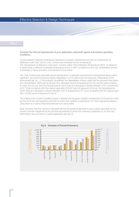
Note, however, that the maximum allowable service temperature depends in many cases essentially on the<br />
duration and the magnitude of the mechanical stresses to which the material is subjected i.e. on the max.<br />
de<strong>for</strong>mation one can allow in a given application [see fi g. 6].<br />
Fig. 6:<br />
Examples of Thermal Per<strong>for</strong>mance<br />
Temperature of defl ection under load<br />
acc. to ISO 75/Method A: 1.8 MPa [°C]<br />
C 450°<br />
400°<br />
350°<br />
300°<br />
250°<br />
200°<br />
150°<br />
100°<br />
50°<br />
0<br />
Ertalon ® 66SA<br />
Nylatron ® NSM<br />
Ertacetal ® C<br />
Ertalyte ®<br />
Fluorosint ® 500<br />
<strong>Quadrant</strong> ® PPSU<br />
Techtron ® HPV PPS<br />
Ketron ® 1000 PEEK<br />
Duratron ® T4203 PAI<br />
Duratron ® CU60 PBI<br />
450° C<br />
400°<br />
350°<br />
300°<br />
250°<br />
200°<br />
150°<br />
100°<br />
50°<br />
0<br />
Max. allowable service temperature in air<br />
continuously <strong>for</strong> min. 20.000 h [°C]<br />
10