Manual instruction - Mass Comparator WPW/KO - RADWAG
Manual instruction - Mass Comparator WPW/KO - RADWAG
Manual instruction - Mass Comparator WPW/KO - RADWAG

You also want an ePaper? Increase the reach of your titles
YUMPU automatically turns print PDFs into web optimized ePapers that Google loves.
<strong>Manual</strong> number:<br />
PTI-33-02/09/08/A<br />
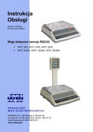
<strong>Mass</strong> <strong>Comparator</strong> <strong>WPW</strong>/<strong>KO</strong><br />
MANUFACTURER OF ELECTRONIC<br />
WEIGHING INSTRUMENTS<br />
<strong>RADWAG</strong> 26 – 600 Bracka 28 Street - POLAND<br />
Radom, phone +48 48 384 88 00, phone/fax +48 48 385 00 10,<br />
Sales Department +4848 366 80 06<br />
www.radwag.com
SEPTEMBER 2008<br />
- 2 -
Table OF CONTENTS<br />
1. I NTENDED USE .......................................................................................................................................7<br />
2. PRECAUTIONARY MEASURES ..............................................................................................................8<br />
3. WARRANTY CONDITIONS ......................................................................................................................8<br />
4. MAIN DIMENSIONS .................................................................................................................................9<br />
5. DESCRIPTON OF CONNECTORS...........................................................................................................9<br />
6. UNPACKING AND MOUNTING..............................................................................................................10<br />
7. GETTING STARTED ..............................................................................................................................11<br />
8. KEYBOARD............................................................................................................................................11<br />
9. PICTOGRAMS........................................................................................................................................11<br />
9.1. Battery charge indication ...............................................................................................................12<br />
10. F UCTIONS OF KEYS............................................................................................................................13<br />
11. MENU - PARAMETERS ........................................................................................................................14<br />
11.1. O verview of parameters...............................................................................................................14<br />
11.2. Navigating within the menu level..................................................................................................17<br />
11.2.1. K eyboard ...........................................................................................................................17<br />
11<br />
.2.2. Quick access .....................................................................................................................18<br />
11.3. Return to weighing.......................................................................................................................18<br />
12. WEIGH<br />
ING ............................................................................................................................................19<br />
12.1. T arring .........................................................................................................................................19<br />
12.2. I nscribing tare value.....................................................................................................................19<br />
12.3. Z eroing ........................................................................................................................................20<br />
12.4. W eighings in two ranges..............................................................................................................21<br />
12.5. Toggling between weight units.....................................................................................................21<br />
12.5.1. S election of basic unit........................................................................................................21<br />
12.5.2. Toggling between weight units...........................................................................................22<br />
12.6. Switching between platforms .......................................................................................................22<br />
13. MAIN P ARAMETERS............................................................................................................................23<br />
13.1. F iltering level ...............................................................................................................................23<br />
13.2. M edian filter.................................................................................................................................24<br />
13.3. D osing filter setting ......................................................................................................................24<br />
13.4. M inimal mass parameter .............................................................................................................26<br />
13.5. T are function................................................................................................................................27<br />
13.6. Autozero ......................................................................................................................................28<br />
14. PORTS PARAMETERS.........................................................................................................................29<br />
14.1. RS 232, RS 485 setting ...............................................................................................................29<br />
14.1.1. B aud rate of RS 232 ..........................................................................................................29<br />
14.1.2. B aud rate of RS 485 ..........................................................................................................30<br />
14.1.3. R S 232 parameters ...........................................................................................................31<br />
14<br />
.1.4. Setting of RS 485 parameters ...........................................................................................32<br />
14.2. ETHERNET setting......................................................................................................................33<br />
15. EXTERNAL DEVICES...........................................................................................................................34<br />
15.1. Cooperation with a computer.......................................................................................................34<br />
15.1.1. S elect the communication port scale-computer .................................................................34<br />
15.1.2. T ype of printout scale – computer......................................................................................35<br />
15.1.3. A ddress setting..................................................................................................................36<br />
15<br />
.1.4. Order operating of communication protocol.......................................................................36<br />
15.2. Cooperation with printers.............................................................................................................37<br />
15<br />
.2.1. Communication port scale - printer....................................................................................37<br />
15.3. Cooperation with a barcode scanner ...........................................................................................38<br />
15.3.1. Select a communication port for the scanner.....................................................................38<br />
15.3.2. Setting the START parameter............................................................................................39<br />
15<br />
.3.3. Setting the LENGTH parameter.........................................................................................40<br />
15.4. Cooperation with a transponder card reader................................................................................40<br />
15.4.1. S electing of communication port........................................................................................41<br />
15<br />
.4.2. Procedure of ascribing card numbers to operators ............................................................41<br />
15.5. Cooperation with an additional display.........................................................................................42<br />
15.5.1. Selecting a communication port.........................................................................................42<br />
15.5.2. Selecting an additional display type...................................................................................43<br />
- 3 -
16. DATE / TIME SETTING .........................................................................................................................44<br />
16.1. T ime view ....................................................................................................................................44<br />
16.2. T ime setting.................................................................................................................................44<br />
16.3. Date format..................................................................................................................................45<br />
17. PRINTOUTS..........................................................................................................................................46<br />
17.1. Printout type ................................................................................................................................46<br />
17.2. P rintout of stable / unstable data .................................................................................................47<br />
17.3. C heckweighing mode ..................................................................................................................48<br />
17.4. N on-standard printouts ................................................................................................................49<br />
17.5. D esigning non-standard printouts ................................................................................................49<br />
17.6. Texts in non-standard printouts ...................................................................................................51<br />
17.6.1. V ariables appearing in all modes.......................................................................................51<br />
17.6.2. V ariables for printing out weighings from the database .....................................................52<br />
17.6.3. V ariables for printouts of reports from weighings...............................................................53<br />
17.6.4. Special characters that can be used in non-standard printouts .........................................54<br />
18. DATAB<br />
ASES.........................................................................................................................................54<br />
18.1. L ogging in....................................................................................................................................54<br />
18.2. Access level.................................................................................................................................56<br />
18.2.1. A ccess level to edition of databases..................................................................................56<br />
18<br />
.2.2. Access level for disabled logging......................................................................................56<br />
18.3. P assword type .............................................................................................................................57<br />
18.4. T ype of codes ..............................................................................................................................58<br />
18.5. Access to edition of databases ....................................................................................................59<br />
18.6. Quick searching in databases......................................................................................................59<br />
18.6.1. Q uick code search.............................................................................................................60<br />
18.6.2. Q uick name search............................................................................................................60<br />
18<br />
.6.3. Quick number search ........................................................................................................61<br />
18.7. U ser database .............................................................................................................................62<br />
18.8. A ssortment database...................................................................................................................64<br />
18.9. Weighings database ....................................................................................................................66<br />
18.10. Database of tare v alues.............................................................................................................67<br />
18.11. General purpose variables.........................................................................................................68<br />
18.11.1. Editing general purpose variables ...................................................................................68<br />
18.11.2. General purpose variables in printouts ............................................................................69<br />
19. REPORTS FROM WEIGHINGS ............................................................................................................70<br />
19.1. E diting reports .............................................................................................................................70<br />
19.2. Printouts of reports ......................................................................................................................71<br />
20. CONFI<br />
GURATION OF EXTERNAL INPUTS / OUTPUTS.....................................................................72<br />
20.1. C onfiguration of external buttons .................................................................................................72<br />
20.2. Configuration of outputs...............................................................................................................73<br />
21. STATIS<br />
TICS..........................................................................................................................................74<br />
21.1. U pdating statistics .......................................................................................................................74<br />
21.2. P rintouts of statistics....................................................................................................................75<br />
21.3. Zeroing statistics..........................................................................................................................76<br />
22. OTHER PARAMETERS ........................................................................................................................77<br />
22.1. Language setting .........................................................................................................................77<br />
22.2. LED power setting .......................................................................................................................77<br />
22.3. W ork modes for LEDs .................................................................................................................78<br />
22.4. A utomatic power down ................................................................................................................80<br />
22.5. Backlight......................................................................................................................................81<br />
22.5.1. B acklight – power supply from mains ................................................................................81<br />
22<br />
.5.2. Backlight - power supply from the accumulator ................................................................82<br />
22.6. “ Beep” sound – key-press reaction ..............................................................................................82<br />
22.7. K eypad modes.............................................................................................................................83<br />
22.8. Software version view..................................................................................................................84<br />
23. SCAL E CALIBRATION .........................................................................................................................84<br />
23.1. C alibration procedure ..................................................................................................................85<br />
23.2. Start mass adjustment.................................................................................................................86<br />
24. WORK MODES .....................................................................................................................................87<br />
24.1. Accessibility of work modes.........................................................................................................87<br />
24.2. Programmable keys.....................................................................................................................88<br />
- 4 -
24.3. + /- control according to an inscribed standard mass....................................................................90<br />
24.4. M aximal force latch......................................................................................................................92<br />
24.5. Counting pieces...........................................................................................................................92<br />
24.5.1. E nabling work modes ........................................................................................................93<br />
24.5.2. S etting standard mass by inscribing the mass of a single piece ........................................93<br />
24<br />
.5.3. Setting the standard mass by declaring the quantity of a sample ......................................94<br />
24.6. Deviation in percents in relation to a standard mass....................................................................95<br />
24.6.1. S tarting weighing in per cents............................................................................................95<br />
24.6.2. Weighing a standard mass ................................................................................................95<br />
24.6.3. Inscribing a standard mass................................................................................................96<br />
24.7. Weighing animals ........................................................................................................................97<br />
24.7.1. W eighing time setting ........................................................................................................97<br />
24.7.2. S tarting the work mode......................................................................................................98<br />
24<br />
.7.3. Procedure of weighing animals..........................................................................................98<br />
24.8. Dosin g .........................................................................................................................................99<br />
24.8.1. D osing mode setting..........................................................................................................99<br />
24.8.2. T ime interval between changing dosage thresholds ........................................................100<br />
24.8.3. T ime interval completing process ....................................................................................100<br />
24.8.4. Mode for OUTPUTS ........................................................................................................101<br />
24.8.5. Tarring mode setting........................................................................................................102<br />
24<br />
.8.6. Starting work modes........................................................................................................102<br />
24.9. Standard deviation for comparator measurements ....................................................................104<br />
24.9.1. S electing the series type..................................................................................................105<br />
24.9.2. D eclaration of the number of measurement series ..........................................................106<br />
24.9.3. R eports from measurement series...................................................................................106<br />
24.9.4. S tarting the operation mode ............................................................................................107<br />
24.9.5. Procedure........................................................................................................................107<br />
25. DIAGRAMS OF CONNECTION CABLES ...........................................................................................110<br />
26. CONNECTORS ...................................................................................................................................112<br />
26.1. I/ O connector.............................................................................................................................112<br />
26.2. RS232, RS485 connector ..........................................................................................................113<br />
27. SPECIFICATION OF ADDITIONAL MODULES..................................................................................114<br />
27.1. Ethernet module - ET.................................................................................................................115<br />
27.1.1. Mounting way in PUE C41H ............................................................................................116<br />
27<br />
.1.2. Drawings of sockets and cables for Ethernet...................................................................118<br />
27.2. Analogue output module............................................................................................................118<br />
27.2.1. T echnical specification ....................................................................................................119<br />
27.2.2. T he way of installing inside PUE C41H...........................................................................119<br />
27.2.3. C onfiguration of work modes of analogue modules .........................................................120<br />
27<br />
.2.4. Connections to AN module ..............................................................................................121<br />
27.3. Relay m odule - PK1...................................................................................................................122<br />
27.3.1. T echnical specification ....................................................................................................122<br />
27.3.2. Installing in PUE C41H indicators....................................................................................122<br />
27.3.3. Drawing of cables and outputs ........................................................................................124<br />
27.4. WE 4 - 4 inputs / 4 outputs module............................................................................................124<br />
27.4.1. T echnical specification ....................................................................................................124<br />
27.4.2. C olours of cables for I/O..................................................................................................125<br />
27<br />
.4.3. Installing method in PUE C41H indicators .......................................................................125<br />
27.5. WE 8 - 8 inputs / 8 outputs module............................................................................................126<br />
27.5.1. T echnical specification ....................................................................................................127<br />
27.5.2. I nstalling method in PUE C41H indicators .......................................................................127<br />
27.5.3. I/ O diagram......................................................................................................................128<br />
27.5.4. Description of input output wires......................................................................................129<br />
27.6. DP1 – module for an additional platform....................................................................................129<br />
27.6.1. T echnical specification ....................................................................................................130<br />
27.6.2. C olours of wires...............................................................................................................130<br />
27.6.3. C onnecting additional platforms.......................................................................................131<br />
27<br />
.6.4. Installing in PUE C41H housing.......................................................................................133<br />
27.7. RS485 led out via RS 1D gland .................................................................................................135<br />
27.7.1. Installing inside the PUE C41H housing ..........................................................................135<br />
27.7.2. RS 485 - PT0012 cable drawing ......................................................................................136<br />
- 5 -
28. COMMUNICATION PROTOCOL ........................................................................................................137<br />
28.1. G eneral information ...................................................................................................................137<br />
28.2. R espond message format..........................................................................................................138<br />
28.3. Command’s description .............................................................................................................138<br />
28.3.1. Z eroing ............................................................................................................................138<br />
28.3.2. T arring .............................................................................................................................139<br />
28.3.3. Send the stable result in basic unit ..................................................................................139<br />
28.3.4. Send the result immediately in basic unit.........................................................................140<br />
28.3.5. S end the stable result in current unit ...............................................................................140<br />
28.3.6. S end the result immediately in current unit......................................................................141<br />
28.3.7. S witch on continuous transmission in basic unit ..............................................................141<br />
28.3.8. S witch off continuous transmission in basic unit..............................................................142<br />
28.3.9. Switch on continuous transmission in current unit ...........................................................142<br />
28.3.10. S witch off continuous transmission in current unit .........................................................142<br />
28.3.11. L ock the scale keyboard................................................................................................143<br />
28.3.12. U nlock the scale keyboard ............................................................................................143<br />
28.3.13. Initiating of dosing/filling ................................................................................................143<br />
28.3.14. Stop of dosing/filling ......................................................................................................143<br />
28.3.15. S et lower threshold........................................................................................................143<br />
28.3.16. S et upper threshold .......................................................................................................144<br />
28.3.17. R ead lower threshold.....................................................................................................144<br />
28.3.18. R ead upper threshold ....................................................................................................144<br />
28<br />
.3.19. Send all implemented commands..................................................................................145<br />
28.4. M anual printouts / automatic printouts .......................................................................................145<br />
28.5. C ontinuous transmission ...........................................................................................................146<br />
28.6. Configuring printouts..................................................................................................................146<br />
29. E RROR MESSAGES...........................................................................................................................147<br />
30. T ROUBLE SHOOTING .......................................................................................................................147<br />
31. TECHNICAL PARAMETERS ..............................................................................................................148<br />
- 6 -
1. INTENDED USE<br />
<strong>Mass</strong> comparators are devices designed for determining the differences<br />
between masses of calibration weight (B) and reference weight (A).<br />
<strong>Comparator</strong>s are most often used in measuring laboratories for<br />
calibration of weights and masses. Radwag offers comparators<br />
designed for calibration of weights and masses class M1<br />
according to OIML R111.<br />
Functions:<br />
• Tarring within the whole measuring range,<br />
• Inscribing tare value,<br />
• Automatic tare,<br />
• Automatic print,<br />
• Continuous transmission,<br />
• Printout configuration (stable/immediate),<br />
• Designing printouts,<br />
• Minima mass,<br />
• Force measurements in Newtons,<br />
• Cooperation with computers,<br />
• Cooperation with printers,<br />
• Cooperation with external industrial buttons ZERO, TARA, PRINT,<br />
• Cooperation with a barcode scanner,<br />
• Cooperation with a transponder card reader,<br />
• Totalizing,<br />
• +/- control (checkweighing),<br />
• Deviation in percents,<br />
• Top mass latch,<br />
• Dosing,<br />
• Counting pieces,<br />
• Weighings animals,<br />
• Calculating standard deviation for weighings.<br />
User functions may have attribute of accessibility. For this reason it is<br />
possible to adjust scale to individual needs to provide access to only these<br />
functions which are currently needed. Attribute determination accessible /<br />
inaccessible is possible in user menu and described in further part of<br />
manual.<br />
- 7 -
2. PRECAUTIONARY MEASURES<br />
A. Please, read carefully this user manual before and use the device<br />
according to its intended use;<br />
B. If the device is about to operate in a strong electrostatic field<br />
(e.g. printing houses etc.) it should be connected to the earthing.<br />
Connect it to the clamp terminal signed ;<br />
C. Devices that are to be withdrawn from usage should be sent back to<br />
the producer or in case of own utilization do it according to the law.<br />
3. WARRANTY CONDITIONS<br />
A. <strong>RADWAG</strong> is obliged to repair or change those elements that<br />
appears to be faulty because of production and construction reason,<br />
B. Defining defects of unclear origin and outlining methods of<br />
elimination can be settled only in participation of a user and<br />
the manufacturer representatives,<br />
C. <strong>RADWAG</strong> does not take any responsibility connected with<br />
destructions or losses derives from non-authorized or inappropriate<br />
(not adequate to manuals) production or service procedures,<br />
D. Warranty does not cover:<br />
• Mechanical failures caused by inappropriate maintenance of<br />
the device or failures of thermal or chemical origin or caused<br />
by atmospheric discharge, overvoltage in mains or other<br />
random event,<br />
• Inappropriate cleaning.<br />
E. Loss of warranty appears after:<br />
• Access by an unauthorized service,<br />
• Intrusion into mechanical or electronic construction<br />
of unauthorized people,<br />
• Removing or destroying protection stickers.<br />
F. The detailed warranty conditions one can find in warranty certificate.<br />
G. Contact with the central authorized service:<br />
+48 48 384 88 00 ext. 106 or 107.<br />
- 8 -
4. MAIN DIMENSIONS<br />
Main dimensions of PUE C41H<br />
5. DESCRIPTON OF CONNECTORS<br />
Terminal connectors<br />
1 – I/O connectors<br />
2 – RS232, RS485 connector<br />
3 – Tensometer gland<br />
4 – Power supply gland<br />
5 – Earthing terminal<br />
6 – Additional platform gland (option)<br />
7 –Ethernet gland (option)<br />
8 – analogue output gland - voltage or current loop (option)<br />
- 9 -
Caution:<br />
In accordance to the number of mounted modules the number and the<br />
placement of glands and connectors can vary. Connectors and glands<br />
mentioned in the standard solution appears in every option in the same<br />
place regardless of the option.<br />
6. UNPACKING AND MOUNTING<br />
Before using the scale remove the transport protections (if installed):<br />
Then screw in levelling feets on the mandrels that protrude from load cells:<br />
Place the scale on the spot of use on the flat, stable ground far away from<br />
sources of heat. The platform should be levelled out by putting pads under<br />
feet and the use of an external level device.<br />
Every foot can be screwed in or out. This way only a smal range of level<br />
regulation is achievable. Basic levelling should be performed by putting<br />
steel pads under legs and observing the level on external level device<br />
- 10 -
7. GETTING STARTED<br />
• Switch off the scale using – keep pressing it for about 0.5 sec,<br />
• Wait for the test completion,<br />
• Then you will see zero indication and following pictograms displayed:<br />
kg<br />
- zero<br />
- equilibrium<br />
- weight unit<br />
If the indication is not zero – press zero button.<br />
8. KEYBOARD<br />
9. PICTOGRAMS<br />
No Pictogram Description<br />
1. Zero indication (Autozero zone)<br />
2. Equilibrium<br />
3. kg (g) Weighing mode<br />
4. Battery/accumulator<br />
- 11 -
5. Net Tare has been introduced<br />
6. Min Lower threshold<br />
7. OK Proper mass<br />
8. Max Upper threshold or TOP mode<br />
9. Counting pieces<br />
10. % Weighings in percents<br />
11. ► Animals weighings<br />
12.<br />
►<br />
►<br />
13. Dosing<br />
14. | ------ | Bargraph<br />
15. First platform<br />
16. Second platform<br />
Standard deviation mode for the comparator<br />
17. Second range of weightings’<br />
9.1. Battery charge indication<br />
pictogram is situated in the upper right corner informed about the<br />
discharge level or charging process:<br />
• pictogram blinks: accumulator damaged or no accumulator,<br />
• pictogram displayed continuously: it is charge between<br />
70% and100%,<br />
• pictogram displayed continuously: it is charge between<br />
30% and70%,<br />
• pictogram displayed continuously: it is discharge<br />
(less than 30%), connect to the mains to charge,<br />
• Internal elements of<br />
charging,<br />
• No<br />
pictograms are displayed in sequence:<br />
pictogram: power supply from mains, battery charges.<br />
- 12 -
10. FUCTIONS OF KEYS<br />
Keys<br />
Description<br />
Turning on/off the scale<br />
Toggling between weight units<br />
Changing active platform<br />
Inscribing tare value<br />
Zeroing<br />
Tarring<br />
Function key (entering the menu)<br />
Leaving a function without saving or reaching<br />
a higher level of the menu<br />
Printing out the result or confirming some entered data<br />
Selection / viewing of articles from<br />
the assortment database<br />
Selection purpose variables<br />
…<br />
N/A<br />
Work mode selection<br />
N/A<br />
Log out<br />
Inscribing MIN, MAX thresholds<br />
View of statistics<br />
…<br />
…<br />
N/A<br />
Programmable keys<br />
- 13 -
Caution:<br />
After pressing , functions of keys change while in the menu.<br />
The way of using them is described farther.<br />
11. MENU - PARAMETERS<br />
11.1. Overview of parameters<br />
The menu has been divided into 10 basic groups. Each group has its<br />
individual name starting with the capital letter P. Names of groups<br />
and their contents are shown below.<br />
PARAMETERS<br />
P 1 SCALE PARAMETERS<br />
P 1.1 PLATFORM 1 PAR.<br />
P 1.1.1 FITER | AVERAGE<br />
P 1.1.2 MED. FILTER | YES<br />
P 1.1.3 LO THRESH. | 20 d<br />
P 1.1.4 TARE MODE | STDRD<br />
P 1.1.5 START UNIT | kg<br />
P 1.1.6 AUTOZERO | YES<br />
P 1.1.7 DOS. FILTER | 1<br />
P 1.2 PLATFORM 2 PAR.<br />
P 1.2.1 FITER | AVERAGE<br />
P 1.2.2 MED. FILTER | YES<br />
P 1.2.3 LO THRESH. | 20 d<br />
P 1.2.4 TARE MODE | STDRD<br />
P 1.2.5 BASIC UNIT | kg<br />
P 1.2.6 AUTOZERO | YES<br />
P 1.2.7 DOS. FILTER | 1<br />
P 1.3 FACTORY NO | 0<br />
P 2 COM PORTS PARAMETERS<br />
P 2.1 RS 485<br />
P 2.1.1 BAUD RATE | 9600<br />
P 2.1.2 DATA BITS | 8<br />
P 2.1.3 PARITY BIT | NO<br />
P 2.1.4 STOP BITS | 1<br />
P 2.2 RS 232 (1)<br />
P 2.2.1 BAUD RATE | 9600<br />
P 2.2.2 DATA BITS | 8<br />
P 2.2.3 PARITY BIT | NO<br />
P 2.2.4 STOP BITS | 1<br />
P 2.3 RS 232 (2)<br />
P 2.3.1 BAUD RATE | 9600<br />
P 2.3.2 PARITY BIT | NO<br />
- 14 -
P 2.4 ETHERNET<br />
P 2.4.1 COMM MODE | SERVER<br />
P 2.4.2 IP ADDRESS | 192.168.0.2<br />
P 2.4.3 SUBNET MSK. | 255.255.255.0<br />
P 2.4.4 GATEWAY | 192.168.0.1<br />
P 2.4.5 LOCAL PORT | 4001<br />
P 2.4.6 HOST IP | 192.168.0.3<br />
P 2.4.7 HOST PORT | 2000<br />
P 2.4.8 TIMEOUT | 60<br />
P 3 DEVICES<br />
P 3.1 COMPUTER<br />
P 3.1.1 COMP. PORT | NO<br />
P 3.1.2 ADDRESS | 1<br />
P 3.1.3 COMP. PRINT | NONE<br />
P 3.1.4 BASIC TRS. | YES<br />
P 3.2 PRINTER<br />
P 3.2.1 PRINT PORT | NO<br />
P 3.3 BARCODE SCANNER<br />
P 3.3.1 BARCOD. COM | NO<br />
P 3.3.2 START | 0<br />
P 3.3.3 LENGTH | 0<br />
P 3.4 TRANSP. CARD READER<br />
P 3.4.1 READER COM | NO<br />
P 3.5 ADDITIONAL DISPLAY<br />
P 3.5.1 DISPL. PORT | NO<br />
P 3.5.2 DISPL. TYPE | LCD<br />
P 4 DATE / TIME<br />
P 4.1 DISPL. TIME | * FUNCTION *<br />
P 4.2 SET TIME | * FUNCTION *<br />
P 4.3 DAT. FORMAT | YY-MM-DD<br />
P 5 PRINTOUTS<br />
P 5.1 AUTO. PRINT | WHEN STAB<br />
P 5.2 STAB. PRINT | YES<br />
P 5.3 CHECKWEIGHING | NO<br />
P 5.4 PRINTOUT | STANDARD<br />
P 5.5 PRINTOUT 1 | * FUNCTION *<br />
P 5.6 PRINTOUT 2 | * FUNCTION *<br />
P 5.7 PRINTOUT 3 | * FUNCTION *<br />
P 5.8 PRINTOUT 4 | * FUNCTION *<br />
P 6 DATABASES<br />
P 6.1 LOGGING | NO<br />
P 6.2 EDITION | ADMIN<br />
P 6.3 ANON. ACC. | ADMIN<br />
P 6.4 PASS. TYPE | NUM<br />
P 6.5 CODE TYPE | NUM<br />
P 6.6 STATISTICS | GENERAL<br />
P 7 WORK MODES<br />
P 7.1 MODE ACCES.<br />
- 15 -
P 7.1.1 WEIGHING | YES<br />
P 7.1.2 TOP | YES<br />
P 7.1.3 COUN. PCS | YES<br />
P 7.1.4 CHECKWEIGH. | YES<br />
P 7.1.5 ANIM. WEIGH. | YES<br />
P 7.1.6 DOSAGE | YES<br />
P 7.1.7 ODCH. STAND. | YES<br />
P 7.2 BUTTONS FUNCTIONS<br />
P 7.2.1 B6 | NONE<br />
P 7.2.2 B7 | NONE<br />
P 7.2.3 B8 | NONE<br />
P 7.2.4 B9 | NONE<br />
P 7.2.5 B0 | NONE<br />
P 7.3 ANIM. WEIGH.<br />
P 7.3.1 WEIGH. TIME | 15<br />
P 7.4 DOSAGE<br />
P 7.4.1 DOSING NAM. | 1<br />
P 7.4.2 DELAY | 5<br />
P 7.4.3 CHUTE TIME | 5<br />
P 7.4.4 OUTPUT MOD. | 1_2<br />
P 7.4.5 TARRING | NO<br />
P 7.5 ODCH. STAND.<br />
P 7.5.1 METHOD | ABBA<br />
P 7.5.2 NO OF WEIGHINGS | 3<br />
P 7.5.3 AUTO-RAPORT | NO<br />
P 8 I/O CONFIG<br />
P 8.1 EXTERNAL BUTTONS<br />
P 8.1.1 TARE BUTT. | NO<br />
P 8.1.2 PRINT BUTT. | NO<br />
P 8.1.3 ZERO BUTT. | NO<br />
P 8.1.4 START BUTT. | NO<br />
P 8.1.5 STOP BUTT. | NO<br />
P 8.1.6 EXT. START | NO<br />
P 8.1.7 TERM. BUTT. | NO<br />
P 8.1.8 CHUTE PERM. | NO<br />
P 8.2 OUTPUT CONF.<br />
P 8.2.1 MIN | NO<br />
P 8.2.2 OK | NO<br />
P 8.2.3 MAX | NO<br />
P 8.2.4 STABLE | NO<br />
P 8.2.5 THRESH 1 | NO<br />
P 8.2.6 THRESH 2 | NO<br />
P 8.2.7 CHUTE | NO<br />
P 9 OTHER<br />
P 9.1 LANGUAGE | ENGLISH<br />
P 9.2 DIODES<br />
P 9.2.1 LED POWER | 100%<br />
P 9.2.2 RED DIODES | NON-STAB.<br />
P 9.2.3 GREEN DIOD. | STABLE<br />
P 9.3 POWER SAVE | NO<br />
- 16 -
P 9.4 BACKLIGHT<br />
P 9.4.1 BL MAINS | YES<br />
P 9.4.2 BL BATTER. | 100%<br />
P 9.5 BEEP | YES<br />
P 9.6 KEYPAD TYPE | ABC2<br />
P 9.7 SOFT. VER. | WTLS 1.5.3<br />
P 10 USER CALIB.<br />
P 10.1 PLATF. 1 CALIB<br />
P 10.1.1 STRT M. ADJ. | * FUNCTION *<br />
P 10.1.2 CALIBRATION | * FUNCTION *<br />
P 10.2 PLATF. 2 CALIB<br />
P 10.2.1 STRT M. ADJ | * FUNCTION *<br />
P 10.2.2 CALIBRATION | * FUNCTION *<br />
11.2. Navigating within the menu level<br />
Use keyboard to browse the menu.<br />
11.2.1. Keyboard<br />
Entering the main menu, special characters in the editing field<br />
Moving up (left)<br />
Moving down (right)<br />
Adding records in a database<br />
Adding characters in an editing field<br />
Clearing the editing field<br />
Erasing a record in a database<br />
Selecting and editing general purpose variables<br />
START of dosing procedure<br />
START of weighings animals<br />
Deleting characters in editing field<br />
Clearing editing field<br />
Deleting database<br />
Zeroing statistics<br />
Entering submenus<br />
Entering parameters<br />
Confirming changes<br />
Skipping changes<br />
Leaving the menu level<br />
Starting the next cycle of calculating the standard deviation<br />
- 17 -
11.2.2. Quick access<br />
It is possible to move quickly within the parameters’ menu using<br />
to .<br />
Procedure:<br />
11.3. Return to weighing<br />
Press<br />
, until you see SAVE CHANGES ?. Then you press:<br />
– confirms changes or – skips changes. Then the<br />
scale returns to weighing.<br />
- 18 -
12. WEIGHING<br />
Put a load on the pan. When<br />
displays, you can read the measurement.<br />
12.1. Tarring<br />
In order to determine the net mass put the packaging on the pan.<br />
After stabilising press - (Net pictogram will be displayed in the<br />
left upper corner and zero will be indicated).<br />
After placing a load on the weight pan net mass will be shown.<br />
Tarring is possible within the whole range of the scale. After<br />
unloading the pan the display shows the tarred value with<br />
minus sign.<br />
Caution:<br />
Tarring cannot be performer when a negative or zero value<br />
is being displayed. In such case Err3 appears on the display<br />
and a short beep sound will be emitted.<br />
12.2. Inscribing tare value<br />
You can also inscribe a tare value:<br />
Procedure:<br />
While in weighings mode:<br />
• Press ,<br />
• In the lower line you will see an editing field:<br />
- 19 -
• Inscribe the tare value:<br />
• Press ,<br />
• The scale return to weighings mode The inscribed tare value<br />
can be seen on the display with „–” sign.<br />
Tare can be inscribed anytime in weighings mode.<br />
12.3. Zeroing<br />
To ZERO the scale press: .<br />
The scale will display zero and following pictograms: and .<br />
Zeroing is only possible within the scope of ±2% of full scale.<br />
While zeroing outside the scope of ±2% you will see Err2.<br />
Zeroing is possible only in stable state.<br />
Caution:<br />
Zeroing is possible only within ±2% of full range around zero. If the zeroed<br />
value is beyond the interval of ±2%, Err2 is displayed and a short beep<br />
sound will be emitted.<br />
- 20 -
12.4. Weighings in two ranges<br />
Switching between the I range and the II range happens automatically<br />
(exceeding Max of the I range).<br />
Weighings in the second range is signalled by a pictogram in the top left<br />
corner of the display.<br />
Then weighings is done with the accuracy of the II range to the moment<br />
of returning to zero (autozero range ) where the scale switches back<br />
to the I range.<br />
12.5. Toggling between weight units<br />
12.5.1. Selection of basic unit<br />
This function sets the unit that will be set after powering on.<br />
Procedure:<br />
• While In weighings mode press<br />
and then:<br />
- 21 -
Selection:<br />
• When the main unit is [kg], users can select among:<br />
[kg, lb, oz, ct, N, g] , for verified scales [lb, oz, N]<br />
are not accessible;<br />
• When the main unit is [g], users can select among:<br />
[g, kg, lb, oz, ct, N] , for verified scales [lb, oz, N]<br />
are not accessible.<br />
12.5.2. Toggling between weight units<br />
Press the Units key to toggle between weight units.<br />
Accessible units:<br />
• When [kg] is the basic unit, users can toggle between:<br />
[kg, lb, oz, ct, N, g]. For verified scales [lb, oz, N]<br />
are not accessible;<br />
• When [g], is the basic unit, users can toggle between:<br />
[g, kg, lb, oz, ct, N] For verified scales [lb, oz, N]<br />
are not accessible.<br />
Notice:<br />
The terminal always starts working with the main (calibration) unit.<br />
12.6. Switching between platforms<br />
If a scale is equipped with two platforms press to change the<br />
platform. The active platform is signalled by pictograms in the top<br />
left corner of the display.<br />
- 22 -
13. MAIN PARAMETERS<br />
Users can adjust the scale to external ambient conditions (filtering level)<br />
or particular needs (autozero operation, tare memory). This parameters<br />
are present in .<br />
13.1. Filtering level<br />
Procedure:<br />
• Enter and then:<br />
Return to weighing:<br />
See 11.3.<br />
Notice:<br />
The higher filtering level the longer stabilization time.<br />
- 23 -
13.2. Median filter<br />
This filter eliminates short mechanical shocks.<br />
Procedure:<br />
• Enter and then:<br />
Return to weighing:<br />
See 11.3.<br />
NO - filter disabled<br />
YES - filter enabled<br />
13.3. Dosing filter setting<br />
In PUE 41 terminals an special averaging filter for dosing process has<br />
been implemented. The result of this filtration, instead of traditional filters<br />
for static weighing, is compared with dosing setpoints. The filter parameter<br />
is the number of samples from the A/D converter (1 to 10). When the filter<br />
is set to 1 every reading from the A/D converter is compared with the<br />
dosing setpoints, which does not introduce any delay. If the filter<br />
parameter is set to n>1, the filtering result will be calculated as<br />
an arithmetic average from the last n measurements.<br />
n<br />
X i<br />
i=<br />
1<br />
∑<br />
M = ,where M is a filtering result from samples X 1 to X n .<br />
- 24 -
As dosing is a kind of dynamic state, which results in continuous changes<br />
in measurements, the averaged number of samples in the filter have an<br />
effect on the result. An example situation is illustrated below:<br />
The upper blue line represents results for n=1 samples in the filter buffer<br />
(averaging is off). The lower red line represents the same process when<br />
the filter is set to n=10. The difference depends on the dynamics (dosing<br />
rate) of changes either. The theory shows that the best filter parameter is<br />
n=1 because the setpoints can be compared with the current dosed mass.<br />
But in practice, there is a noise from different vibration sources registered<br />
and sometimes external forces connected with kinetic and potential<br />
energy of the poured material. It causes that the filter setting should<br />
be matched experimentally.<br />
Caution:<br />
1. The subsequent readouts of the measured value from<br />
the A/D converter is performed every 100 ms.<br />
2. This filter operates only in dosing procedures.<br />
- 25 -
Procedure:<br />
• Enter according<br />
to 11.2. of the manual:<br />
Return to weighing:<br />
See 11.3.<br />
13.4. Minimal mass parameter<br />
Parameter PROG LO is related to following functions:<br />
- automatic tare,<br />
- automatic operation,<br />
- weighing animals.<br />
The next automatic tarring can be performed after the indication reaches<br />
the gross value below LO THRESH.<br />
For automatic weighing the next weighings can be performed after the<br />
indication reaches the net value below LO THRESH.<br />
The procedure of weighing animals will start after the gross animal mass<br />
is greater than LO THRESH.<br />
Procedure:<br />
• Enter according to 11.2. and then:<br />
- 26 -
Return to weighing:<br />
See 11.3.<br />
13.5. Tare function<br />
This parameter allows to set appropriate parameters for tarring.<br />
Procedure:<br />
• Enter according to 11.2. and then:<br />
- 27 -
AUTO - disable automatic tare (the mode is remembered after<br />
restart);<br />
NORMAL - tarring by pressing ;<br />
MEMORY - tare memory mode - the last tare value is being kept in<br />
a non-volatile memory, Net pictogram is displayed.<br />
SUM - sum of tares – summing up a product tare value with<br />
a tare from the database of tare values or with an<br />
inscribed one.<br />
Return to weighing:<br />
See 11.3.<br />
13.6. Autozero<br />
The autozero function has been implemented in order to assure precise<br />
indications. This function controls and corrects „0” indication. While the<br />
function is active it compares the results continuously with constant<br />
frequency. If two sequentional results differ less than the declared<br />
value of autozero range, so the scale will be automatically zeroed<br />
and the pictograms and will be displayed.<br />
When AUTOZERO is disabled zero is not corrected automatically.<br />
However, in particular cases, this function can disrupt the measurement<br />
process e.g. slow pouring of liquid or powder on the weighing pan.<br />
In this case, it is advisable to disable the autozero function.<br />
Procedure:<br />
• Enter according to 11.2. and then:<br />
- 28 -
Return to weighing:<br />
See 11.3.<br />
NO - Autozero disabled<br />
YES - Autozero enabled<br />
14. PORTS PARAMETERS<br />
It is possible to connect external devices (printer, computer) to the ports:<br />
• RS 232 (1)<br />
• RS 232 (2)<br />
• RS 485<br />
• Ethernet<br />
Configuration can be done in: .<br />
14.1. RS 232, RS 485 setting<br />
For setting: RS 232, RS 485 use following parameters:<br />
• Baud rate<br />
- 2400 - 115200 bit / s<br />
• Data bits - 7, 8<br />
• Stop bit - 1, 1.5, 2<br />
• Parity<br />
- NONE, ODD, EVEN<br />
Caution:<br />
There is impossible to set data bits and stop bits for RS 232(2).<br />
They are internally set to 8 bits and 1 stop bit.<br />
14.1.1. Baud rate of RS 232<br />
Procedure:<br />
• Enter according<br />
to 11.2. and then:<br />
- 29 -
Return to weighing:<br />
See 11.3.<br />
14.1.2. Baud rate of RS 485<br />
Procedure:<br />
• Enter < P2 COM PORTS PARAMETERS > according<br />
to 11.2. and then:<br />
Return to weighing:<br />
See 11.3.<br />
- 30 -
14.1.3. RS 232 parameters<br />
Procedure:<br />
• Enter and press ,<br />
• Using scroll to and press :<br />
• The selected value confirm with ,<br />
• Using go to and press :<br />
• The selected value confirm with ,<br />
• Using go to and press :<br />
• The selected value confirm with ,<br />
Return to weighing:<br />
See 11.3.<br />
- 31 -
14.1.4. Setting of RS 485 parameters<br />
Procedure:<br />
• Enter and press ,<br />
• Using go to and press :<br />
• The selected value confirm with ,<br />
• Using go to and press :<br />
• The selected value confirm with ,<br />
• Using go to and press :<br />
• The selected value confirm with ,<br />
Return to weighing:<br />
See 11.3.<br />
- 32 -
14.2. ETHERNET setting<br />
ETHERNET can be configured in .<br />
Inventory of default parameters:<br />
No NAME VALUE DESCRIPTION<br />
P2.4.1 WORK MODE SERVER, CLIENT<br />
Ethernet connection as Server or Client.<br />
SERVER – scale waits for connection<br />
CLIENT – scale initiates the connection<br />
to a HOST.<br />
P2.4.2 IP ADDRESS 192.168.0.2 Setting an IP address.<br />
P2.4.3 SUBNET MASK 255.255.255.0<br />
P2.4.4 GATEWAY 192.168.0.1<br />
P2.4.5 LOCAL PORT 4001<br />
P2.4.6 HOST IP 192.168.0.3<br />
P2.4.7 HOST PORT 2000<br />
P2.4.8 TIMEOUT 60<br />
Setting a subnet mask for Ethernet<br />
connection.<br />
Setting a gateway for Ethernet<br />
connection.<br />
Setting a local port for Ethernet<br />
connection. Only for devices that<br />
work as SERVER. Servers waits<br />
for connection on the specified port.<br />
Setting a host IP address (IP of a device<br />
to connect with). Applicable only for<br />
devices configured as CLIENTs.<br />
Setting a Host port (a port for connection<br />
with a computer). Applicable only for<br />
devices configured as CLIENTs.<br />
Time (in seconds) after which noneactive<br />
Ethernet connection is being<br />
broken. Set to 0 to stop breaking the<br />
connection.<br />
Caution:<br />
1. For appropriate setting of: ,<br />
, contact<br />
the supervisor of the net to connect with;<br />
2. The scale does not allow the automatic fetch of net<br />
configuration from DHCP servers.<br />
- 33 -
Return to weighing:<br />
See 11.3.<br />
15. EXTERNAL DEVICES<br />
15.1. Cooperation with a computer<br />
<strong>WPW</strong> scales can cooperate with computers of IBM PC class.<br />
In submenu you can configure interfaces.<br />
<strong>WPW</strong> scales can cooperate with the EDYTOR <strong>WPW</strong> program. The<br />
indicator window reflects the view of a typical indicator display with all<br />
necessary pictograms. The program allows to configure a scale easily,<br />
design printout patterns, supervise databases, set parameters, collect<br />
and save printouts etc.<br />
Caution:<br />
Installation version of EDYTOR <strong>WPW</strong> is accessible on the Internet:<br />
www.radwag.com. Look up: Products / Measuring indicators / PUE C41H.<br />
15.1.1. Select the communication port scale-computer<br />
The computer can be connected to:<br />
• RS 232 (1)<br />
• RS 232 (2)<br />
• RS 485<br />
• Ethernet<br />
Procedure:<br />
• Enter according to 11.2. and then:<br />
- 34 -
Caution:<br />
Standard scales can communicate with computers only via RS232(1)<br />
or RS485.<br />
Return to weighing:<br />
See 11.3.<br />
15.1.2. Type of printout scale – computer<br />
Procedure:<br />
• Enter according to 11.2. and then:<br />
- 35 -
Caution:<br />
The procedure of designing non-standard printouts is described<br />
in chapter 17.6 of this manual.<br />
Return to weighing:<br />
See 11.3.<br />
15.1.3. Address setting<br />
Procedure:<br />
• Enter < P3.1 COMPUTER > according to 11.2. and then:<br />
• Inscribe a value (0 to 254) and press .<br />
Return to weighing:<br />
See 11.3.<br />
15.1.4. Order operating of communication protocol<br />
User in parameter has possibility to set<br />
communication protocol designed to communicate between<br />
<strong>RADWAG</strong> scale and external device.<br />
- 36 -
Procedure:<br />
• Enter < P3.1 COMPUTER > according to 11.2. and then:<br />
Return to weighing:<br />
See 11.3.<br />
15.2. Cooperation with printers<br />
Press to send the current measurement together with the<br />
weighing unit to a printer.<br />
15.2.1. Communication port scale - printer<br />
Following ports can be used:<br />
• RS 232 (1)<br />
• RS 232 (2)<br />
• RS 485<br />
Procedure:<br />
• Enter and then:<br />
- 37 -
Return to weighing:<br />
See 11.3.<br />
15.3. Cooperation with a barcode scanner<br />
The scale gives possibility to cooperate with barcode scanners.<br />
It is used for quick search of database of assortment.<br />
Caution:<br />
In set the baud rate for the<br />
same as your barcode scanner requires (default 9600b/s).<br />
15.3.1. Select a communication port for the scanner<br />
Procedure:<br />
• Enter and then select<br />
a communication port with the barcode scanner:<br />
- 38 -
Return to weighing:<br />
See 11.3.<br />
15.3.2. Setting the START parameter<br />
Procedure:<br />
• Enter and then set the START<br />
parameter – a character number in barcodes that is to be<br />
analysed during the assortment database search:<br />
- 39 -
Return to weighing:<br />
See 11.3.<br />
15.3.3. Setting the LENGTH parameter<br />
Procedure:<br />
• Enter and then set the LENGTH<br />
parameter – the number if character in barcodes (counting from<br />
START) that is to be analysed during the assortment database<br />
search:<br />
Return to weighing:<br />
See 11.3.<br />
15.4. Cooperation with a transponder card reader<br />
Operators can be logged in after powering up the device or previous<br />
logging out by:<br />
• Inscribing a password using the scale keyboard,<br />
• Using transponder cards to log in.<br />
- 40 -
Caution:<br />
In parameters set the baud rate<br />
for the one that requires the barcode scanner (default 9600b/s).<br />
15.4.1. Selecting of communication port<br />
In parameters and then<br />
select a communication port with the transponder card reader:<br />
Return to weighing<br />
See 11.3.<br />
15.4.2. Procedure of ascribing card numbers to operators<br />
In order to log in using a transponder card you need to have it previously<br />
ascribed to a specific operator.<br />
Procedure:<br />
• Connect a transponder card reader to RS232/RS485 on the back<br />
wall of the terminal,<br />
• Select a communication port (see 15.4.1),<br />
- 41 -
• In parameters set the<br />
baud rate (default 9600b/s).<br />
• Enter the database of operators and then find and edit the<br />
required operator. Find field:<br />
• Approaching a card to the reader results in displaying the card<br />
number in the field,<br />
• Press<br />
to confirm,<br />
• Return to weighing – chapter 11.3.<br />
15.5. Cooperation with an additional display<br />
15.5.1. Selecting a communication port<br />
Additional displays can be connected to:<br />
• RS 232 (1)<br />
• RS 232 (2)<br />
• RS 485<br />
Procedure:<br />
• Enter < P3.5 ADDITIONAL DISPLAY > according to 11.2. and then:<br />
- 42 -
Return to weighing:<br />
See 11.3.<br />
15.5.2. Selecting an additional display type<br />
Procedure:<br />
• Enter < P3.5 ADDITIONAL DISPLAY > according to 11.2. and then:<br />
Return to weighing:<br />
See 11.3.<br />
- 43 -
16. DATE / TIME SETTING<br />
Enter to set these parameters.<br />
16.1. Time view<br />
Procedure:<br />
Return to weighing:<br />
See 11.3.<br />
16.2. Time setting<br />
Procedure<br />
• Enter the DATE / TIME> and then:<br />
- 44 -
• After pressing<br />
you will see:<br />
• Enter an appropriate value and confirm it with ,<br />
• You will have to enter the following variables in sequence:<br />
- MONTH<br />
- DAY<br />
- HOUR<br />
- MINUTE<br />
• After confirming the last value with<br />
date and time:<br />
you will see the current<br />
Return to weighing:<br />
See 11.3.<br />
16.3. Date format<br />
Date can be displayed in different format.<br />
Procedure:<br />
• Enter and proceed as follows:<br />
- 45 -
Return to weighing:<br />
See 11.3.<br />
YY - MM - DD - year - month – day<br />
YY - DD - MM - year - day - month<br />
DD - MM - YY - day - month - year<br />
17. PRINTOUTS<br />
17.1. Printout type<br />
Setting the parameter can set a type of printout:<br />
Procedure:<br />
• Enter according to 11.2. and then:<br />
- 46 -
NO - manual printout<br />
WHEN STB - automatic printout after stabilising<br />
CONTIN. - continuous printouts<br />
LAST STB - printing the last stable result after taking<br />
of a load, before reaching the LO-. value<br />
ONE PRINT - Single print over -LO-<br />
Return to weighing:<br />
See 11.3.<br />
17.2. Printout of stable / unstable data<br />
Enter , to set the printout as:<br />
• Stable data,<br />
• Immediate data.<br />
Procedure:<br />
• Enter according to 11.2. and then:<br />
- 47 -
Return to weighing:<br />
See 11.3.<br />
Notice:<br />
In case of verified scales is not accessible for users.<br />
17.3. Checkweighing mode<br />
In this mode printout is possible only when the result is between<br />
Min, Max thresholds.<br />
Procedure:<br />
• Enter according to 11.2. and then:<br />
Return to weighing:<br />
See 11.3.<br />
- 48 -
17.4. Non-standard printouts<br />
Users have possibility to design non-standard printouts<br />
in .<br />
Procedure:<br />
• Enter according to 11.2. and then:<br />
Return to weighing:<br />
See 11.3.<br />
17.5. Designing non-standard printouts<br />
To create a non-standard printout:<br />
• Enter according to 11.2. and then:<br />
- 49 -
• After pressing<br />
to accept your data.<br />
, you will see a cursor. Software is ready<br />
Non-standard printout can comprise:<br />
• Constant texts,<br />
• Variables from different work modes (mass, date, thresholds etc.),<br />
• Non-standard printout design can include max. 320 characters,<br />
• Non-standard printout sent to a printer can include max. 640<br />
characters,<br />
• Up to 4 non-standard printouts can be designed.<br />
Caution:<br />
During designing non-standard printouts all special characters<br />
like CRLF, tabulators etc. have to be added.<br />
Example:<br />
„<strong>RADWAG</strong>”<br />
DATE:<br />
TIME:<br />
MASS:<br />
SIGNATURE:.........<br />
After entering the non-standard printouts edition (see ch. 17.5.)<br />
we design the printout:<br />
„ R A D W A G ” \ C \ T D A T E : % 0 0 2 \ C \ T T I M E : % 0 0 3 \ C \ T<br />
M A S S : % 0 0 0 \ C \ C \ T \ T S I G N A T U R E : . . . . . . . . . . \ C \ 0<br />
- 50 -
17.6. Texts in non-standard printouts<br />
17.6.1. Variables appearing in all modes<br />
CODE<br />
DESCRIPTION<br />
000 <strong>Mass</strong> in a basic unit of the active platform<br />
001 <strong>Mass</strong> in a current unit of the active platform<br />
002 Date<br />
003 Time<br />
004 Date and time<br />
005 Calibration unit<br />
006 Current unit<br />
007 Min threshold (for checkweighing)<br />
008 Max threshold (for checkweighing)<br />
009 Min threshold (for checkweighing) 7 digits<br />
010 Max threshold (for checkweighing) 7 digits<br />
011 Net mass in the calibration unit<br />
012 Gross mass in the calibration unit<br />
013 Display result in a present unit<br />
014 Tare in calibration unit<br />
015 Statistics – ordinal number<br />
016 Statistics – sum in the calibration unit<br />
017 Statistics – average value in the calibration unit<br />
018 Statistics – minimal value in the calibration unit<br />
019 Statistics – maximal value in the calibration unit<br />
020 Statistics – unit<br />
021 Single pcs mass<br />
022 Standard (nominal) mass in Checkweighing<br />
023 Platform number<br />
024 Operator name<br />
025 Operator code<br />
038 Article name (assortment)<br />
039 Article code (assortment)<br />
040 Article EAN code (assortment)<br />
042 Minimal mass of article (assortment)<br />
043 Maximal mass of article (assortment)<br />
044 Article tare value (assortment)<br />
056 Net mass (lb)<br />
058 Number of digits after the point (calibration unit)<br />
059 Number of digits after the point (current unit)<br />
060 Net mass in EAN 13 (6-character code)<br />
- 51 -
061 Net mass in EAN 13 (7-character code)<br />
064 Net mass in EAN 128<br />
067 Net mass (lb) in EAN 128<br />
068 Gross mass EAN 128<br />
070 Date in EAN 128<br />
126 Reference quantity for counting pieces<br />
127<br />
Difference of tare values<br />
(a product tare value subtracted from present tare value)<br />
128 Batch number (6 characters)<br />
Code format:<br />
% XXX - sending to a printer a variable XXX value<br />
(see the upper table)<br />
XXX YY<br />
- sending to a printer YY (declared) characters<br />
of XXX variable value justified to the left.<br />
Caution:<br />
Every non-standard printout should be terminated with \0 character<br />
17.6.2. Variables for printing out weighings from the database<br />
073 Weighing net mass<br />
075 Weight unit<br />
076 Weighing date<br />
077 Weighing time<br />
078 Operator code<br />
079 Assortment code<br />
080 Contractor code<br />
083 Number of series<br />
084 Platform number<br />
This program includes a standard pattern of printouts from the<br />
database (pattern name: WG01 ), with following variables:<br />
- Net mass of weighing,<br />
- Date,<br />
- Time.<br />
Caution:<br />
Remember that the name of a new printout design should have the<br />
following pattern: WGXX , where: XX – subsequent number of printout.<br />
- 52 -
17.6.3. Variables for printouts of reports from weighings<br />
087 Sum of weighings<br />
088 Weight unit<br />
089 Number of weighings<br />
090 Start date<br />
091 End date<br />
092 Operator code<br />
093 Assortment code<br />
094 Contractor code<br />
097 Series number<br />
098 Type of weighings (%, pcs, kg etc.)<br />
099 Platform number<br />
The program includes 4 patterns of reports from weighings. RP02<br />
is the English equivalent of RP01 and RP04 is an English<br />
equivalent of RP03 :<br />
Name<br />
RP01<br />
RP03<br />
Comprised variables<br />
Sum of weighings<br />
Number of weighings<br />
Start date<br />
End date<br />
Operator code<br />
Assortment code<br />
Contractor code<br />
Sum of weighings<br />
Number of weighings<br />
Start date<br />
End date<br />
Caution:<br />
1. Remember that the name of a new printout design should have the<br />
following pattern: RPXX , where: XX – subsequent number of<br />
printout.<br />
2. COMPARATOR software do not include a database of contractors.<br />
That is why the printout RP03 substitutes „Contractor code” with<br />
dashes < - - - - >.<br />
- 53 -
17.6.4. Special characters that can be used in non-standard printouts<br />
\\ Single character - „\”<br />
\c CRLF<br />
\r CR<br />
\n LF<br />
\t Tabulator<br />
\0 End of printout<br />
Every text in a non-standard printout may include up to 320 characters<br />
(letters, digits, special characters, spaces).<br />
Example:<br />
„ R A D W A G ”<br />
D a t e :<br />
T i m e :<br />
M a s s :<br />
S i g n a t u r e : . . . . . . . . .<br />
The inscribed data for:<br />
“ R A D W A G ” \ C \ T D A T E : % 0 0 2 \ C \ T T I M E : % 0 0 3 \ C \ T<br />
M A S S : % 0 0 0 \ C \ C \ T \ T S I G N A T U R E : . . . . . . . . . . \ C \ 0<br />
18. DATABASES<br />
18.1. Logging in<br />
In case of activating of logging procedure (submenu ),<br />
an operator after switching on has to perform a jogging procedure which<br />
consists in inscribing a password.<br />
Operators can also use a transponder cards for this procedure provided<br />
the terminal is equipped in a transponder card reader.<br />
(see 15.4).<br />
Procedure:<br />
• Enter according to 11.2. and then:<br />
- 54 -
Return to weighing:<br />
See 11.3.<br />
Users can log in even if this procedure is disabled at the start:<br />
• Turn on the device ,<br />
• Press during a display test,<br />
• Program will show the following window:<br />
Notice:<br />
In case there are no data in the operators’ database press to skip<br />
the logging procedure and add at least one operator with the highest<br />
level access. If no ADMINISTRATORS are defined there will be no<br />
access to some functions designated only for administrators.<br />
- 55 -
18.2. Access level<br />
18.2.1. Access level to edition of databases<br />
Any administrator is able to set one of three levels of edition<br />
of databases: administrator, advanced operator or operator.<br />
Procedure:<br />
• Enter according to 11.2. and then:<br />
Return to weighing:<br />
See 11.3.<br />
Notice:<br />
This setting is valid although the standard logging is disabled.<br />
18.2.2. Access level for disabled logging<br />
The scale program gives possibility to set an access level in case<br />
of disabling logging procedure.<br />
Procedure:<br />
• Enter according to 11.2. and then:<br />
- 56 -
OPERATOR - Can perform weighings, edit P1, P4, P9<br />
parameters; cannot edit databases<br />
and erase statistics;<br />
ADVANCED OP. - Can perform weighings and edit parameters<br />
except P8, P10 and P6.1, P6.2, P6.3; can<br />
edit databases except operators;<br />
ADMIN - Have a full access to parameters and<br />
databases, can perform user calibration<br />
(in non-verified scales).<br />
Return to weighing:<br />
See 11.3.<br />
18.3. Password type<br />
It is possible to set the password type to inscribe.<br />
Procedure:<br />
• Enter according to 11.2. and then:<br />
- 57 -
Return to weighing:<br />
See 11.3.<br />
NUM - only digits 0 to 9<br />
ALPHANUM - alphanumeric password<br />
18.4. Type of codes<br />
There is possible to select a type of codes. You can set this in database<br />
settings.<br />
Procedure:<br />
• Enter according to 11.2. and then:<br />
- 58 -
Return to weighing:<br />
See 11.3.<br />
NUM - only digits 0 to 9<br />
ALPHANUM - alphanumeric password<br />
18.5. Access to edition of databases<br />
Procedure:<br />
Return to weighing:<br />
See 11.3.<br />
Caution:<br />
Users can access different things in the menu according to their<br />
Access levels. It also concerns an access to databases.<br />
18.6. Quick searching in databases<br />
Users can search databases using different criteria:<br />
• Code,<br />
• Name,<br />
• Record number.<br />
This procedure is applicable for operators and assortment.<br />
- 59 -
18.6.1. Quick code search<br />
Procedure:<br />
• While in any work mode press (select / view products<br />
in the assortment database) and then:<br />
• Inscribe the product code you search and then press .<br />
• The program displays the product you search in the bottom line.<br />
Caution:<br />
If the search result is not successful the message<br />
in the bottom line is displayed for 1 second and then software<br />
returns to displaying the current record.<br />
Return to weighing:<br />
See 11.3.<br />
18.6.2. Quick name search<br />
Procedure:<br />
• While in any work mode press (select / view products<br />
in the assortment database) and then:<br />
- 60 -
• Inscribe the product name you search and then press .<br />
• The program displays the record you search in the bottom line.<br />
Caution:<br />
You can inscribe a part of the product name to start searching.<br />
The program will display the first string it encounters with the same<br />
beginning as the inscribed one. If the search result is not successful<br />
the message in the bottom line is displayed for 1<br />
second and then software returns to displaying the current record.<br />
18.6.3. Quick number search<br />
Procedure:<br />
• While in any work mode press<br />
(select / view products in the assortment database),<br />
• Scale program displays the record number one in the bottom line:<br />
• Using numeric keys to enter a required record number,<br />
• Scale program displays the record in the bottom line:<br />
- 61 -
Return to weighing:<br />
See 11.3.<br />
18.7. User database<br />
The database of operators can hold up to 100 records in standard setting<br />
of databases.<br />
Procedure:<br />
• Enter databases according to 18.5. and then:<br />
• When the database is empty you will see:<br />
• Press to add an operator,<br />
• In the bottom line you will see the first line for inscribing data.<br />
• You can enter the edition end confirm any data by pressing .<br />
You can select fields using .<br />
- 62 -
Fields in an operator record:<br />
NAME<br />
CODE<br />
PASSWORD<br />
CARD CODE<br />
AUTHORIS.<br />
Operator name (max. 40 characters)<br />
Operator code (max. 6 characters)<br />
Password for logging (max. 8 characters)<br />
Transponder card code (max. 15 digits)<br />
Access level<br />
• After defining all fields in a record of operator press ,<br />
• Then you will see:<br />
• Press<br />
if you want to save,<br />
• You will see an operator name and a position in the database:<br />
• To delete an operator press ,<br />
• To edit a defined operator press ,<br />
• To delete all records press .<br />
Return to weighing:<br />
See 11.3.<br />
- 63 -
18.8. Assortment database<br />
The assortment database can comprise up to 3000 records.<br />
Procedure:<br />
• Enter databases according to 18.5 of this manual:<br />
• In case the database is empty you will see:<br />
• Press to add a record,<br />
• You will see the first empty record in editing mode.<br />
• Entering edition and confirming changes can be made by pressing<br />
. Select fields to be changed using keys.<br />
- 64 -
Fields in the assortment database:<br />
NAME<br />
CODE<br />
EAN<br />
MIN<br />
MAX<br />
TARE<br />
DOSE.<br />
OUTPUT NO.<br />
FAST DOSE.<br />
OUTPUT NO.<br />
Product name (max. 40 characters)<br />
Product code (max. 7 characters)<br />
Constant code that can be used as a barcode (max. 15 digits)<br />
Minimal mass for checkweighing<br />
Maximal mass for checkweighing<br />
Tare value (it is preset automatically after selecting a product)<br />
Declaration of output number for precise dosing of a product<br />
Declaration of output number for fast dosing of a product<br />
• After defining all fields press ,<br />
• You will see the following inscription:<br />
• Press<br />
to save changes,<br />
• You will see the products name you have edited:<br />
• To erase the selected record press ,<br />
• To edit the selected record press ,<br />
• To clear the database press .<br />
Return to weighing:<br />
See 11.3.<br />
- 65 -
18.9. Weighings database<br />
Every result sent from the scale to a printer is also saved in the database<br />
of weighings. There is possible to save up to 40 000 records in database<br />
in standard setting.<br />
Procedure:<br />
• Enter the database according to 18.5 and then:<br />
• When the database is empty you will see:<br />
• In case when the database is not empty, you will see the first<br />
record (date, mass, unit):<br />
• To delete the selected record press ,<br />
- 66 -
• To delete all records press .<br />
• To print the selected record press .<br />
Notice:<br />
1. Single record can be deleted only when first in the database<br />
(the oldest record).<br />
2. The printout pattern and variables for designing non-standard<br />
printouts are described in ch. 17.6 of his manual.<br />
Return to weighing:<br />
See 11.3.<br />
18.10. Database of tare values<br />
It is possible to hold up to 100 tare values (for every platform).<br />
Procedure:<br />
• Press twice in any work mode,<br />
• In case when there is no record you will see the following window:<br />
• To enter a tare value ,<br />
• Using numerical keys to inscribe a value and confirm<br />
with ,<br />
• Press one more time to return to the weighing mode.<br />
You will see the entered value with „–”.<br />
• To delete a selected tare press ,<br />
• To edit a selected tare press ,<br />
• To delete all tare press ,<br />
- 67 -
• You can browse the database using<br />
a position number using to .<br />
or by inscribing<br />
Caution:<br />
If users confirm a tare value greater than the maximal value (full scale)<br />
you will see the following inscription: .<br />
Return to weighing:<br />
See 11.3.<br />
18.11. General purpose variables<br />
You can inscribe any text to be memorized for printouts.<br />
You can view or edit them from the level of databases in the menu<br />
or using a quick access method by pressing<br />
mode (apart from dosing).<br />
from any work<br />
18.11.1. Editing general purpose variables<br />
Procedure:<br />
• Enter databases according to 18.5 and then:<br />
- 68 -
• To add or modify a record (inscribing characters like in mobile<br />
phones) press ,<br />
• To add or modify a record (inscribing only digits 0 to 9) press ,<br />
• To clear a field press when you are in,<br />
• Using appropriate keys inscribe a variable and confirm<br />
it by pressing ,<br />
• You can browse the variables using<br />
or by inscribing<br />
a variable position number to to get a quick access.<br />
Return to weighing:<br />
See 11.3.<br />
18.11.2. General purpose variables in printouts<br />
The database of general purpose variables can comprise up to 100<br />
records. Each record can hold up to 320 characters. Each variable<br />
has prescribed a code number formatted as% XXX or XXX YY:<br />
% XXX - inserting to the printer buffer a dedicated variable, where:<br />
XXX – is between 801 to 900, which is equivalent to<br />
subsequent records in the database (e.g. code 802 is<br />
equivalent to the 2nd position in the database).<br />
XXX YY - inserting to the printer buffer a dedicated variable, where YY<br />
is a declared quantity of characters from a variable XXX.<br />
Example:<br />
„<strong>RADWAG</strong>”<br />
Date:<br />
Time:<br />
<strong>Mass</strong>:<br />
signature:.........<br />
- 69 -
Where: < „<strong>RADWAG</strong>”> is a universal variable No 3. After entering nonstandard<br />
printouts (see 17.5) we design a printout:<br />
% 8 0 3 \ C \ T D A T E : % 0 0 2 \ C \ T T I M E : % 0 0 3 \ C \ T M<br />
A S S : % 0 0 0 \ C \ C \ T \ T S I G N A T U R E: . . . . . . . . . \ C \ 0<br />
19. REPORTS FROM WEIGHINGS<br />
Users can print reports from weighings.<br />
Reports can be filtered according to:<br />
- start date,<br />
- end date,<br />
- operator code,<br />
- assortment code,<br />
- type of weighing,<br />
- weighing platform number,<br />
- batch number.<br />
19.1. Editing reports<br />
While in any work mode press<br />
and then:<br />
Return to weighing:<br />
See 11.3.<br />
- 70 -
19.2. Printouts of reports<br />
After entering (see ch. 19.1) you will see the following display:<br />
• To edit variables press ,<br />
• Confirm changes by pressing ,<br />
• To filter according to the selected variable press ,<br />
and you will see the following window:<br />
• Press to go to the next variable,<br />
• After editing all variables go to the next item <br />
by pressing .<br />
• Press , you will see the window:<br />
• Using<br />
• Press<br />
select one of four patterns (details in ch.17.6),<br />
to print out the report.<br />
Return to weighing:<br />
See 11.3.<br />
- 71 -
Caution:<br />
If a user disables filtering according all the variables, the program<br />
will print out a report from all the weighings.<br />
20. CONFIGURATION OF EXTERNAL INPUTS / OUTPUTS<br />
20.1. Configuration of external buttons<br />
Following external buttons can be connected:<br />
TARE BUTT<br />
PRINT BUTT<br />
ZERO BUTT<br />
START BUTT<br />
STOP BUTT<br />
EXT. START<br />
TERM. BUTT.<br />
CHUTE PERM.<br />
Tare button<br />
Print button<br />
Zero button<br />
Start button,<br />
Start weighing animals button<br />
Button for breaking dosing process,<br />
Button for breaking weighing animals<br />
Input signal allowing to START dosing<br />
Terminating of dosing process<br />
Perdition input signal for chute<br />
Procedure:<br />
• To declare a number of input ascribed to the button enter<br />
and then,<br />
• Press , you will see ,<br />
• Press :<br />
• Confirm your selection with ,<br />
• Using<br />
go to the next parameter.<br />
Caution:<br />
You can ascribe all your buttons accordingly. Remember that the<br />
standard solution has only 3 inputs.<br />
- 72 -
Return to weighing:<br />
See 11.3.<br />
20.2. Configuration of outputs<br />
Users can configure outputs according to their needs.<br />
You can declare outputs:<br />
MIN<br />
OK<br />
MAX<br />
STABLE<br />
THRESH 1<br />
THRESH 2<br />
CHUTE<br />
<strong>Mass</strong> below the Min threshold<br />
<strong>Mass</strong> between Min and Max threshold<br />
<strong>Mass</strong> over the Max threshold<br />
Stable result over the LO threshold<br />
Threshold of passing from dosing to precise<br />
dosing in dosing mode<br />
Completing dosing process<br />
Chute control<br />
Procedure:<br />
• To declare an output number connected with the function,<br />
enter and then:<br />
• Press , you will see ,<br />
• Press :<br />
• Confirm the selected value with ,<br />
• Using<br />
go to the next function.<br />
Notice:<br />
You can ascribe all functions to outputs accordingly. Remember<br />
that the standard solution has only 3 reed relay outputs.<br />
Return to weighing:<br />
See 11.3.<br />
- 73 -
21. STATISTICS<br />
21.1. Updating statistics<br />
All statistics are updated in real time after every subsequent measurement<br />
after putting a load on the pan, reaching equilibrium, and pressing .<br />
Number of weighings and sum are show in the lower line of the display.<br />
Statistics can be calculated globally (does not depend on the selected<br />
product) or separately for every product from the assortment database.<br />
It can be set in parameters .<br />
Procedure:<br />
• Enter < P6 DATABASES > according to 11.2. and then:<br />
GENERAL - global statistics,<br />
ASSORT - statistics for every product.<br />
Return to weighing:<br />
See 11.3.<br />
- 74 -
21.2. Printouts of statistics<br />
Users can print out statistics in any work mode.<br />
Procedure:<br />
Using users can view the current statistics: SUM – total mass of<br />
all details, AVG – every mass of all details, MIN – minimal mass, MAX -<br />
maximal mass.<br />
Printout example:<br />
N = 7 - number of weighing<br />
S U M = 3 . 8 0 0 k g - total mass<br />
A V G = 0 . 5 4 3 k g - average mass of all loads<br />
M I N = 0 . 2 0 0 k g - minimal mass<br />
M A X = 1 . 0 0 0 kg - maximal mass<br />
- 75 -
21.3. Zeroing statistics<br />
Users can delete statistics to start a new series of measurements.<br />
Procedure:<br />
Return to weighing:<br />
See 11.3.<br />
Caution:<br />
1. When a user changes a work mode all statistics are automatically<br />
deleted.<br />
2. Statistic data are common from all platforms connected<br />
(no separate calculations).<br />
- 76 -
22. OTHER PARAMETERS<br />
Users can set parameters that influence the weighings procedure. There<br />
are included in e.g. language, backlight, BEEP sound.<br />
22.1. Language setting<br />
Procedure:<br />
• Enter according to 11.2. and then:<br />
Return to weighing:<br />
See 11.3.<br />
22.2. LED power setting<br />
According to the requirements (e.g. intensity of external light) it is possible<br />
to change the light flux from LEDs in the scale of 0% to 100%.<br />
Procedure:<br />
• Enter according to 11.2. and then:<br />
- 77 -
Return to weighing:<br />
See 11.3.<br />
22.3. Work modes for LEDs<br />
In users can chose a work mode for LEDs.<br />
Procedure:<br />
• Enter according to 11.2. and then:<br />
- 78 -
RED LEDS NONSTAB.<br />
RED LEDS STABLE<br />
RED LEDS OFF<br />
GREEN LEDS NONSTAB.<br />
GREEN LEDS STABLE<br />
GREEN LEDS OFF<br />
diodes start to lit after exceeding<br />
the LO threshold (see 13.3),<br />
diodes start to lit after exceeding<br />
the LO and reaching equilibrium,<br />
diodes not work,<br />
diodes start to lit after exceeding the LO,<br />
diodes start to lit after exceeding the LO<br />
and reaching equilibrium,<br />
diodes not work.<br />
Return to weighing:<br />
See 11.3<br />
- 79 -
22.4. Automatic power down<br />
Changes can be made in . When the<br />
POWER SAVE function is enabled the device switches off<br />
after 5 min. Provided no changes on the pan appeared<br />
(no changes on the display).<br />
Operation<br />
Function setting<br />
Mains Accumulator<br />
POWER SAVE = NO Disabled Disabled<br />
POWER SAVE = YES Enabled Enabled<br />
POWER SAVE = AUTO * Disabled Enabled<br />
* power save mode for the internal power supply.<br />
Procedure:<br />
• Enter according to 11.2. and then:<br />
Return to weighing:<br />
See 11.3.<br />
- 80 -
22.5. Backlight<br />
According to the requirements (e.g. intensity of external light)<br />
it is possible to:<br />
• Switch on/off or set the backlight operation to AUTO – when supplied<br />
from mains,<br />
• Change the backlight intensity in the scale of 0% to 100% - when<br />
supplied from an accumulator (lower backlight intensity increases<br />
the operation time when supplied from the accumulator).<br />
22.5.1. Backlight – power supply from mains<br />
Procedure:<br />
• Enter according to 11.2. and then:<br />
Return to weighing:<br />
See 11.3.<br />
NO - backlight switched off<br />
YES - backlight switched on<br />
AUTO - backlight switched off automatically<br />
- 81 -
22.5.2. Backlight - power supply from the accumulator<br />
Procedure:<br />
• Enter according to 11.2. and then:<br />
Return to weighing:<br />
See 11.3.<br />
Notice:<br />
Backlight operation shortens time between subsequent recharges<br />
of the accumulator.<br />
22.6. “Beep” sound – key-press reaction<br />
Procedure:<br />
• Enter the according to 11.2. and then:<br />
- 82 -
NO<br />
YES<br />
- no “beep” after pressing keys<br />
- “beep” after pressing keys<br />
Return to weighing:<br />
See 11.3.<br />
22.7. Keypad modes<br />
The program allows to chose between alphanumeric keypad modes for<br />
inscribing texts.<br />
Procedure:<br />
• Enter according to 11.2. and then:<br />
- 83 -
2ABC - Digits come first after pressing a key<br />
ABC2 - Letters come first after pressing a key<br />
Return to weighing:<br />
See 11.3.<br />
22.8. Software version view<br />
Users can view a software version number.<br />
Procedure:<br />
• Enter according to 11.2. and then:<br />
Return to weighing:<br />
See 11.3.<br />
23. SCALE CALIBRATION<br />
An option only for non-verified scale<br />
Scales require to recalculate internal divisions to more suitable ones (e.g.<br />
g, kg etc.). In order to do this they require a calibration factor. It is adjusted<br />
during the calibration procedure using a mass standard. Calibration should<br />
be made when weighing a standard mass shows a different mass value.<br />
- 84 -
23.1. Calibration procedure<br />
• Enter according to 11.2. and then:<br />
• Unload the pan,<br />
• Press . During adjusting a start mass you will see:<br />
ADJ. START MASS, in the bottom line,<br />
• After completing this procedure you will see the following window:<br />
• Place the required mass on the platform 1 then press ,<br />
• During the calibration process you will see: ADJ. CALIB. FACTOR,<br />
in the bottom line.,<br />
• After the procedure is completed you will see in: UNLOAD THE PAN<br />
in the bottom line,<br />
• After taking off the calibration weight :<br />
• Return to weighing, saving parameters.<br />
Return to weighing:<br />
See 11.3.<br />
- 85 -
23.2. Start mass adjustment<br />
It is possible to adjust only a start mass, it helps to correct the start zero<br />
when the span does not change.<br />
Procedure:<br />
• Enter according to 11.2. and then:<br />
• Unload the scale,<br />
• Press . During adjusting a start mass you will see:<br />
ADJ. START MASS, in the bottom line,<br />
• After completing this procedure the scale will return to the<br />
following window:<br />
• Return to weighing, saving parameters.<br />
Return to weighing:<br />
See 11.3.<br />
- 86 -
24. WORK MODES<br />
24.1. Accessibility of work modes<br />
In users can declare work modes that are<br />
accessible after pressing .<br />
Procedure:<br />
• Enter according to 11.2. and then:<br />
Return to weighing:<br />
See 11.3.<br />
NO - mode denied<br />
YES - mode accessible<br />
Caution:<br />
This way you can disable/enable all accessible work modes.<br />
- 87 -
24.2. Programmable keys<br />
In parameter group users can ascribe different<br />
functions to keys: , , , or to get an easiest access to<br />
different functionalities.<br />
Procedure:<br />
• Enter and then:<br />
• Using and select a key to ascribe ( , , , or ).<br />
• Enter the parameter pressing ,<br />
• Using and select the required function and press .<br />
Return to weighing:<br />
See 11.3.<br />
The inventory of functions accessible for ascribing to keys:<br />
Name<br />
Description<br />
DIGIT. BATCH NO Inscribing of 6-digit batch number<br />
ALPHA. BATCH NO Inscribing of 6-character batch number<br />
PRINTOUT 1 Printing non-standard printout No 1<br />
PRINTOUT 2 Printing non-standard printout No 2<br />
PRINTOUT 3 Printing non-standard printout No 3<br />
PRINTOUT 4 Printing non-standard printout No 4<br />
EDIT. PRINTOUT 1 Edit non-standard printout No 1<br />
EDIT. PRINTOUT 2 Edit non-standard printout No 2<br />
- 88 -
EDIT. PRINTOUT 3 Edit non-standard printout No 3<br />
EDIT. PRINTOUT 4 Edit non-standard printout No 4<br />
ASSORTMENT CODE<br />
EAN ASSORT. CODE<br />
STAT. PRINTOUT<br />
STAT. PRN. DELETE<br />
STAT. DELETE<br />
TIME VIEW<br />
WEIGH. REPORT<br />
WEIGH. DATABASE<br />
VAR. 1 ALPHA<br />
VAR. 2 ALPHA<br />
VAR. 3 ALPHA<br />
VAR. . 4 ALPHA<br />
VAR. 5 ALPHA<br />
VAR. 1 DIGIT.<br />
VAR. 2 DIGIT.<br />
VAR. 3 DIGIT.<br />
VAR. 4 DIGIT.<br />
VAR. 5 DIGIT.<br />
KEYPAD MODE<br />
LO THRESHOLD<br />
STRT M. ADJ.<br />
CALIBRATION<br />
AVER. TIME<br />
N1 *<br />
M1 *<br />
N2 *<br />
M2 *<br />
C LABELS NO *<br />
Quick search of the assortment database using<br />
a product code<br />
Quick search of the assortment database using<br />
a product EAN code<br />
Printing statistics<br />
Printing statistics with deleting counters<br />
Deleting statistics from the last measurement series<br />
Time and date view<br />
Edit a report from weighings<br />
Direct access to the database of weighings<br />
Inscribing universal variable No 1 (40 characters)<br />
Inscribing universal variable No 2 (40 characters)<br />
Inscribing universal variable No 3 (40 characters)<br />
Inscribing universal variable No 4 (40 characters)<br />
Inscribing universal variable No 5 (40 characters)<br />
Inscribing universal variable No 1 (40 digits)<br />
Inscribing universal variable No 2 (40 digits)<br />
Inscribing universal variable No 3 (40 digits)<br />
Inscribing universal variable No 4 (40 digits)<br />
Inscribing universal variable No 5 (40 digits)<br />
Selecting a keypad mode<br />
Setting minimal mass as a condition of operation<br />
some functions<br />
Start mass adjustment procedure (user calibration)<br />
Span adjustment procedure (user calibration)<br />
Averaging time for weighing animals<br />
Setting counter N1 (number of weighings which triggers<br />
off automatic printing of c label)<br />
Setting mass M1 (mass of weighings which triggers<br />
off automatic printing of c label)<br />
Setting counter N2 (number of weighings which triggers<br />
off automatic printing of cc label)<br />
Setting mass M2 (mass of weighings which triggers<br />
off automatic printing of cc label)<br />
Setting the number of C labels to be printed<br />
- 89 -
CC LABELS NO *<br />
MULTIPLIER *<br />
RECIPE CODE *<br />
RECIPE REPORT *<br />
CONTRACTOR CODE *<br />
MATERIAL CODE *<br />
PRINT C *<br />
PRINT CC *<br />
NEW ASSORT.<br />
NEW CONTRACT. *<br />
NEW MATERIAL. *<br />
NEW RECIPE. *<br />
Setting the number of CC labels to be printed<br />
Setting the recipe multiplier<br />
Inscribing a recipe code for a quick search of recipes<br />
Access to the database of reports from recipes<br />
(e.g. for printing them)<br />
Inscribing a contractor code for a quick search of contractors<br />
Inscribing a material code for a quick search of materials<br />
Printing a C label<br />
Printing a CC label<br />
Adding a new product to the assortment database<br />
Adding a new contractor to the database of contractors<br />
Adding a new material to the database of materials<br />
Adding a new recipe to the database of recipes<br />
* - This function is not attached to the COMPARATOR software.<br />
24.3. +/- control according to an inscribed standard mass<br />
While in weighing mode users can define (MIN, MAX).<br />
Procedure:<br />
• Using to numerical keys inscribe a MIN threshold<br />
and confirm with ,<br />
• You will see the following display:<br />
- 90 -
• Using to numerical keys inscribe a MAX threshold<br />
and confirm with ,<br />
• Software returns to WEIGHING.<br />
While setting these thresholds following features are important:<br />
• Symbols: Min, OK, Max in the upper line of the display:<br />
• Designation of the proper interval (OK) on the bargraph:<br />
• Three fields of signalling LEDs over the display:<br />
Left – red – when this field shines the mass is lower than<br />
the Min threshold;<br />
Middle – green – Designation of the proper interval OK<br />
between MIN and MAX thresholds;<br />
Right – red – when this field shines the mass is higher<br />
than the Max threshold.<br />
- 91 -
Notice:<br />
Users can use this function in other work modes like counting pieces,<br />
weighing in percents etc. Only values and units can change.<br />
24.4. Maximal force latch<br />
Procedure:<br />
• Enter the TOP work mode:<br />
• TOP selection is signalled by the Max pictogram in the upper<br />
line of the display:<br />
• When a force acting on the pan changes on the display only<br />
the maximal value can be seen,<br />
• Remove the acting force,<br />
• Press<br />
before the next measurement.<br />
Return to weighing:<br />
See 11.3.<br />
24.5. Counting pieces<br />
The standard software is equipped in a counting pieces procedure.<br />
If counting pieces is to be proceeded in a package/container, tare<br />
the package/container first.<br />
- 92 -
24.5.1. Enabling work modes<br />
• COUNTING PCS procedure is active when<br />
is displayed.<br />
pictogram<br />
24.5.2. Setting standard mass by inscribing the mass of a single<br />
piece<br />
Procedure:<br />
• Enter COUNTING PCS and then:<br />
Press to initialise COUNTING PCS. with automatic setting<br />
of standard mass.<br />
Notice:<br />
The mass of a single piece cannot be lower than 0.1d and greater than<br />
the full scale.<br />
- 93 -
24.5.3. Setting the standard mass by declaring the quantity of a<br />
sample<br />
Procedure:<br />
• Enter COUNTING PCS. and then:<br />
While inscribing a sample quantity it should be remembered that the<br />
mass of a single piece should not be lower than 0.1 d and the total<br />
mass of a sample (all pcs) should not be lower than 1 d. An error<br />
appears when this two conditions are not performed.<br />
• After inscribing a required sample quantity press<br />
will see:<br />
and you<br />
If pieces are to be weight in a container put the container first and tare it.<br />
Then put a load of pieces, wait for the equilibrium ( ) confirm it by<br />
pressing .<br />
Software automatically calculates a single piece mass and goes to<br />
Counting pieces:<br />
- 94 -
Notice:<br />
If a user confirms a sample with<br />
will be displayed.<br />
with the empty weight pan,<br />
Return to weighing:<br />
See 11.3.<br />
24.6. Deviation in percents in relation to a standard mass<br />
Software can help to control deviations (in %) from a standard (nominal)<br />
mass. The standard mass can be settled by weighings or inscribing.<br />
24.6.1. Starting weighing in per cents<br />
• Selection of DEVIATIONS is confirmed by displaying “%” pictogram<br />
in the upper right corner of the display.<br />
24.6.2. Weighing a standard mass<br />
Procedure:<br />
• Enter DEVIATIONS and then:<br />
- 95 -
• Put a load to be a standard mass on the weight pan,<br />
• After the equilibrium is reached ( ) press ,<br />
• You will see the indication of 100,00%,<br />
• From this moment all results will be displayed in percents:<br />
Return to weighing:<br />
See 11.3.<br />
24.6.3. Inscribing a standard mass<br />
Procedure:<br />
• Enter DEVIATIONS and then:<br />
- 96 -
From this moment all results will be displayed in percents.<br />
Return to weighing:<br />
See 11.3.<br />
24.7. Weighing animals<br />
24.7.1. Weighing time setting<br />
Users can set in seconds the time of weighing an animal.<br />
During this time averaging is performed.<br />
Procedure:<br />
• Enter and then:<br />
Return to weighing:<br />
See 11.3.<br />
- 97 -
24.7.2. Starting the work mode<br />
• WGH. ANIMALS mode is signalled by showing ► pictogram<br />
in the right side of the picture.<br />
24.7.3. Procedure of weighing animals<br />
• After starting ANIM. WEIGH. (see 24.7.2) put the animal on the<br />
platform,<br />
• Press<br />
to start the process of weighing,<br />
• You will see a set of dashes on the display <br />
showing the progress of weighing during the time set in<br />
- (see 24.7.1),<br />
• After the procedure of weighing is completed the result will be latched,<br />
• Additionally you will hear a short “beep” sound and see Hold<br />
pictogram in the left part of the display:<br />
• Before initiating the next weighings press<br />
key,<br />
• Weighing procedure can be terminated while in progress<br />
by pressing .<br />
Return to weighing:<br />
See 11.3.<br />
- 98 -
24.8. Dosing<br />
Standard indicators are equipped with signalling fields and internal circuit<br />
of - 3 optoinsulated inputs (5÷24V DC), 3 optoinsulated reed relay outputs.<br />
24.8.1. Dosing mode setting<br />
Users can chose one of three different modes .<br />
Procedure:<br />
• Enter and then:<br />
DOSE. MODE 1 - manual operation (after pressing ),<br />
DOSE. MODE 2 - automatic operation,<br />
DOSE. MODE 3 - „-” negative dosing (after tarring<br />
and pressing ).<br />
Return to weighing:<br />
See 11.3.<br />
- 99 -
24.8.2. Time interval between changing dosage thresholds<br />
By setting parameter users can set a delay time<br />
between changing dosing thresholds.<br />
Procedure:<br />
• Enter and then:<br />
• Using numeric keys inscribe the required value (0 to 60 s)<br />
and confirm by pressing .<br />
Return to weighing:<br />
See 11.3.<br />
24.8.3. Time interval completing process<br />
Users can set parameter to change time<br />
of completing a process of dosing after indication drops below LO.<br />
Procedure:<br />
• Enter and then:<br />
- 100 -
Using numeric keys inscribe a requires value (0 to 60 s) and confirm<br />
by pressing .<br />
Return to weighing:<br />
See 11.3.<br />
24.8.4. Mode for OUTPUTS<br />
Software includes three different algorithms operating on OUTPUTS<br />
that allows the device to readjust to the customer’s requirements.<br />
Procedure:<br />
• Enter and then:<br />
OUTPUT MOD.<br />
1_2<br />
12_1<br />
1_12<br />
Threshold<br />
Rough<br />
dosing<br />
Precise<br />
dosing<br />
THERSHOLD 1 1 0<br />
THERSHOLD 2 0 1<br />
THERSHOLD 1 1 1<br />
THERSHOLD 2 1 0<br />
THERSHOLD 1 1 1<br />
THERSHOLD 2 0 1<br />
Return to weighing:<br />
See 11.3.<br />
- 101 -
Caution:<br />
If dosing is initiated when the indication is > LO , after reaching the<br />
indication below LO output (outputs)will be automatically switched on.<br />
Subsequent dosing process can be started when indication goes below<br />
LO.<br />
24.8.5. Tarring mode setting<br />
The parameter allows to enable/disable automatic<br />
tarring in DOSING mode.<br />
Procedure:<br />
• Enter and then:<br />
Return to weighing:<br />
See 11.3.<br />
24.8.6. Starting work modes<br />
- 102 -
After entering the DOSING mode the<br />
pictogram is displayed. Press<br />
to start a dosing process. After starting it starts blinking,<br />
keyboard is blocked until the process is completed.<br />
The process completion is signalled by displaying a message:<br />
< END OF DOSING > in the bottom line of the display:<br />
This process can be stopped only by pressing . A message will<br />
be displayed in the bottom line: < STOP DOSING >.<br />
When the procedure is broken or completed<br />
is displayed continuously.<br />
Dosing process can be also terminated by pressing<br />
. You will see:<br />
Pressing<br />
Pressing<br />
will cause the process to continue.<br />
will cause the process to break.<br />
Return to weighing:<br />
See 11.3.<br />
- 103 -
24.9. Standard deviation for comparator measurements<br />
This function allows users to calculate the standard deviation for<br />
subsequent measurements. The standard deviation is calculated<br />
according the sequence of measurements ABBA or ABA:<br />
A – control mass standard,<br />
B – tested mass standard.<br />
The number of measurements for ABBA and ABA series and the type of<br />
automatic report from the performed measurements is set in parameters<br />
.<br />
The results are calculated according the tables below:<br />
For an ABBA series<br />
No A B B A r i = B av – A av<br />
1 r 1<br />
2 r 2<br />
3 r 3<br />
4 r 4<br />
5 r 5<br />
…..<br />
…<br />
n<br />
r n<br />
For an ABA series<br />
No A B A r i = B – A av<br />
1 r 1<br />
2 r 2<br />
3 r 3<br />
4 r 4<br />
5 r 5<br />
…..<br />
…<br />
n<br />
r n<br />
- 104 -
The standard deviation is calculated as follows:<br />
• Differences ABBA or ABA series is calculated:<br />
ri<br />
− −<br />
B −<br />
= A<br />
• The average value for differences for ABBA or ABA series:<br />
• Standard deviation:<br />
r<br />
1<br />
=<br />
n<br />
∑<br />
i r i<br />
n<br />
i = 1<br />
s<br />
=<br />
1<br />
n<br />
n<br />
∑ ( r i<br />
− r i<br />
)<br />
i=<br />
1<br />
2<br />
24.9.1. Selecting the series type<br />
Procedure:<br />
• Enter the group of parameters <br />
according to ch. 11.2. and then:<br />
Return to weighing:<br />
See 11.3.<br />
- 105 -
24.9.2. Declaration of the number of measurement series<br />
Procedure:<br />
• Enter the group of parameters <br />
according to ch. 11.2. and then:<br />
• Inscribe the number of series (1 to 20),<br />
• And confirm it by pressing .<br />
Return to weighing:<br />
See 11.3.<br />
24.9.3. Reports from measurement series<br />
Users can print a report after completing the measurement series.<br />
The report comprises subsequent measurements and the final results.<br />
The report can be generated manually by pressing<br />
or automatically after the last measurement in a series.<br />
You can set it in the parameter.<br />
Procedure:<br />
• Enter the group of parameters <br />
according to ch. 11.2. and then:<br />
- 106 -
Return to weighing:<br />
See 11.3.<br />
24.9.4. Starting the operation mode<br />
Selecting of the is signalled by<br />
side of the display.<br />
in the right bottom<br />
24.9.5. Procedure<br />
Caution:<br />
This example description concerns only an ABBA series of measurements.<br />
• After the right operation mode is selected the following window is<br />
displayed:<br />
- 107 -
• Put the “A” standard mass on the pan,<br />
• After stabilisation (signalled by<br />
pressing the ,<br />
) confirm the measurement by<br />
• The command in the bottom line will change from <br />
to ,<br />
• Take off the "A" mass standard and put a "B" standard on the pan,<br />
• After stabilisation (signalled by<br />
pressing the ,<br />
) confirm the measurement by<br />
• The command in the bottom line will change from <br />
to ,<br />
• Take off the “B” mass standard and put it again,<br />
• After stabilisation (signalled by<br />
pressing the ,<br />
) confirm the measurement by<br />
• The command in the bottom line will change from <br />
to ,<br />
• Take off the “B” mass standard and put the “A” standard,<br />
• After stabilisation (signalled by<br />
pressing the ,<br />
) confirm the measurement by<br />
- 108 -
• In the bottom line of the display you will see: the next standard weight<br />
to put on < A1 > and information about starting the < N = 2 / 1 0 >.<br />
• Repeat measurements the number of times declared in<br />
.<br />
• After performing the last measurement in the series the sum-up<br />
will be displayed in the bottom line:<br />
• Now the report can be printed after pressing<br />
according to parameter .<br />
or automatically<br />
An example report:<br />
- 109 -
25. DIAGRAMS OF CONNECTION CABLES<br />
The scale in STANDARD version can cooperate with:<br />
• computers<br />
• slip printers KAFKA, EPSON, KYOLINE<br />
• label printers CITIZEN, ZEBRA,<br />
• external buttons PRINT, TARA, ZERO,<br />
• internal I/O module of 3 optoinsulated inputs / 3 reed relay outputs.<br />
Scale – Kafka or scale KyoLine printer cable<br />
Scale – barcode scanner (LS2208)<br />
- 110 -
Scale – printer (CITIZEN, EPSON) cable<br />
Scale – Zebra printer cable<br />
Scale - I/O cable<br />
- 111 -
PRINT, TARA, ZERO external buttons cable<br />
26. CONNECTORS<br />
Caution:<br />
In accordance to the number of mounted modules the number and the<br />
placement of glands and connectors can vary. Connectors and glands<br />
mentioned in the standard solution appears in every option in the same<br />
place regardless of the option.<br />
26.1. I/O connector<br />
• Colours of cable 3 IN / 3 OUT conductors<br />
Cable “M12” 8pin (e.g.: RSTS 8 -184/2M)<br />
INPUTS<br />
OUTPUTS<br />
description wire colour description wire colour<br />
GND IN BLUE COMMON YELLOW<br />
IN1 RED OUT1 GREEN<br />
IN 2 PINK OUT 2 BROWN<br />
IN 3 GRAY OUT 3 WHITE<br />
- 112 -
• Description of connector IN/OUT<br />
I/O connector<br />
Exemplary scheme of connections for inputs:<br />
Voltage for inputs:<br />
from 5V DC to 24V DC<br />
Max voltage for outputs:<br />
24V 0,5A DC/AC<br />
26.2. RS232, RS485 connector<br />
RS232, RS485 connector<br />
- 113 -
27. SPECIFICATION OF ADDITIONAL MODULES<br />
Apart from standard interface, it is possible to equip terminals with<br />
additional module increasing functionality of devices:<br />
• ET - Ethernet module,<br />
• AN - analogue outputs module,<br />
• PK 1 - relay outputs module,<br />
• WE 8 - 8 inputs / 8 outputs module,<br />
• WE 4 - 4 inputs / 4 outputs module,<br />
• DP 1 - Additional A/D converter module (for second platform)<br />
• RS D1 - RS485 led out via a gland<br />
Main board view with some additional modules being installed:<br />
1 - additional A/D module,<br />
2 - Ethernet module,<br />
3 - relay outputs module,<br />
4 - analogue output module.<br />
- 114 -
Main board view with connectors for additional modules:<br />
J18<br />
J1<br />
J3<br />
J12<br />
J12<br />
– DP 1 module<br />
– Ethernet ET 1G, ET 1 D module<br />
– Relay module<br />
– WE 8 module<br />
– AN module<br />
27.1. Ethernet module - ET<br />
Ethernet module PCB<br />
- 115 -
This module is designed according to TCP/IP 10/100 Mbit/s standard.<br />
It comprises two signalling LED’s:<br />
• D2 lights - Ethernet connection established,<br />
• D1 blinks - transmission 10Mbit/s or 100Mbit/s.<br />
Module accessible in two versions:<br />
ET 1G : with external connector on the scale housing;<br />
ET 1D : with cable (twisted pair) about 3m length led out via the gland on<br />
the scale housing Intended for connecting to a switch (not computer).<br />
Terminated with a standard RJ45 plug.<br />
27.1.1. Mounting way in PUE C41H<br />
This module is intended for mounting inside PUE C41H indicators.<br />
It is mounted to the main board to the 10-pin J1 connector.<br />
• For ET 1G version of module a 4-pin Ethernet connector<br />
is installed on the back wall of the housing.<br />
• For ET 1D version of module a gland is installed on the back<br />
wall of the housing through which a shielded cable is led out<br />
(twisted pair 3m length terminated with RJ45 plug).<br />
Mounting procedure:<br />
1. Unplug from mains;<br />
2. Unscrew the back wall of the housing;<br />
3. Install the module in J1 on the main board;<br />
4. During installation turn your attention to plastic columns. They should<br />
be placed one side in mounting holes in the main board and the other<br />
side in the mounted module;<br />
5. For ET 1G unscrew one of the plugged glands and install a socket<br />
instead;<br />
6. For ET 1G version connect wires from PT0017 socket to J2 and J3<br />
connectors on the Ethernet module according to the description below;<br />
7. For ET 1D version unplug one of the glands and led the PT0014<br />
(twisted pair) cable out;<br />
8. For ET 1D version connect the shield of PT0014 cable to the indicator<br />
housing (screwed terminator, 4mm diameter);<br />
- 116 -
9. Connect the PT0014 cable to J2 and J3 connectors on the Ethernet<br />
module according to the description;<br />
10. Cable (twisted pair) or wires from the Ethernet socket connect to the<br />
group of wires (unhook band clips fastening the group of wires, lay<br />
the cable or conductors from the socket and hook the band clips).<br />
Band clips of multiple usage;<br />
11. Screw down the back wall.<br />
Ethernet module on the main board of PUE C41H<br />
- 117 -
27.1.2. Drawings of sockets and cables for Ethernet<br />
Ethernet socket for ET 1G version<br />
Ethernet cable for ET 1D (version for a SWITCH)<br />
27.2. Analogue output module<br />
Module of analogue outputs<br />
- 118 -
Module accessible in three configurations:<br />
• Voltage output AN 0-10V<br />
• Current output AN 4-20mA<br />
• Current output AN 0-20mA<br />
27.2.1. Technical specification<br />
Work modes<br />
4 - 20mA , 0 - 20mA, 0 - 10V<br />
Resolution<br />
16 bit<br />
Current output resistance 400<br />
Power supply<br />
24V DC (12 - 30V DC) max 40mA<br />
27.2.2. The way of installing inside PUE C41H<br />
These modules are intended to mount inside PUE C41H. They need to be<br />
connected to the 10-pin J12 connector. For all configurations of AN, there<br />
is a gland installed on the back wall of the housing. A 3-meter shielded<br />
cables are led out via the gland. Wires should be free from insulation.<br />
Installing procedure:<br />
1. Unplug the scale from mains;<br />
2. Unscrew and take off the back wall of the housing;<br />
3. Install your module in J12 on the main board;<br />
4. During installation turn your attention to plastic columns. They<br />
should be placed one side in mounting holes in the main board<br />
and the other side in the mounted module;<br />
5. Led the PT0015 cable through one of the free glands;<br />
6. Connect the PT0015 cable to J3 on the analogue module according<br />
to the description below;<br />
7. Connect the PT0015 cable shield to the housing<br />
(screwed terminator, 4mm diameter);<br />
8. The cable connect to the group of wires (unhook band clips<br />
fastening the group of wires, lay the cable and hook the band clips).<br />
Band clips of multiple usage;<br />
9. Screw down the back wall.<br />
- 119 -
Mounting of AN module on the main board of PUE C41H<br />
27.2.3. Configuration of work modes of analogue modules<br />
A work mode of analogue modules can be set using S1 switch according<br />
to the drawings above (table „configuration of analogue modules ”).<br />
Near the S1 switch on the PCB you can find a description.<br />
- 120 -
27.2.4. Connections to AN module<br />
Drawing of connections of voltage output:<br />
COLOURS OF WIRES<br />
Colour<br />
Signal<br />
Pink U OUT +<br />
Gray<br />
GND<br />
Yellow<br />
+24V DC<br />
Green<br />
GND<br />
Drawing of connections of current loop:<br />
COLOURS OF WIRES<br />
Colour<br />
Signal<br />
White I OUT +<br />
Gray<br />
GND<br />
Yellow<br />
+24V DC<br />
Green<br />
GND<br />
Cable for analogue output<br />
- 121 -
27.3. Relay module - PK1<br />
Relay module PCB - PK1<br />
This is an alternative solution for reed relay outputs present on the main<br />
board in the standard solution. The usage of this module excludes the<br />
usage of standard reed relay outputs. The advantage of using this<br />
module are the electrical parameters of contacts. All outputs can be<br />
freely configured (from the level of parameters). The cable is led<br />
out via a gland on the back wall of the housing (3m length).<br />
Caution:<br />
PK1 modules constitutes an alternative solution for reed relays present<br />
on board. Using this module disables reed relays‘ outputs.<br />
27.3.1. Technical specification<br />
Quantity of relays 4<br />
Wire diameter 0,14 ÷ 0,5mm 2<br />
Current-carrying capacity of<br />
contacts<br />
230V AC - 2A, 30V DC - 2A<br />
Caution:<br />
When inductive load it is advisable to use a suppression circuit<br />
(LC or voltage-dependent resistors) installed next to the receptor.<br />
Parameters of these circuits are determined by clients.<br />
27.3.2. Installing in PUE C41H indicators<br />
These module are intended to mount inside PUE C41H indicators.<br />
It is mounted to the main board to the 10-pin J3 connector. An additional<br />
gland is installed on the back wall and a 3m cable is led out through it<br />
Wires should be free from insulation.<br />
- 122 -
Installing procedure:<br />
1. Unplug the scale from mains;<br />
2. Unscrew and take off the back wall of the housing;<br />
3. Install your module in J3 on the main board;<br />
4. During installation turn your attention to plastic columns. They<br />
should be placed one side in mounting holes in the main board<br />
and the other side in the mounted module PK1;<br />
5. Led the PT0016 cable through one of plugged glands;<br />
6. Connect the PT0016 cable to J2 connector on the PCB according<br />
to the description below;<br />
7. The cable connect to the group of wires (unhook band clips<br />
fastening the group of wires, lay the cable and hook the band clips).<br />
Band clips of multiple usage;<br />
8. Screw down the back wall.<br />
Installing a PK1 module on the main board of PUE C41H<br />
- 123 -
27.3.3. Drawing of cables and outputs<br />
Relay outputs diagram:<br />
SIGNALS AND DESIGNATIONS<br />
OF CONDUCTORS<br />
Wire number<br />
Description<br />
1 OUT 1<br />
2 OUT 2<br />
3 OUT 3<br />
4 OUT 4<br />
5 (yellow - green) Common<br />
27.4. WE 4 - 4 inputs / 4 outputs module<br />
WE 4 module comprises 4 optoinsulated inputs and 4 optoinsulated<br />
outputs of reed relays. The input / output wires are led out via a gland<br />
on the back wall of the housing (3m length).<br />
Caution:<br />
As standard indicator is equipped with 3 in and 3 out sockets.<br />
27.4.1. Technical specification<br />
Parameters of outputs<br />
Quantity of outputs 4<br />
Type of outputs<br />
Reed operation contacts<br />
Wire diameter 0,14 - 0,5mm 2<br />
Maximal load-current contact<br />
capacity<br />
0,2A DC<br />
Maximal forward voltage<br />
50V DC<br />
Parameters of inputs<br />
Quantity of inputs 4<br />
Input type<br />
Optoinsulated<br />
Wire diameter 0,14 – 0,5mm 2<br />
Control voltage range<br />
5 -24V DC<br />
- 124 -
27.4.2. Colours of cables for I/O<br />
INPUTS<br />
OUTPUTS<br />
wire number description wire number description<br />
1 IN 1 6 OUT 1<br />
2 IN 2 7 OUT 2<br />
3 IN 3 8 OUT 3<br />
4 IN 4 9 OUT 4<br />
5 GND IN<br />
10 (yellow -<br />
green)<br />
COMMON<br />
27.4.3. Installing method in PUE C41H indicators<br />
WE 4 modules are equipped in two cables, one for inputs<br />
and one for outputs.<br />
Installing procedure:<br />
1. Unplug the scale from mains;<br />
2. Unscrew and take off the back wall of the housing;<br />
3. If inputs and outputs are installed it the same time, dismount I/O<br />
socket and install a PG9 gland instead. LED the PT0016 cable<br />
through it (the same way like in case of relay outputs). If only 4<br />
inputs or 4 outputs are installed unplug one of the existing glands<br />
and led the PT0016 cable through it.<br />
4. Connect the PT0016 cable to the J5 connector for inputs or<br />
to the J4 for outputs, on the main board of PUE C41H.<br />
5. The cable connect to the group of wires (unhook band clips<br />
fastening the group of wires, lay the cable and hook the band<br />
clips). Band clips of multiple usage;<br />
6. Screw down the back wall.<br />
- 125 -
Installing WE4 modules on the main board of PUE C41H<br />
27.5. WE 8 - 8 inputs / 8 outputs module<br />
8 inputs / 8 outputs PCB - WE 8<br />
WE 8 modules can be connected as an alternative to the module of<br />
analogue output and relay module. Its task is to expand the functionality<br />
of an indicator for 8 inputs and 8 outputs freely configurable. It expands<br />
functionality of terminals. It comprises on board optoinsulated inputs<br />
and outputs freely configurable from the level of indicator.<br />
Caution:<br />
If WE 8 module is installed in it does not allow to install AN analogue<br />
output module and/or PK 1 module of relays.<br />
- 126 -
27.5.1. Technical specification<br />
Parameters of outputs<br />
Quantity of outputs 8<br />
Type of outputs<br />
Reed operation contacts<br />
Wire diameter 0,14 - 0,5mm 2<br />
Maximal load-current contact capacity 0,2A DC<br />
Maximal forward voltage<br />
50V DC<br />
Parameters of inputs<br />
Quantity of inputs 8<br />
Input type<br />
Optoinsulated<br />
Wire diameter 0,14 – 0,5mm 2<br />
Control voltage range<br />
5 -24V DC<br />
27.5.2. Installing method in PUE C41H indicators<br />
Module is designated for assembly inside indicator PUE C41H. Module<br />
is assembled to main board of indicator to 10-pin J12 connector. For<br />
module WE8 gland is installed on casing lid, 3m cable ended with<br />
insulated conductors is led through gland.<br />
Installing procedure:<br />
1. Unplug the indicator (remove the plug from socket 230V);<br />
2. Unscrew the casing lid (back part of indicator casing);<br />
3. Install the module in connector J12 on main board;<br />
4. While installing module pay attention to plastic posts fastening<br />
to main board. They should be placed in assembly holes in main<br />
board and in assembly holes in module WE 8,<br />
5. In one of free glands remove the stopper and led through it cable<br />
IN/OUT (if necessary use bigger gland depending on cable diameter);<br />
6. Connect the cable IN/OUT to joint J1, J2 for outputs and J3, J4 for<br />
inputs on module 8IN/8OUT according to description given in table;<br />
7. Connect cable IN/OUT to group of conductors (undo band clips<br />
fastening group of conductors, lay the cable and clamp band clips –<br />
multiple use band clips);<br />
8. Assembly cover of indicator casing.<br />
- 127 -
A WE 8 module placement on the main board of PUE C41H<br />
27.5.3. I/O diagram<br />
WE8 inputs diagram<br />
WE8 outputs diagram<br />
- 128 -
27.5.4. Description of input output wires<br />
Signals led out with two cables10x0,5mm 2 with numbered conductors.<br />
INPUTS<br />
OUTPUTS<br />
Wire number description Wire number description<br />
1 IN 1 1 OUT1<br />
2 IN 2 2 OUT2<br />
3 IN 3 3 OUT3<br />
4 IN 4 4 OUT4<br />
5 IN 5 5 OUT5<br />
6 IN 6 6 OUT6<br />
7 IN 7 7 OUT7<br />
8 IN 8 8 OUT8<br />
9 GND IN 9 COMMON<br />
27.6. DP1 – module for an additional platform<br />
DP1 PCB<br />
DP1 modules increase functionality of PUE C41H indicators by possibility<br />
of adding an additional platform. It is intended to mount inside the indicator.<br />
DP1 modules require an additional gland to led in the platform cable.<br />
- 129 -
27.6.1. Technical specification<br />
Useful number of internal divisions 8 388 608<br />
OIML class<br />
III<br />
Number of verification divisions 6 000<br />
Maximal change of input signal<br />
19mV<br />
Maximal voltage per verification divisions 3,3 µV<br />
Minimal voltage per verification divisions 1µV<br />
Minimal tensometer impedance<br />
Maximal tensometer impedance<br />
Tensometer excitation voltage<br />
Types of tensometers<br />
90Ω<br />
1200Ω<br />
5V<br />
4 or 6 wires + shield<br />
27.6.2. Colours of wires<br />
<strong>RADWAG</strong><br />
Designation<br />
Colour<br />
Designation of soldering<br />
pads on PCB’s.<br />
+INPUT brown + 5V<br />
-INPUT green AGND<br />
+OUTPUT yellow + IN<br />
- OUTPUT white - IN<br />
+SENSE grey + REF<br />
- SENSE pink - REF<br />
EKRAN<br />
yellow-green<br />
(according to the rule<br />
of connecting shields)<br />
- 130 -
27.6.3. Connecting additional platforms<br />
Connecting 6-wire tensometers<br />
E - tensometer cable shield<br />
REF+ - “SENSE +” from tensometer (JP1 not soldered)<br />
REF- - “SENSE –“ from tensometer (JP2 not soldered)<br />
IN+ - “OUTPUT+” from tensometer<br />
IN- - “OUTPUT-“ from tensometer<br />
+5V - “INPUT+” from tensometer<br />
AGND - “INPUT-“ from tensometer<br />
- 131 -
Connecting 4-wire tensometers<br />
E - tensometer cable shield<br />
REF+ - solder jumper JP1<br />
REF- - solder jumper JP2<br />
IN+ - “OUTPUT+” from tensometer<br />
IN- - “OUTPUT-“ from tensometer<br />
+5V - “INPUT+” from tensometer<br />
AGND - “INPUT-“ from tensometer<br />
The rules of connecting shields from tensometer cable<br />
For assuring appropriate operation use the description below to connect<br />
the shield of the tensometer properly. In both cases (6- and 4-wire cables)<br />
the same way rule are valid:<br />
- 132 -
Load cells without<br />
internal shield<br />
connection to the<br />
tensometer body<br />
Load cells with internal<br />
shield connection to<br />
the tensometer body<br />
platforms connected<br />
to indicators in metal<br />
housing via a cable only<br />
POINT C<br />
POINT C<br />
platforms electrically<br />
connected to indicators’<br />
metal housings e.g.<br />
pillars, racks<br />
E<br />
POINT C<br />
Point C – screwed terminal electrically connected to the metal housing<br />
of the indicator (possible using of soldering eye)<br />
E – soldering pad on a DP1 PCB<br />
The way of checking connection between the shield and the<br />
tensometer body<br />
Use an ohmmeter for this purpose.<br />
27.6.4. Installing in PUE C41H housing<br />
DP1 modules are intended to mount inside PUE C41H housings.<br />
It is mounted to the main board to the 10-pin J18 connector. For DP1<br />
module an additional gland is installed on the back wall of the housing.<br />
1. Unplug the scale from mains;<br />
2. Unscrew and take off the back wall of the housing;<br />
3. Install your module in J18 on the main board;<br />
- 133 -
4. During installation turn your attention to plastic columns. They should<br />
be placed one side in mounting holes in the main board and the other<br />
side in the mounted module DP1.<br />
Installing DP1 module on the main board of PUE C41H<br />
5. Led a tensometer cable through the PG7 gland next to the gland<br />
of main platform;<br />
6. Put on a ferrite core on the cable (core of appropriate internal<br />
diameter);<br />
7. Turn the wires on the ferrite core (5 turns);<br />
8. Solder the wires to the pads on the DP1. Use soldering iron<br />
(no solder guns or Rother inductive devices);<br />
9. Fasten the cable to the housing using a band clip (to the screwed<br />
terminal on the back wall of the housing);<br />
10. Screw down the back wall.<br />
- 134 -
27.7. RS485 led out via RS 1D gland<br />
A version with the RS485 interface led out via a gland (in the standard<br />
solution RS485 is present in a socket). A 3m cable is led out through<br />
the gland.<br />
27.7.1. Installing inside the PUE C41H housing<br />
1. Unplug the scale from mains;<br />
2. Unscrew and take off the back wall of the housing;<br />
3. Unplug one of the unused glands and led out the PT0012<br />
cable through it;<br />
4. Connect the PT0012 cable to the J20 connector (ARK type)<br />
on the main board of PUE C41H:<br />
- 135 -
PT0012 cable connecting to the main board of PUE C41H<br />
5. Connect the PT0012 shield to the housing (4mm screwed terminal<br />
on the back wall)<br />
6. The cable connect to the group of wires (unhook band clips fastening<br />
the group of wires, lay the cable and hook the band clips).<br />
Band clips of multiple usage;<br />
7. Screw down the back wall.<br />
27.7.2. RS 485 - PT0012 cable drawing<br />
- 136 -
28. COMMUNICATION PROTOCOL<br />
28.1. General information<br />
A. A character protocol scale-terminal has been designed<br />
for communication between <strong>RADWAG</strong> scales and<br />
external devices via RS-232 interface.<br />
B. It consists of commands sent from an external device<br />
to the scale and a responses from a scale.<br />
C. Responses are sent every time after receiving a command<br />
(reaction for any command).<br />
D. Using commands allows users to receive some information<br />
about the state of scale and/or influence the operation e.g.:<br />
Requesting weighing results, display control.<br />
A set of commands for RS interfaces:<br />
Commands<br />
Z<br />
T<br />
S<br />
SI<br />
SU<br />
SUI<br />
C1<br />
C0<br />
CU1<br />
CU0<br />
K1<br />
K0<br />
S1<br />
S0<br />
DH<br />
UH<br />
ODH<br />
OUH<br />
PC<br />
Description of commands<br />
Zeroing<br />
Tarring<br />
Send the stable result in basic unit<br />
Send the result immediately in basic unit<br />
Send the stable result in current unit<br />
Send the result immediately in current unit<br />
Switch on continuous transmission in basic unit<br />
Switch off continuous transmission in basic unit<br />
Switch on continuous transmission in current unit<br />
Switch off continuous transmission in current unit<br />
Lock the scale keyboard<br />
Unlock the scale keyboard<br />
Start dosing/filling<br />
Stop dosing/filling<br />
Set lower threshold<br />
Set upper threshold<br />
Read lower threshold<br />
Read upper threshold<br />
Send all implemented commands<br />
- 137 -
Notice:<br />
1. Each command have to be terminated in CR LF;<br />
2. The best Policy for communication is not sending another<br />
command until the former answer has been received.<br />
28.2. Respond message format<br />
After sending a request message you can receive:<br />
XX_A CR LF<br />
XX_D CR LF<br />
XX_I CR LF<br />
XX _ ^ CR LF<br />
XX _ v CR LF<br />
XX _ OK CR LF<br />
ES_CR LF<br />
XX _ E CR LF<br />
command accepted and in progress<br />
command completed (appears only after XX_A)<br />
command comprehended but cannot be executed<br />
command comprehended but time overflow error appeared<br />
command comprehended but the indication below the<br />
Command done<br />
Command not comprehended<br />
error while executing command – time limit for stable result<br />
exceeded (limit time is a descriptive parameter of the scale)<br />
XX<br />
_<br />
- command name<br />
- substitutes spaces<br />
28.3. Command’s description<br />
28.3.1. Zeroing<br />
Syntax Z CR LF<br />
Possible answers:<br />
Z_A CR LF<br />
Z_D CR LF<br />
Z_A CR LF<br />
Z_^ CR LF<br />
Z_A CR LF<br />
Z_E CR LF<br />
Z_I CR LF<br />
- command accepted and in progress<br />
- command completed<br />
- command accepted and in progress<br />
- command comprehended but zero range overflow appeared<br />
- command accepted and in progress<br />
- time limit for stable result exceeded<br />
- command comprehended but cannot be executed<br />
- 138 -
28.3.2. Tarring<br />
Syntax: T CR LF<br />
Possible answers:<br />
T_A CR LF<br />
T_D CR LF<br />
T_A CR LF<br />
T_v CR LF<br />
T_A CR LF<br />
T_E CR LF<br />
T_I CR LF<br />
- command accepted and in progress<br />
- command completed<br />
- command accepted and in progress<br />
- command comprehended but tare range overflow appeared<br />
- command accepted and in progress<br />
- time limit for stable result exceeded<br />
- command comprehended but cannot be executed<br />
28.3.3. Send the stable result in basic unit<br />
Syntax: S CR LF<br />
Possible answers:<br />
S_A CR LF<br />
S_E CR LF<br />
S_I CR LF<br />
S_A CR LF<br />
MASS FRAME<br />
- command accepted and in progress<br />
- time limit for stable result exceeded<br />
- command comprehended but cannot be executed<br />
- command accepted and in progress<br />
- mass value in basic unit is returned<br />
Frame format:<br />
1 2-3 4 5 6 7-15 16 17 18 19 20 21<br />
S space stability space sign mass space unit CR LF<br />
Example:<br />
S CR LF – computer command<br />
S _ A CR LF - command accepted and in progress<br />
S _ _ _ _ - _ _ _ _ _ _ 8 . 5 _ g _ _ CR LF – command done, mass value<br />
in basic unit is returned.<br />
- 139 -
28.3.4. Send the result immediately in basic unit<br />
Syntax: SI CR LF<br />
Possible answers:<br />
SI_I CR LF<br />
SI_A CR LF<br />
MASS FRAME<br />
- command comprehended but cannot be executed at the<br />
moment<br />
- command accepted and in progress<br />
- mass value in basic unit is returned<br />
Frame format:<br />
1 2 3 4 5 6 7-15 16 17 18 19 20 21<br />
S I space stability space sign mass space unit CR LF<br />
Example:<br />
S I CR LF – computer command<br />
S I _ ? _ _ _ _ _ _ _ 1 8 . 5 _ k g _ CR LF - command done, mass value<br />
in basic unit is returned immediately.<br />
28.3.5. Send the stable result in current unit<br />
Syntax: SU CR LF<br />
Possible answers:<br />
SU_A CR LF<br />
SU_E CR LF<br />
SU_I CR LF<br />
SU_A CR LF<br />
MASS FRAME<br />
- command accepted and in progress<br />
- timeout while waiting for stable results<br />
- command comprehended but cannot be executed<br />
- command accepted and in progress<br />
- mass value in current unit is returned<br />
Frame format:<br />
1 2 3 4 5 6 7-15 16 17 18 19 20 21<br />
S U space stability space sign mass space unit CR LF<br />
- 140 -
Example:<br />
S U CR LF – computer command<br />
S U _ A CR LF - command accepted and in progress<br />
S U _ _ _ - _ _ 1 7 2 . 1 3 5 _ N _ _ CR LF - command done, mass<br />
value in current unit is returned.<br />
28.3.6. Send the result immediately in current unit<br />
Syntax: SUI CR LF<br />
Possible answers:<br />
SUI_I CR LF<br />
SUI_A CR LF<br />
MASS FRAME<br />
- command comprehended but cannot be executed<br />
- command accepted and in progress<br />
- mass value in current unit is returned immediately<br />
Frame format:<br />
1 2 3 4 5 6 7-15 16 17 18 19 20 21<br />
S U I stability space sign mass space unit CR LF<br />
Example:<br />
S U I CR LF – computer command<br />
S U I ? _ - _ _ _ 5 8 . 2 3 7 _ k g _ CR LF - command executed and mass<br />
returned<br />
28.3.7. Switch on continuous transmission in basic unit<br />
Syntax: C1 CR LF<br />
Possible answers:<br />
C1_I CR LF<br />
C1_A CR LF<br />
MASS FRAME<br />
- command comprehended but cannot be executed<br />
- command comprehended and in progress<br />
- mass value in basic unit is returned<br />
- 141 -
Frame format:<br />
1 2 3 4 5 6 7-15 16 17 18 19 20 21<br />
S I space stability space sign mass space unit CR LF<br />
28.3.8. Switch off continuous transmission in basic unit<br />
Syntax: C0 CR LF<br />
Possible answers:<br />
C0_I CR LF<br />
C0_A CR LF<br />
- command comprehended but cannot be executed<br />
- command comprehended and executed<br />
28.3.9. Switch on continuous transmission in current unit<br />
Syntax: CU1 CR LF<br />
Possible answers:<br />
CU1_I CR LF<br />
CU1_A CR LF<br />
MASS FRAME<br />
- command comprehended but cannot be executed<br />
- command comprehended and in progress<br />
- mass value in current unit is returned<br />
Frame format:<br />
1 2 3 4 5 6 7-15 16 17 18 19 20 21<br />
S U I stability space sign mass space unit CR LF<br />
28.3.10. Switch off continuous transmission in current unit<br />
Syntax: CU0 CR LF<br />
Possible answers:<br />
CU0_I CR LF<br />
CU0_A CR LF<br />
- command comprehended but cannot be executed<br />
- command comprehended and executed<br />
- 142 -
28.3.11. Lock the scale keyboard<br />
Syntax: K1 CR LF<br />
Possible answers:<br />
K1_I CR LF<br />
K1_OK CR LF<br />
- command comprehended but cannot be executed<br />
- command executed<br />
Caution:<br />
This command is not remembered after restart<br />
28.3.12. Unlock the scale keyboard<br />
Syntax: K0 CR LF<br />
Possible answers: K0_OK CR LF – command in progress<br />
28.3.13. Initiating of dosing/filling<br />
Syntax: S1 CR LF<br />
Possible answers:<br />
S1_I CR LF<br />
S1_OK CR LF<br />
- command comprehended but cannot be executed<br />
- command in progress<br />
28.3.14. Stop of dosing/filling<br />
Syntax: S0 CR LF<br />
Possible answers:<br />
S0_I CR LF<br />
S0_OK CR LF<br />
- command comprehended but cannot be executed<br />
- command in progress<br />
28.3.15. Set lower threshold<br />
Syntax: DH_XXXXX CR LF, where: XXXXX – mass format<br />
- 143 -
Possible answers:<br />
DH_OK CR LF<br />
ES CR LF<br />
- command executed<br />
- command not comprehended (wrong mass format)<br />
28.3.16. Set upper threshold<br />
Syntax:<br />
UH_XXXXX CR LF, where: XXXXX – mass format<br />
Possible answers:<br />
UH_OK CR LF<br />
ES CR LF<br />
- command executed<br />
- command not comprehended (wrong mass format)<br />
28.3.17. Read lower threshold<br />
Syntax:<br />
ODH CR LF<br />
Possible answers: DH_MASA CR LF - command executed<br />
Frame format:<br />
1 2 3 4-12 13 14 15 16 17 18 19<br />
D H space mass space unit space CR LF<br />
<strong>Mass</strong><br />
Unit<br />
- 9 characters justified to the right<br />
- 3 characters justified to the left<br />
28.3.18. Read upper threshold<br />
Syntax: OUH CR LF<br />
Possible answers: UH_MASA CR LF - command executed<br />
Frame format:<br />
1 2 3 4-12 13 14 15 16 17 18 19<br />
U H space mass space unit space CR LF<br />
- 144 -
<strong>Mass</strong><br />
Unit<br />
- 9 characters justified to the right<br />
- 3 characters justified to the left<br />
28.3.19. Send all implemented commands<br />
Syntax: PC CR LF<br />
Possible answers:<br />
PC_A_”Z,T,S,SI,SU,SUI,C1,C0,CU1,CU0,PC,K1,K0,DH,UH,<br />
ODH,OUH,S1,S0" – command executed, the indicator have sent<br />
all the implemented commands.<br />
28.4. <strong>Manual</strong> printouts / automatic printouts<br />
Users can general manual or automatic printouts from the scale.<br />
• <strong>Manual</strong> printouts can be performed after loading the pan and<br />
stabilizing indication by pressing .<br />
• Automatic printouts can be performed only after loading the<br />
pan and stabilizing indication.<br />
Notice:<br />
If a scale is verified printouts of immediate values are blocked.<br />
Format frame:<br />
1 2 3 4 -12 13 14 15 16 17 18<br />
stability space sign mass space unit CR LF<br />
Stability character<br />
sign<br />
mass<br />
unit<br />
command<br />
[space] if stable<br />
[?] if not stable<br />
[^] if an indication over the range<br />
[v] if fan indication below the range<br />
[space] for positive values or<br />
[-] for negative values<br />
9 characters justified to the right<br />
3 characters justified to the left<br />
3 characters justified to the left<br />
- 145 -
Example 1:<br />
_ _ _ _ _ _ 1 8 3 2 . 0 _ g _ _ CR LF – the printout generated from<br />
the scale after pressing ENTER/PRINT.<br />
Example 2:<br />
? _ - _ _ _ _ 2 . 2 3 7 _ l b _ CR LF - the printout generated from<br />
the scale after pressing ENTER/PRINT.<br />
Example 3:<br />
^ _ _ _ _ _ _ 0 . 0 0 0 _ k g _ CR LF - the printout generated from<br />
the scale after pressing ENTER/PRINT.<br />
28.5. Continuous transmission<br />
The indicator can work in a continuous transmission mode. It can be<br />
switched on or off in parameters or using RS232 commands.<br />
Frame format sent by the indicator when continuous transmission is set:<br />
1 2 3 4 -12 13 14 15 16 17 18<br />
stability space sign mass space unit CR LF<br />
Stability character<br />
sign<br />
mass<br />
unit<br />
command<br />
[space] if stable<br />
[?] if not stable<br />
[^] if an indication over the range<br />
[v] if fan indication below the range<br />
[space] for positive values or<br />
[-] for negative values<br />
9 characters justified to the right<br />
3 characters justified to the left<br />
3 characters justified to the left<br />
28.6. Configuring printouts<br />
If some information included are redundant or not sufficient and there is<br />
a necessity of changes you can design a non-standard printout. There is<br />
possible to create up to four standard printouts (see the chapter. 17).<br />
- 146 -
29. ERROR MESSAGES<br />
ERROR ”XXX” ESC – RETURN TO PREVIOUS SETTING<br />
(where: XXX – parameter name) – confirmed with ENTER<br />
of a wrong value in the user’s menu,<br />
Err2 - Value beyond the zero range,<br />
Err3 - Value beyond the tare range,<br />
Err4 - Calibration mass or start mass adjustment error<br />
(±1% for weight, ±10% for start mass),<br />
Err5 - <strong>Mass</strong> of a single piece lower than the 0.1 of scale division,<br />
Err6 - <strong>Mass</strong> of all pcs (declared as standard) lower than one<br />
division,<br />
Err8 - Tarring / zeroing operation time exceeded,<br />
NULL - Zero value from the AD converter,<br />
FULL2 - Measurement range overflow,<br />
HI - Display range overflow,<br />
LH - Start mass error, the mass on the weighing platform<br />
is beyond the acceptable range ±10 of start mass<br />
30. TROUBLE SHOOTING<br />
Problem Cause Solution<br />
Scale switches off<br />
automatically<br />
„t1” parameter set to „YES”<br />
(Power save)<br />
In change<br />
to<br />
„NO”<br />
„LH” appears on the<br />
display<br />
Weight pan not empty<br />
when switching on<br />
Unload the pan. Indication<br />
returns to zero<br />
- 147 -
31. TECHNICAL PARAMETERS<br />
Scale type: <strong>WPW</strong> 510/<strong>KO</strong> <strong>WPW</strong> 1100/<strong>KO</strong> <strong>WPW</strong> 2100/<strong>KO</strong><br />
Maximal range 510kg 1100kg 2100kg<br />
Readability 5g 10g 20g<br />
Comparation range 0....510kg 0....1100kg 0....2100kg<br />
Repeatability 5g 10g 20g<br />
Recommendations for rating<br />
weights OIML R111<br />
500kg - M1 1000kg - M1 2000kg - M1<br />
Platform size 1000 x 1000mm 1200 x 1500mm<br />
Calibration<br />
Stabilization time<br />
Maximal temperature change<br />
Supply<br />
Temperature operation range<br />
external<br />
5....10s<br />
5°C/24h<br />
230V 50Hz<br />
-10°C to +40°C<br />
- 148 -
MANUFACTURER<br />
OF ELECTRONIC WEIGHING INSTRUMENTS<br />
PRODUCENT WAG ELEKTRONICZNYCH ,,<strong>RADWAG</strong>”<br />
26 – 600 Radom, Bracka 28 Street<br />
POLAND<br />
Phone +48 48 38 48 800, phone/fax. + 48 48 385 00 10<br />
Selling Department + 48 48 366 80 06<br />
www.radwag.com<br />
- 149 -