Create successful ePaper yourself
Turn your PDF publications into a flip-book with our unique Google optimized e-Paper software.
<strong>HI</strong>-<strong>TRAC®</strong> <strong>EMU</strong><br />
TRAFFIC DATA MONITORING SYSTEM<br />
INCORPORATING VOLUMETRIC COUNTING<br />
TRAFFIC COUNTING AND CLASSIFYING<br />
AND <strong>HI</strong>GH SPEED WEIGH-IN-MOTION<br />
OVERVIEW<br />
TDC Systems Limited<br />
Weston-Super-Mare<br />
ENGLAND<br />
Tel : +44 (0)1934 644299<br />
Fax : +44 (0)1934 644255<br />
Email : sales@tdcsystems.co.uk<br />
Web : www.tdcsystems.co.uk
TDC Systems Limited <strong>HI</strong>-<strong>TRAC®</strong> <strong>EMU</strong> Overview<br />
CONTENTS<br />
1. System Overview<br />
2. Performance and Accuracy Criteria<br />
3. <strong>HI</strong>-<strong>TRAC®</strong> <strong>EMU</strong> Data Storage Capacity<br />
4. <strong>HI</strong>-<strong>TRAC®</strong> <strong>EMU</strong> Display and Menu Options<br />
5. <strong>HI</strong>-COMM 100 - Example Report and Display Screens<br />
6. Drawings<br />
APPENDIX A: <strong>HI</strong>-TRAC Solar Power Systems<br />
..2..
TDC Systems Limited <strong>HI</strong>-<strong>TRAC®</strong> <strong>EMU</strong> Overview<br />
1. SYSTEM OVERVIEW<br />
1.1 Introduction<br />
� The <strong>HI</strong>-<strong>TRAC®</strong> <strong>EMU</strong> is a traffic data collection system that can be configured as a<br />
weigh-in-motion (HS<strong>WIM</strong>) system; an automatic vehicle counter/classifier (AVC) or a<br />
loop volumetric counter. The <strong>HI</strong>-TRAC <strong>EMU</strong> provides a low cost means of recording<br />
traffic data without interruption to traffic flow and will detect and record traffic at<br />
speeds from 1 to at least 180 kph.<br />
� The unit incorporates interfaces to both piezo electric sensors and inductive loop<br />
sensors. The signal from the piezo-electric sensors is used to calculate the axle<br />
loading, vehicle speed and vehicle inter-axle separation as the vehicle passes over<br />
the road sensor array. The signal from the inductive loops is used to measure<br />
induction change as the metal chassis of a vehicle passes into the detection zone of<br />
the inductive loop. The loop has a given inductance, based primarily on number of<br />
turns of copper wire and loop size.<br />
� The <strong>HI</strong>-TRAC <strong>EMU</strong> is designed to be installed in a permanent roadside cabinet.<br />
� The <strong>HI</strong>-<strong>TRAC®</strong> <strong>EMU</strong> can be powered from mains supply or solar panel and<br />
associated battery/regulator in permanent installations. Alternatively due to its low<br />
power consumption it can be powered from a 6v battery for a limited survey period at<br />
sites where no other power source is available.<br />
� The system consists of road-installed items of up to 4 piezoelectric sensors (Class 1<br />
<strong>WIM</strong> applications or Class 2 AVC applications) and 8 inductive loops. A road installed<br />
thermistor is required for <strong>WIM</strong> applications.<br />
� A 4-line by 20-character LCD located on the front panel displays the data recorded<br />
from the last vehicle and in conjunction with a 16-key membrane keypad facilitates<br />
localised setting of configuration parameters, calibration and other functions.<br />
� The <strong>HI</strong>-<strong>TRAC®</strong> <strong>EMU</strong> includes a front panel serial (RS232) port to facilitate the<br />
connection of a laptop computer. Additionally, via a back panel connector, the RS232<br />
port can be connected to a GSM/GPRS or landline modem to facilitate remote data<br />
download, administration and real time viewing of traffic.<br />
� Data is stored internally on an SRAM memory card. The <strong>HI</strong>-<strong>TRAC®</strong> <strong>EMU</strong> is installed<br />
as standard with a 4Mbyte card, which will store up to 400,000 vehicle records when<br />
operating in the <strong>WIM</strong> mode. An upgrade to either a 6Mbyte or 8Mbyte memory card is<br />
available.<br />
� The <strong>HI</strong>-<strong>TRAC®</strong> <strong>EMU</strong> system utilizes the TDC Systems Neural Network Temperature<br />
Compensation Algorithm to continually fine tune temperature compensation for<br />
optimum system performance and accuracy.<br />
� The <strong>HI</strong>-<strong>TRAC®</strong> <strong>EMU</strong> incorporates an Advanced Loop Profiling function. This function<br />
utilises an Advanced Vehicle Loop Signature Identification Algorithm to enhance<br />
vehicle classification accuracy.<br />
..3..
TDC Systems Limited <strong>HI</strong>-<strong>TRAC®</strong> <strong>EMU</strong> Overview<br />
1.2 Remote Site Configuration<br />
There are several configurations dependant upon the application:<br />
1. Weigh-in-Motion (High Accuracy) – Up to 2 lanes of Piezo-Loop-Piezo sensor layout<br />
using two Class 1 piezo sensors per lane (PLP).<br />
2. Weigh-in-Motion (Low Accuracy) – Up to 4 lanes of Loop-Piezo-Loop sensor layout<br />
using one Class 1 piezo sensor per lane (LPL).<br />
3. Counter/Classifying with Axle Detection - Up to 2 lanes of Piezo-Loop-Piezo sensor<br />
layout using two Class 2 piezo sensor per lane (PLP). This also provides for bicycle<br />
detection in mixed traffic environment.<br />
4. Counter/Classifying with Axle Detection - Up to 4 lanes of Loop-Piezo-Loop sensor<br />
layout using one Class 2 piezo sensor per lane (LPL).<br />
5. Counter/Classifying without Axle Detection – Up to 4 lanes of Loop-Loop sensor<br />
layout (LL).<br />
6. Volumetric Counting – Up to 8 lanes of single Loop sensor layout (N) or up to 6<br />
lanes of N+1 (LOOP+1 configuration).<br />
The <strong>HI</strong>-TRAC <strong>EMU</strong> can also be configured as a Bicycle and Motorcycle classifier; a loop<br />
profiling classifier and; dependant upon application an Event Monitoring function can be<br />
incorporated.<br />
1.3 Operating Principles<br />
Weigh-in-Motion<br />
The piezo-electric sensor outputs electrical charge proportional to the applied pressure of a<br />
vehicle axle or wheel passing over it. The electrical charge is converted into a voltage, by the<br />
<strong>HI</strong>-<strong>TRAC®</strong> <strong>EMU</strong> electronic unit. The voltage signal is monitored by <strong>HI</strong>-<strong>TRAC®</strong> <strong>EMU</strong> and<br />
used to determine axle detection times. The amplitude of the signal gives an indication of<br />
axle weight.<br />
With Piezo-Loop-Piezo sensor configuration, the piezoelectric sensors are installed 3 Metres<br />
apart in the road surface. The inductive loop is 2 Metres square. The loop is situated<br />
symmetrically between the sensors, in the lane. The time between the same axle being<br />
detected on both piezo sensors provides an axle speed measurement.<br />
The separation between each axle pair on the vehicle is calculated from the axle detection<br />
times recorded on a single sensor and multiplying by the calculated speed. For improved<br />
accuracy this result is averaged over the two sensors.<br />
The inductance value of the road-installed loop changes when a vehicle passes through the<br />
loop detection zone. This causes a change in the oscillation frequency of the loop detector<br />
circuitry inside the <strong>HI</strong>-<strong>TRAC®</strong> <strong>EMU</strong> electronic unit. This change in frequency is monitored by<br />
the loop detector and used to determine when vehicles are over the sensor array. The<br />
vehicle length is determined from the length of time the inductive loop was activated by the<br />
metal chassis of the vehicle. The frequency change profile is also used in determining the<br />
vehicle class (Loop Profiling function)<br />
The inductive loop signal is also used to distinguish between closely moving traffic. If the<br />
loop detector output deactivates it is assumed by the <strong>HI</strong>-<strong>TRAC®</strong> system that the final axle<br />
..4..
TDC Systems Limited <strong>HI</strong>-<strong>TRAC®</strong> <strong>EMU</strong> Overview<br />
has been detected on the first piezo sensor (that is the first sensor in the direction of traffic).<br />
This is then determined to be the total number of axles on the currently detected vehicle.<br />
Where two or more lanes are installed with sensors the <strong>HI</strong>-<strong>TRAC®</strong> <strong>EMU</strong> is capable of<br />
determining and recording vehicles that straddle adjacent lanes.<br />
Counter/Classifying with Axle Detection (PLP) – Bicycle Detection<br />
The piezo-electric sensor outputs electrical charge proportional to the applied pressure of a<br />
vehicle axle or wheel passing over it. The electrical charge is converted into a voltage, by the<br />
<strong>HI</strong>-<strong>TRAC®</strong> <strong>EMU</strong> electronic unit. The voltage signal is monitored by <strong>HI</strong>-<strong>TRAC®</strong> <strong>EMU</strong> and<br />
used to determine axle detection times.<br />
With Piezo-Loop-Piezo sensor configuration, the piezoelectric sensors are installed 3 Metres<br />
apart in the road surface. The inductive loop is 2 Metres square. The loop is situated<br />
symmetrically between the sensors, in the lane. The time between the same axle being<br />
detected on both piezo sensors provides an axle speed measurement.<br />
The separation between each axle pair on the vehicle is calculated from the axle detection<br />
times recorded on a single sensor and multiplying by the calculated speed. For improved<br />
accuracy this result is averaged over the two sensors.<br />
The inductance value of the road-installed loop changes when a vehicle passes through the<br />
loop detection zone. This causes a change in the oscillation frequency of the loop detector<br />
circuitry inside the <strong>HI</strong>-<strong>TRAC®</strong> <strong>EMU</strong> electronic unit. This change in frequency is monitored by<br />
the loop detector and used to determine when vehicles are over the sensor array. The<br />
vehicle length is determined from the length of time the inductive loop was activated by the<br />
metal chassis of the vehicle. The frequency change profile is also used in determining the<br />
vehicle class (Loop Profiling function)<br />
The inductive loop signal is also used to distinguish between closely moving traffic. If the<br />
loop detector output deactivates it is assumed by the <strong>HI</strong>-<strong>TRAC®</strong> system that the final axle<br />
has been detected on the first piezo sensor (that is the first sensor in the direction of traffic).<br />
This is then determined to be the total number of axles on the currently detected vehicle.<br />
Where two or more lanes are installed with sensors the <strong>HI</strong>-<strong>TRAC®</strong> <strong>EMU</strong> is capable of<br />
determining and recording vehicles that straddle adjacent lanes.<br />
The Bicycle Detection Algorithm used by the <strong>HI</strong>-TRAC can distinguish bicycles from other<br />
traffic in a mixed traffic environment. The <strong>HI</strong>-TRAC measures the wheelbase, speed and<br />
signal size to distinguish cycles from other traffic.<br />
Counter/Classifying with Axle Detection (LPL)<br />
With the Loop-Piezo-Loop sensor configuration, two 2M x 2M square loops are installed<br />
2.5Metres apart. For the Loop-Piezo-Loop array the piezo sensor is located symmetrically<br />
between the two loops. The loops are used to determine vehicle speed calculated from the<br />
time difference between loop activations. The additional piezo sensor provides axle spacing<br />
measurement.<br />
The principle of operation of the induction loop is based on the measured induction change<br />
as the metal chassis of a vehicle passes into the detection zone of the inductive loop. The<br />
..5..
TDC Systems Limited <strong>HI</strong>-<strong>TRAC®</strong> <strong>EMU</strong> Overview<br />
loop has a given inductance, based primarily on number of turns of copper wire and loop<br />
size.<br />
The inductive loop forms part of (or is a component in) an oscillator circuit inside the <strong>HI</strong>-<br />
<strong>TRAC®</strong> <strong>EMU</strong>. When the metal chassis of the vehicle enters the detection zone of (or<br />
magnetic field emanating from) the inductive loop the overall effect is a small change in loop<br />
inductance. This causes a frequency change in the loop oscillator circuit inside the <strong>HI</strong>-<br />
<strong>TRAC®</strong> <strong>EMU</strong>. The <strong>HI</strong>-<strong>TRAC®</strong> <strong>EMU</strong> monitors frequency change to determine vehicle<br />
presence and type of vehicle (classification) from the frequency change profile as the vehicle<br />
passes through the detection zone of the loops.<br />
These frequency change signals are processed and then used to calculate vehicle speed,<br />
vehicle length and vehicle presence time over the in-road sensor array and hence provides<br />
an indication of the lane occupancy. The inductive loop signal is also used by <strong>HI</strong>-<strong>TRAC®</strong><br />
<strong>EMU</strong> to determine vehicle chassis length and as an end-of-vehicle detector to separate<br />
closely passing traffic.<br />
Counter/Classifying without Axle Detection (LL)<br />
With Loop-Loop sensor configurations, two 2M x 2M square loops are installed 2.5Metres<br />
apart. The loops are used to determine vehicle speed calculated from the time difference<br />
between loop activations.<br />
The principle of operation of the induction loop is based on the measured induction change<br />
as the metal chassis of a vehicle passes into the detection zone of the inductive loop. The<br />
loop has a given inductance, based primarily on number of turns of copper wire and loop<br />
size.<br />
The inductive loop forms part of (or is a component in) an oscillator circuit inside the <strong>HI</strong>-<br />
<strong>TRAC®</strong> <strong>EMU</strong>. When the metal chassis of the vehicle enters the detection zone of (or<br />
magnetic field emanating from) the inductive loop the overall effect is a small change in loop<br />
inductance. This causes a frequency change in the loop oscillator circuit inside the <strong>HI</strong>-<br />
<strong>TRAC®</strong> <strong>EMU</strong>. The <strong>HI</strong>-<strong>TRAC®</strong> <strong>EMU</strong> monitors frequency change to determine vehicle<br />
presence and type of vehicle (classification) from the frequency change profile as the vehicle<br />
passes through the detection zone of the loops.<br />
These frequency change signals are processed and then used to calculate vehicle speed,<br />
vehicle length and vehicle presence time over the in-road sensor array and hence provides<br />
an indication of the lane occupancy. The inductive loop signal is also used by <strong>HI</strong>-<strong>TRAC®</strong><br />
<strong>EMU</strong> to determine vehicle chassis length and as an end-of-vehicle detector to separate<br />
closely passing traffic.<br />
Volumetric Counter<br />
With a single loop sensor configuration; i.e. one loop installed into each lane, the <strong>HI</strong>-TRAC<br />
<strong>EMU</strong> can be used as a basic traffic volume counter.<br />
N and N+1 configurations are supported to prevent double counting with straddling vehicles.<br />
..6..
TDC Systems Limited <strong>HI</strong>-<strong>TRAC®</strong> <strong>EMU</strong> Overview<br />
1.4 Advanced Features<br />
Piezo Sensor Temperature Non-Linearity Compensation<br />
The <strong>HI</strong>-<strong>TRAC®</strong> <strong>WIM</strong> systems incorporates advanced automatic temperature compensation<br />
algorithms.<br />
It is understood that <strong>WIM</strong> sensors have different characteristics of output with temperature<br />
due to a number of factors including road surface type, resin, sensor, vehicle type and<br />
others.<br />
The variation of output against temperature is repeatable and this fact is used by the <strong>HI</strong>-<br />
<strong>TRAC®</strong> <strong>WIM</strong> system to achieve the most accurate weight data. The <strong>HI</strong>-<strong>TRAC®</strong> system<br />
learns this variation over time by monitoring traffic weight variations against temperature on a<br />
per lane basis.<br />
The <strong>HI</strong>-<strong>TRAC®</strong> <strong>WIM</strong> uses Temperature Non-Linearity (TNL) factors per degree centigrade<br />
per lane to correct for temperature variation of sensor output. Each <strong>WIM</strong> lane has a<br />
temperature compensation profile built up from the TNL factors. It is common for each lane in<br />
a system using the same sensors, resin and road surface type to have a different<br />
temperature compensation profile.<br />
Loop Profiling<br />
The <strong>HI</strong>-<strong>TRAC®</strong> series of traffic monitoring equipment now incorporates TDC Systems Ltd<br />
Advanced Loop Profiling function. This function utilises an Advanced Vehicle Loop Signature<br />
Identification Algorithm in the embedded software.<br />
Using the waveform viewing function of the <strong>HI</strong>-COMM 100 software the Loop Signature<br />
Parameters for any particular class of vehicle is observed and stored. The signature will<br />
show the frequency change profile of the <strong>HI</strong>-<strong>TRAC®</strong> loop detection oscillator as the metal<br />
chassis of the vehicle passes over the sensor array.<br />
The loop profiling function enhances the accuracy of vehicle classification and is built into the<br />
<strong>HI</strong>-<strong>TRAC®</strong> <strong>EMU</strong> as a standard feature.<br />
..7..
TDC Systems Limited <strong>HI</strong>-<strong>TRAC®</strong> <strong>EMU</strong> Overview<br />
1.5 <strong>HI</strong>-<strong>TRAC®</strong> <strong>EMU</strong> Electronic Unit<br />
The <strong>HI</strong>-<strong>TRAC®</strong> <strong>EMU</strong> electronic unit resides in the roadside cabinet and connects to all of the<br />
road-installed items. The <strong>HI</strong>-<strong>TRAC®</strong> <strong>EMU</strong> connections include:<br />
4 x Piezo Sensor<br />
8 x Inductive Loop Sensor<br />
1 x Temperature Probe<br />
RS232 Laptop Communication Port (Front Panel)<br />
RS232 Modem Communication Port (Back Panel)<br />
Modem Power Output (6V DC)<br />
Battery Power Input (6V DC)<br />
The vehicle data recorded by the <strong>HI</strong>-<strong>TRAC®</strong> <strong>EMU</strong> can be retrieved into the <strong>HI</strong>-COMM 100<br />
Traffic Data Collection Windows software package via a laptop or modem connection. In<br />
addition all <strong>HI</strong>-<strong>TRAC®</strong> <strong>EMU</strong> configuration parameters can be programmed using <strong>HI</strong>-COMM.<br />
These settings can be stored into a file on the computer and can later be uploaded from<br />
computer to <strong>HI</strong>-<strong>TRAC®</strong>.<br />
The system is designed to work via the telephone network using any number of different<br />
manufacturer‟s modems. Either DC powered modem or GSMGPRS modem will operate with<br />
the <strong>HI</strong>-<strong>TRAC®</strong> <strong>EMU</strong> system. The <strong>HI</strong>-<strong>TRAC®</strong> <strong>EMU</strong> provides the DC power output to the<br />
modem. This has the advantage of allowing the <strong>HI</strong>-<strong>TRAC®</strong> <strong>EMU</strong> to provide power cycling to<br />
the modem each hour (switching the modem off and on again and then re-initializing the<br />
modem) to prevent modem latch-up problems.<br />
The <strong>HI</strong>-<strong>TRAC®</strong> <strong>EMU</strong> is a 6 volt system. The unit can operate directly from a 6V battery or<br />
from the AC Mains 6V Charger. The charger and battery can both be connected to the <strong>HI</strong>-<br />
<strong>TRAC®</strong> <strong>EMU</strong> to provide mains power with standby battery operation.<br />
Alternatively the <strong>HI</strong>-<strong>TRAC®</strong> <strong>EMU</strong> can run from a 6 Volt battery and solar array. The size of<br />
solar panel is dependent on local sunlight conditions. Typically a 10 Watt solar panel is<br />
sufficient to power the <strong>HI</strong>-<strong>TRAC®</strong> <strong>EMU</strong> through the year. This can be fitted to the roadside<br />
cabinet or for more efficient operation located on a pole alongside the roadside cabinet.<br />
Power consumption of the <strong>HI</strong>-<strong>TRAC®</strong> <strong>EMU</strong> with all lanes operating is 0.2 Watts (this does<br />
not take into account modem power consumption – the typical power requirement of a GSM<br />
Modem in standby mode is 0.05W and when online or making a call this can rise to 1.5W).<br />
..8..
TDC Systems Limited <strong>HI</strong>-<strong>TRAC®</strong> <strong>EMU</strong> Overview<br />
1.6 <strong>HI</strong>-TRAC <strong>EMU</strong> Electronic Unit<br />
The system consists of:<br />
Classifier Electronic Unit with lane cards and PCMCIA SRAM memory<br />
Cable set and battery charger including;-<br />
RS232 laptop cable<br />
Modem cable (Landline/GSM/GPRS)<br />
Loop Cable<br />
Battery cable<br />
The front and rear panels of the <strong>HI</strong>-TRAC <strong>EMU</strong> are shown below:<br />
..9..
TDC Systems Limited <strong>HI</strong>-<strong>TRAC®</strong> <strong>EMU</strong> Overview<br />
Optional Accessories:<br />
Mechanical:<br />
Solar Panel & Regulator<br />
56K Data Modem<br />
GSM/GPRS Modem<br />
GSM Antenna<br />
6V 12AH Battery<br />
6V 32AH Battery<br />
The case is manufactured in stainless steel with a dry powder coat finish. It is fitted with<br />
a tactile membrane overlay incorporating a 0 to 9 keypad with dedicated function keys,<br />
LCD and LED windows.<br />
1.7 The Piezo Sensor<br />
The piezo sensor recommended by TDC Systems Limited is the Roadtrax BL sensor. The<br />
specification is as follows:<br />
Output Uniformity: < �7% for Class I (<strong>WIM</strong>)<br />
< �20% for Class II (AVC)<br />
Output Temperature Range -40 to +80�C<br />
Temperature Sensitivity �0.1% per �C<br />
Product Life 40,000,000 Equivalent Standard Axle Load‟s<br />
(dependent on installation)<br />
The unique construction of the BL sensor allows it to be installed directly into the road in a<br />
flexible format so that it can conform to the profile of the road.<br />
The flat construction of the sensor gives an inherent rejection of road noise due to the road<br />
bending effect of an approaching axle and signal detection from adjacent lane activity.<br />
The small cut size (19mm by 19mm slot) in the road minimises the damage which is done to<br />
the road, speeds up the installation time and reduces the amount of epoxy that is used for<br />
the installation.<br />
For the Weigh-in-Motion installation temperature compensation of the piezo-electric output<br />
signal is required for most accurate weight measurement. This is achieved by means of a<br />
road-installed temperature sensor probe. The temperature probe is monitored by the <strong>HI</strong>-<br />
<strong>TRAC®</strong> <strong>EMU</strong> electronic unit.<br />
..10..
TDC Systems Limited <strong>HI</strong>-<strong>TRAC®</strong> <strong>EMU</strong> Overview<br />
1.8 The Inductive Loop Sensor<br />
The principle of operation of the loop traffic counter is based on the measured induction<br />
change as the metal chassis of a vehicle passes into the detection zone of the inductive loop.<br />
The loop has a given inductance, based primarily on number of turns of copper wire and loop<br />
size.<br />
Example: A typical value of loop inductance based on a 3 turn 2-Metre square loop of 2mm<br />
Copper Wire with a twisted feeder cable of 10 Metres is 80uH.<br />
The inductive loop forms part of (or is a component in) an oscillator circuit inside the <strong>HI</strong>-<br />
<strong>TRAC®</strong> <strong>EMU</strong>. When the metal chassis of the vehicle enters the detection zone of (or<br />
magnetic field emanating from) the inductive loop the overall effect is a small change in loop<br />
inductance. This causes a frequency change in the loop oscillator circuit inside the <strong>HI</strong>-<br />
<strong>TRAC®</strong> <strong>EMU</strong>. The <strong>HI</strong>-<strong>TRAC®</strong> <strong>EMU</strong> monitors frequency change to determine vehicle<br />
presence and type of vehicle (classification) from the frequency change profile as the vehicle<br />
passes through the detection zone of the loops.<br />
These frequency change signals are processed and then used to calculate vehicle speed,<br />
vehicle length and vehicle presence time over the in-road sensor array and hence provides<br />
an indication of the lane occupancy. The inductive loop signal is also used by <strong>HI</strong>-<strong>TRAC®</strong><br />
<strong>EMU</strong> to determine vehicle chassis length and as an end-of-vehicle detector to separate<br />
closely passing traffic.<br />
..11..
TDC Systems Limited <strong>HI</strong>-<strong>TRAC®</strong> <strong>EMU</strong> Overview<br />
2. PERFORMANCE AND ACCURACY CRITERIA<br />
General Performance Data:<br />
Speed Range : 1 to at least 180 KPH<br />
Storage Capacity : 4 Mbytes (Upgrade 6M, 8M)<br />
Vehicle-by-Vehicle Storage : 400,000 records (4Mbytes)<br />
Lane Capacity <strong>WIM</strong> : 2 Lanes (PLP)<br />
Lane Capacity AVC : 4 Lanes (LPL or LL)<br />
Statistical File Storage : 150 days<br />
ATMS File Storage : 50 Intervals<br />
BINNED Data Storage : 8 Bins, 1600 Intervals<br />
Telemetry Options : GSM, PSTN, GPRS<br />
Temperature Range : -20C to +65C<br />
Classification : EURO 6 (default)<br />
: User Configurable<br />
: Up to 110 Classes<br />
<strong>WIM</strong> Accuracy (Typical) - Permanent Installation:<br />
Gross Weight : ±10% GVW<br />
Axle Group Weight : ±15% Axle Group<br />
<strong>WIM</strong> Speed Range : 5 to 180 kph<br />
<strong>WIM</strong> Accuracy (Typical) - Temporary Installation:<br />
AVC Accuracy:<br />
Gross Weight : ±15% GVW<br />
Axle Group Weight : ±20% Axle Group<br />
<strong>WIM</strong> Speed Range : 5 to 180 kph<br />
Volume : 99%<br />
Length : ±8%<br />
Gap : ±8%<br />
Headway : ±7%<br />
Speed : ±1.5%<br />
AVC Speed Range : 1 to 180 kph<br />
..12..
TDC Systems Limited <strong>HI</strong>-<strong>TRAC®</strong> <strong>EMU</strong> Overview<br />
Classification Accuracy (based on EURO 6):<br />
..13..<br />
Loops Only Loop + Piezo<br />
Class 1: Motorbike 95% 98%<br />
Class 2: Cars/Vans 97% 98%<br />
Class 3: Cars/Vans + Trailer 97% 98%<br />
Class 4: Rigid HGV 97% 98%<br />
Class 5: Articulated HGV 97% 99%<br />
Class 6: Buses and Coaches 95% 98%<br />
Classification Accuracy (based on DfT Scheme):<br />
Loop + Piezo<br />
Class 0: Motorbike 98%<br />
Class 1: Cars 98%<br />
Class 2: Vans 95%<br />
Class 21: Car/Van + Trailer/Caravan 98%<br />
Class 31: 2 Axle Rigid Truck 98%<br />
Class 32: 3 Axle Rigid Truck 98%<br />
Class 33: 4 Axle Rigid Truck 99%<br />
Class 41: 3 Axle Drawbar Trailer 99%<br />
Class 42: 4 Axle Drawbar Trailer 99%<br />
Class 43: 5 Axle Drawbar Trailer 99%<br />
Class 44: 6 Axle Drawbar Trailer 99%<br />
Class 51: 3 Axle Articulated Truck 99%<br />
Class 52: 4 Axle Articulated Truck (1+1+2) 99%<br />
Class 53: 4 Axle Articulated Truck (1+2+1) 99%<br />
Class 54: 5 Axle Articulated Truck (1+2+2) 99%<br />
Class 55: 5 Axle Articulated Truck (1+1+3) 99%<br />
Class 56: 6 Axle Articulated Truck 99%<br />
Class 61: Buses and Coaches 98%<br />
Class 7: 7 or More Axle Vehicle 99%<br />
Class CY: Bicycles (separate sensors required) 95%
TDC Systems Limited <strong>HI</strong>-<strong>TRAC®</strong> <strong>EMU</strong> Overview<br />
3. <strong>HI</strong>-<strong>TRAC®</strong> DATA STORAGE CAPACITY<br />
3.1 Vehicle–by-Vehicle Data Storage<br />
Vehicle-by-Vehicle (VBV) data refers to data stored in the <strong>HI</strong>-<strong>TRAC®</strong> <strong>EMU</strong> battery-backed<br />
memory for each individual vehicle that is detected by the system. The system stores data on<br />
every vehicle detected by the system; the number of days the unit can store the data is<br />
configurable from 4 days to a maximum of 28 days.<br />
The <strong>HI</strong>-<strong>TRAC®</strong> <strong>EMU</strong> electronic unit provides 4 Megabytes of Vehicle-by-Vehicle (VBV) data<br />
storage. An average of 10 bytes is required to store all of the recorded data for a vehicle.<br />
With all VBV parameters selected for storage the total capacity of the system is<br />
approximately 400,000 vehicles. Parameters stored on a vehicle-by-vehicle basis include:<br />
� Date<br />
� Time<br />
� Serial Number (unique ID number)<br />
� Number of Axles<br />
� Vehicle Classification Index<br />
� Vehicle Category<br />
� Lane Number<br />
� Direction<br />
� Vehicle Straddling<br />
� Validity Code<br />
� Road Surface Temperature<br />
� Individual Axle Weights (ESA) – <strong>WIM</strong> Version Only<br />
� Gross Vehicle Weight – <strong>WIM</strong> Version Only<br />
� Gap - Inter-Vehicle Spacing in cms<br />
� Headway - Time between subsequent vehicles in same lane in msecs<br />
� Vehicle Length<br />
..14..
TDC Systems Limited <strong>HI</strong>-<strong>TRAC®</strong> <strong>EMU</strong> Overview<br />
3.2 Statistical Data Files<br />
The <strong>HI</strong>-<strong>TRAC®</strong> <strong>EMU</strong> stores in battery-backed memory statistical data files for the previous<br />
150 days of <strong>HI</strong>-<strong>TRAC®</strong> operation. These data files include the following information:<br />
� Average Speed per Vehicle Category per Lane per Day<br />
� Traffic Volume per Vehicle Category per Lane per Day<br />
� Traffic Volume per Hour per Lane per Day<br />
� Axle Volume per Weight Band per Lane per Day<br />
� Average Gross Weight per Category per Lane per Day (<strong>WIM</strong> only)<br />
The categories recorded in the Statistical Data files are defined in the Category List stored<br />
inside the <strong>HI</strong>-<strong>TRAC®</strong> <strong>EMU</strong> battery-backed memory. The Category list can be viewed and/or<br />
modified in the <strong>HI</strong>-COMM 100 software.<br />
Up to 20 categories can be defined. These category names correspond to those defined in<br />
the „Category‟ text box of the classification table described in the previous section.<br />
..15..
TDC Systems Limited <strong>HI</strong>-<strong>TRAC®</strong> <strong>EMU</strong> Overview<br />
3.3 ATMS Data Files<br />
ATMS (Advanced Traffic Management System) data files store vehicle data and fault<br />
monitoring information over a configurable time period from 1 minute to 12 hours. The data<br />
stored in each ATMS file includes:<br />
� Start Date of ATMS interval<br />
� Start Time of ATMS interval<br />
� Period of ATMS interval<br />
� Diagnostic Code for ATMS interval<br />
� Occupancy per Lane for ATMS Interval<br />
� Average Speed per Category per Lane for ATMS Interval<br />
� Traffic Volume per Category per Lane for ATMS interval<br />
The <strong>HI</strong>-<strong>TRAC®</strong> <strong>EMU</strong> stores 50 ATMS files for the previous 50 ATMS intervals. The oldest<br />
data file is overwritten at the start of a new ATMS interval.<br />
A diagnostic code is stored with each ATMS file. This gives an indication of any system<br />
errors that may have occurred during the ATMS interval. To view the definition of diagnostic<br />
code, from within the <strong>HI</strong>-COMM 100 software package, click on the ATMS record of interest<br />
and press CTRL and F1 simultaneously. A window appears with definitions of the code.<br />
The diagnostic code is 4 bytes in size. Each bit within the diagnostic code has a definition:<br />
..16..
TDC Systems Limited <strong>HI</strong>-<strong>TRAC®</strong> <strong>EMU</strong> Overview<br />
3.4 Malfunction Management Data Files<br />
Malfunction management data files are stored on the <strong>HI</strong>-<strong>TRAC®</strong> for the previous 8 days (the<br />
8 th data file being overwritten at the start of a new day).<br />
The malfunction data file contains information on mains power failures, communication<br />
errors, sensor failures and loop failures.<br />
When <strong>HI</strong>-COMM 100 connects to a <strong>HI</strong>-<strong>TRAC®</strong> system it downloads this file. If a new error<br />
condition is detected in the malfunction management file a fault log database (Fault.mdb) on<br />
the PC located in the application directory is updated with the fault condition. The „View<br />
Malfunction Management‟ icon illuminates to indicate a new fault has been detected.<br />
..17..
TDC Systems Limited <strong>HI</strong>-<strong>TRAC®</strong> <strong>EMU</strong> Overview<br />
4. The <strong>HI</strong>-TRAC <strong>EMU</strong> Display and Menu Options<br />
4.1 Front Panel Display<br />
The <strong>HI</strong>-<strong>TRAC®</strong> <strong>EMU</strong> displays each vehicle that is detected on the front panel LCD dialogue<br />
box. An example of the information displayed is as follows:<br />
This is the normal weighing/recording display mode of the <strong>HI</strong>-<strong>TRAC®</strong> <strong>EMU</strong> electronic unit.<br />
The displayed data is defined as follows: -<br />
Cat 61:4 The vehicle detected was classified as having a class index<br />
number of 4 and a class name 61 (this is the UK DfT vehicle<br />
category or classification of a bus).<br />
L1 The lane number in which the vehicle was detected.<br />
35KPH The speed the vehicle was travelling at in kilometres per hour<br />
(KPH).<br />
Axles 2 The total number of axles detected on the vehicle.<br />
Time 10:20:02 The time the vehicle was detected.<br />
T4 The total traffic count for the day.<br />
ID4 The unique identifying code (serial number) assigned by <strong>HI</strong>-<br />
<strong>TRAC®</strong> <strong>EMU</strong> to the vehicle record stored in the system batterybacked<br />
memory.<br />
NOTE: The Classification Index Number is a unique identifying number for a type of vehicle<br />
defined by the number of axles on the vehicle, the spacing between axles on the vehicle and<br />
the overhang of the vehicle. A Category or Vehicle Classification or Class Name is an<br />
identifier for a group of unique vehicle types that fall under the same identity (e.g. A “BUS” is<br />
a category which may include several unique sub-classes defining a 2-axle bus, a 3-axle bus<br />
and a mini-bus. These sub-classes are identified by their respective class index numbers<br />
assigned by <strong>HI</strong>-TRAC).<br />
4.2 <strong>HI</strong>-<strong>TRAC®</strong> <strong>EMU</strong> Menu<br />
Cat 61:4, L1<br />
35KPH, Axles 2<br />
Time 10:20:02<br />
T4, ID4<br />
The <strong>HI</strong>-<strong>TRAC®</strong> <strong>EMU</strong> front panel incorporates a 16-key membrane keypad, which is used in<br />
conjunction with the LCD to locally set system parameters. Menu options 1-9 can be selected<br />
directly by pressing the corresponding key number; the additional options are selected via<br />
the up and down arrows on the keypad.<br />
The menu options are shown on the following page.<br />
..18..
TDC Systems Limited <strong>HI</strong>-<strong>TRAC®</strong> <strong>EMU</strong> Overview<br />
Option 1 Set Time<br />
Sets the local time<br />
Option 2 Set date<br />
Sets the local date<br />
Option 3 COMMS Port<br />
Selects the communications port: Laptop, Modem or Bluetooth<br />
Option 4 COMMS Setup<br />
Sets the laptop or modem baud rate<br />
Option 5 Classification<br />
Enters/edits existing classification detail for each class including a unique<br />
identification number, number of axles, inter-axle spacing and overhang<br />
Option 6 Temperature<br />
Sets temperature coefficient and calibrates the thermistor<br />
Option 7 Battery<br />
The <strong>HI</strong>-<strong>TRAC®</strong> <strong>EMU</strong> monitors the supply voltage and reports supply<br />
failures<br />
Option 8 GSM Signal<br />
View GSM signal strength<br />
Option 9 Lane Settings<br />
Seta loop length and piezo sensor spacing<br />
Option 10 Loop Settings<br />
Sets loop presence time and sensitivity<br />
Option 11 Lane Enable<br />
Sets sensor layout and enables or disables the lane<br />
Option 12 Lane Direction<br />
Sets the traffic direction: North/South/East/West<br />
Option 13 Memory Size<br />
Sets PCMCIA memory card size<br />
Option 14 Legal Options<br />
Selects determining factor to detect overloaded vehicles (<strong>WIM</strong> operation<br />
only)<br />
Option 15 Legal Limits<br />
Sets weight limits and tolerances used to determine an overloaded vehicle<br />
(<strong>WIM</strong> option only)<br />
..19..
TDC Systems Limited <strong>HI</strong>-<strong>TRAC®</strong> <strong>EMU</strong> Overview<br />
5 <strong>HI</strong>-COMM 100 - Example Reports & Screen Displays<br />
5.1 Examples of <strong>HI</strong>-COMM 100 Software Screen Displays<br />
Typical software screen displays to help illustrate the functionality and comprehensive<br />
features of the <strong>HI</strong>-COMM 100 software package are portrayed on the following pages.<br />
� <strong>HI</strong>-COMM 100 Opening Screen (Connected to <strong>HI</strong>-TRAC)<br />
� Communications Parameters<br />
� <strong>HI</strong>-<strong>TRAC®</strong> Configuration<br />
� VBV Data Retrieval<br />
� VBV Real Time Traffic Display<br />
� VBV Real Time Display Configuration<br />
� Diagnostic Functions – Sensor Test, Waveforms & Codes<br />
� Axle Weight & Speed Band Limits<br />
� Vehicle Classification Configuration & Weight Limits<br />
� ESA Parameters<br />
� VBV Memory Allocation & Data Conversion<br />
5.2 Examples of <strong>HI</strong>-COMM 100 Software Reports<br />
The following pages portray examples of just some of the reports currently available in the<br />
<strong>HI</strong>-COMM 100 software package.<br />
� Reports Selection, Configuration & Criteria<br />
� Report Sample:- Volume per Class per Lane<br />
� Report Sample:- Average Speed per Class per Lane<br />
� Report Sample:- Volume per Lane per Time Band<br />
� Report Sample:- AEF & ESA per Weight Band per Lane<br />
� Report Sample:- Damage Factor<br />
� Report Sample:- Volume per Speed Band per Lane<br />
� Report Sample:- Volume per Speed Band per Time Band including Percentile<br />
Speed<br />
� Report Sample:- Overloaded Vehicles per Class per Lane<br />
� Statistical Report Sample:- Average Speed per Category<br />
� Malfunction Management Report Sample<br />
� ATMS Report Sample:- Traffic Volume by Category by Lane<br />
..20..
TDC Systems Limited <strong>HI</strong>-<strong>TRAC®</strong> <strong>EMU</strong> Overview<br />
<strong>HI</strong>-COMM 100 SET-UP & CONFIGURATION<br />
<strong>HI</strong>-COMM 100 Software<br />
(<strong>HI</strong>-<strong>TRAC®</strong> Connected)<br />
Communications Parameters<br />
..21..
TDC Systems Limited <strong>HI</strong>-<strong>TRAC®</strong> <strong>EMU</strong> Overview<br />
<strong>HI</strong>-<strong>TRAC®</strong> Configuration<br />
(VBV Data Storage Configuration)<br />
VBV Data Retrieval<br />
..22..
TDC Systems Limited <strong>HI</strong>-<strong>TRAC®</strong> <strong>EMU</strong> Overview<br />
VBV Real Time View<br />
VBV Real Time Display Options<br />
..23..
TDC Systems Limited <strong>HI</strong>-<strong>TRAC®</strong> <strong>EMU</strong> Overview<br />
Diagnostic Functions<br />
Sensor Waveform & Sensor Test Functions<br />
..24..
TDC Systems Limited <strong>HI</strong>-<strong>TRAC®</strong> <strong>EMU</strong> Overview<br />
Diagnostic Functions<br />
(Loop Signature – Car)<br />
..25..
TDC Systems Limited <strong>HI</strong>-<strong>TRAC®</strong> <strong>EMU</strong> Overview<br />
Axle Weight Band Limits<br />
Speed Band Limits<br />
..26..
TDC Systems Limited <strong>HI</strong>-<strong>TRAC®</strong> <strong>EMU</strong> Overview<br />
Vehicle Classification Table<br />
(Axle Weight Limits per Class)<br />
Class Gross Weight Limits<br />
..27..
TDC Systems Limited <strong>HI</strong>-<strong>TRAC®</strong> <strong>EMU</strong> Overview<br />
ESA Calculation Parameters<br />
VBV Memory Allocation<br />
VBV Data Conversion<br />
..28..
TDC Systems Limited <strong>HI</strong>-<strong>TRAC®</strong> <strong>EMU</strong> Overview<br />
<strong>HI</strong>-COMM 100 REPORT SAMPLES<br />
Reports Selection<br />
..29..
TDC Systems Limited <strong>HI</strong>-<strong>TRAC®</strong> <strong>EMU</strong> Overview<br />
Reports Criteria<br />
(Selectable Time Periods)<br />
Volume per Class per Lane<br />
..30..
TDC Systems Limited <strong>HI</strong>-<strong>TRAC®</strong> <strong>EMU</strong> Overview<br />
Average Speed per Class per Lane<br />
..31..
TDC Systems Limited <strong>HI</strong>-<strong>TRAC®</strong> <strong>EMU</strong> Overview<br />
Volume per Lane Group per Time Band<br />
..32..
TDC Systems Limited <strong>HI</strong>-<strong>TRAC®</strong> <strong>EMU</strong> Overview<br />
Axle Volume / Total Axle Weight / ESA<br />
Damage Factor<br />
Volume per Speed Band per Lane<br />
..33..
TDC Systems Limited <strong>HI</strong>-<strong>TRAC®</strong> <strong>EMU</strong> Overview<br />
Traffic Volume per Speed Band per Time<br />
(Including Percentile Speed)<br />
Overloaded Vehicles per Class per Lane<br />
..34..
TDC Systems Limited <strong>HI</strong>-<strong>TRAC®</strong> <strong>EMU</strong> Overview<br />
Statistical Data File<br />
Malfunction Management File<br />
ATMS Data File<br />
..35..
TDC Systems Limited <strong>HI</strong>-<strong>TRAC®</strong> <strong>EMU</strong> Overview<br />
6<br />
DRAWINGS<br />
6.1 10-1009 – <strong>WIM</strong> Sensor Installation – Piezo/Loop/Piezo<br />
6.2 10-1009A – <strong>WIM</strong>/AVC Sensor Installation – Inlaid Piezo Sensors<br />
6.3 10-1009C – <strong>WIM</strong>/AVC Sensor Installation – Loop/Piezo/Loop<br />
6.4 10-1009D – AVC Sensor Installation – Loop/Loop<br />
6.5 10-1002 – BL Sensor Installation<br />
6.6 10-1008 – Loop Sensor Installation<br />
6.7 10-1013 – Temporary Sensor Installation<br />
..36..
TDC Systems Limited <strong>HI</strong>-<strong>TRAC®</strong> <strong>EMU</strong> Overview<br />
..37..
TDC Systems Limited <strong>HI</strong>-<strong>TRAC®</strong> <strong>EMU</strong> Overview<br />
..38..
TDC Systems Limited <strong>HI</strong>-<strong>TRAC®</strong> <strong>EMU</strong> Overview<br />
..39..
TDC Systems Limited <strong>HI</strong>-<strong>TRAC®</strong> <strong>EMU</strong> Overview<br />
..40..
TDC Systems Limited <strong>HI</strong>-<strong>TRAC®</strong> <strong>EMU</strong> Overview<br />
..41..
TDC Systems Limited <strong>HI</strong>-<strong>TRAC®</strong> <strong>EMU</strong> Overview<br />
..42..
TDC Systems Limited <strong>HI</strong>-<strong>TRAC®</strong> <strong>EMU</strong> Overview<br />
..43..
TDC Systems Limited <strong>HI</strong>-<strong>TRAC®</strong> <strong>EMU</strong> Overview<br />
Sensor Feeder<br />
Cable<br />
3m Tail<br />
TDC SYSTEMS LTD<br />
WESTON-SUPER-MARE<br />
ENGLAND<br />
Road Nails<br />
Bituthene<br />
5000HD Road Tape<br />
Dimension X<br />
STANDARD TAIL<br />
BL Piezoelectric<br />
Sensor<br />
1.5m - 2.0m<br />
1.5m - 2.0m<br />
100mm<br />
Note: Dimension X = 1.5, 2 or 3m<br />
<strong>HI</strong>-TRAC<br />
TEMPORARY SENSOR INSTALLATION<br />
Bituthene<br />
5000HD Road Tape<br />
..44..<br />
Loop<br />
Cable<br />
Road<br />
Surface<br />
6.5m Tail<br />
0.5m<br />
0.5m<br />
STAGGERED TAIL<br />
Bituthene<br />
5000HD Road Tape<br />
Dimension X<br />
BL Piezoelectric<br />
Sensor<br />
Steel Plate<br />
70mm x 3-5mm thick<br />
Road<br />
Surface<br />
10-1013<br />
1.5m - 2.0m<br />
1.5m - 2.0m
TDC Systems Limited <strong>HI</strong>-<strong>TRAC®</strong> <strong>EMU</strong> Overview<br />
APPENDIX A - <strong>HI</strong>-TRAC Solar Power Systems<br />
A Photovoltaic system (solar power) is an effective efficient means of powering modern low<br />
power electronic equipment. In order for a solar powered system to operate continuously<br />
without interruption certain criteria have to be taken in to consideration. Solar power systems<br />
are made up of 3 elements, the solar panel for the conversion of the suns energy in to<br />
electricity, a voltage regulation and power control unit to manage the current supply and a<br />
battery to store surplus energy to operate the equipment over night and during periods of dull<br />
weather.<br />
It is crucial that the total operational power requirement of the equipment to be powered is<br />
understood, plus the location that the equipment is expected to operate in is known, in order<br />
to calculate the correct size of solar panel, the capacity of the battery to operate throughout<br />
the night and periods of dull conditions and to calculate the mounting angle of the solar panel<br />
for the efficient operation of the solar panel.<br />
Solar Energy<br />
Solar radiation energy is expresses in “hours of sunlight per metre square” equivalent to, 1kilowatt<br />
hour per square metre per day (kWh/m²/day) this unit is referred to as the “peak sun<br />
hour.” The power output of a solar panel is expressed in Watts.<br />
Average peak sun hours for Northern Europe and the Mediterranean:<br />
Peak Sun Hours Location<br />
0.5 - 1 Glasgow, Scotland<br />
1 - 1.5 Dumfries, Scotland<br />
1 - 2 Southern Britain<br />
3 - 4 Madrid, Spain<br />
5 - 6 Cairo, Egypt<br />
This illustrates that a solar panel would be up to 4 times more effective in Southern Britain<br />
than Northern Scotland.<br />
The Photovoltaic cells that make up solar panel fall in to 3 categories, amorphous silicon,<br />
Poly Crystalline and Mono Crystalline. The Amorphous panels convert the least amount of<br />
energy for a given size and tend to be of the flexible construction with an efficiency of<br />
typically 6%. The Poly Crystalline panels are the most cost effective in respect to energy<br />
conversion typically converting approximately 13% of the available energy. The Mono<br />
Crystalline is the most efficient converting about 15% of the available energy but is the most<br />
expensive.<br />
..45..
TDC Systems Limited <strong>HI</strong>-<strong>TRAC®</strong> <strong>EMU</strong> Overview<br />
The size and mounting angle of the solar panel is important for the correct operation of the<br />
system. The further away from the Equator you place the systems the lower the sun is in the<br />
sky, the less sun/hours are available for providing energy. This has an impact on the size of<br />
panel required to power the equipment and charge the battery, also the battery capacity<br />
needed to power the system throughout the night time hours and during periods of dull<br />
conditions especially during the winter months.<br />
Panel Installation<br />
The solar panel array must be mounted at the correct azimuth and angle to optimise its<br />
output.<br />
Azimuth: Solar panels located in the Northern hemisphere should face true South.<br />
Solar panels located in the Southern hemisphere should face true North.<br />
Angle: Systems that need to provide power all year with a fixed solar panel array must<br />
be mounted at the appropriate angle above the horizontal.<br />
For all year round operation the mounting angle of a stationary solar panel can be derived<br />
from the table below.<br />
Latitude of<br />
Installation<br />
General Location Mounting angle (from horizontal)<br />
0° to 4° Equator 10°<br />
5° to 20° Northern Africa Site latitude + 5°<br />
21° to 45° Southern Europe Site latitude + 10°<br />
46 °to 65° Northern Europe Site latitude + 15°<br />
Table showing the maximum angle the sun will reach in the sky at noon for given latitudes.<br />
Latitude June December General Location<br />
60°N 53° 8° Shetland Islands<br />
55°N 58° 12° Dumfries, Scotland<br />
50°N 63° 17° Southern Britain<br />
40°N 74° 27° Madrid, Spain<br />
30°N 83° 37° North Africa<br />
..46..
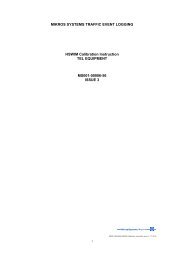
TDC Systems Limited <strong>HI</strong>-<strong>TRAC®</strong> <strong>EMU</strong> Overview<br />
The picture in Fig 1 shows two 65 Watt 12 volt panels. The mounting angle can clearly be<br />
seen, this installation is located in the North East of England. The mounting angle not only<br />
optimises the year round performance but also assists with self-cleaning.<br />
Fig 1<br />
The chart below shows the typical power output of a range of poly crystalline panels ranging<br />
from 10 Watts through to 80 Watts, all the panels are rated for 12 Volt operation. The current<br />
generated by the panels is listed in Amps this is the maximum current that the panel can<br />
produce. The peak voltage is the maximum voltage produced by the panels, this voltage is<br />
deliberately higher than the normal operating voltage in order to compensate for losses due<br />
to temperature, the higher the temperature the less efficient the panels become.<br />
The chart also shows the dimensions and weights of the various panels.<br />
Watts Volts Current<br />
Peak<br />
Voltage<br />
..47..<br />
Length Width Weight<br />
80 12 4.75A 16.8 146 50 9.5<br />
60 12 3.56A 16.8 111 50 7.2<br />
50 12 2.97A 16.8 94 50 6.3<br />
40 12 2.37A 16.8 77 50 5.4<br />
30 12 1.78A 16.8 60 50 3.9<br />
20 12 1.19A 16.8 42 50 3.0<br />
10 12 0.59A 16.8 42 27 1.5
TDC Systems Limited <strong>HI</strong>-<strong>TRAC®</strong> <strong>EMU</strong> Overview<br />
A power controller must monitor the output of the solar panel and regulate the voltage to a<br />
safe level for the system it is powering, it must also monitor the state of the battery and<br />
control the level of charging required, this is important because batteries are easily damaged<br />
by incorrect charging and electronic system can be damaged by incorrect supply voltage.<br />
Our range of sophisticated power control regulators controls the output from the solar panel<br />
ensuring that the voltage and current produced to power the electronic equipment is kept<br />
within the safe working range and that surplus power is used to charge and maintain the<br />
battery.<br />
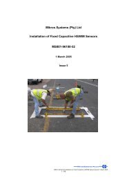
Fig 2<br />
The picture in Fig 2 shows two individual solar systems in operation. One of the polemounted<br />
10-Watt solar panels is providing the power for a remote data monitoring station<br />
located in the grey cabinet in the foreground. The system is backed up with a rechargeable<br />
lead acid battery, charged by the surplus energy produced by the solar panel.<br />
..48..