Application Note 01/2007 IonScan 800 â Ultra ... - Roth & Rau AG
Application Note 01/2007 IonScan 800 â Ultra ... - Roth & Rau AG
Application Note 01/2007 IonScan 800 â Ultra ... - Roth & Rau AG

You also want an ePaper? Increase the reach of your titles
YUMPU automatically turns print PDFs into web optimized ePapers that Google loves.
<strong>Roth</strong> & <strong>Rau</strong> <strong>AG</strong>, Gewerbering 3, 09337 Hohenstein-Ernstthal, Germany<br />
<strong>Application</strong> <strong>Note</strong> <strong>01</strong>/<strong>2007</strong><br />
<strong>IonScan</strong> <strong>800</strong> – <strong>Ultra</strong>-precise film thickness trimming for Semiconductor Technology<br />
Dr. Michael Zeuner, Matthias Nestler, Dr. Dietmar <strong>Roth</strong><br />
Summary<br />
Many applications in semiconductor technology are characterised<br />
by extreme requirements in terms of film thickness<br />
homogeneity. When manufacturing Bulk Acoustic Wave<br />
(BAW) components, it is necessary to adjust film thickness<br />
values of different materials with accuracy values in the nmrange.<br />
Standard processes, such as the film deposition technique,<br />
do not fulfil these homogeneity requirements. Thus it<br />
is necessary to perform local correction of the film thickness<br />
in a follow -up process. 1,2<br />
The authors here introduce a new method of local film<br />
thickness trimming and its technical implementation. During<br />
the process, the wafer is moved in front of a focussed ion<br />
beam. The local milling rate is controlled upon the residence<br />
time of the ion beam at certain positions. A modulated velocity<br />
profile is calculated specif ically for each wafer, in order to<br />
mill the material at the associated positions to the target film<br />
thickness.<br />
Depending on whether an inert or reactive ion beam process<br />
is used, it is possible to apply the <strong>IonScan</strong> technology for<br />
any material desired, such as Si 3N 4, SiO 2, Al 2O 3, AlN, W or<br />
NiFe.<br />
1. The principle of the ion beam trimming technology<br />
Over the past years, ion beam technologies have increasingly<br />
found their way into material processing in optics and<br />
semiconductor technology. The reason for this success is<br />
based on the characteristics of the ion beam processes outbalancing<br />
alternative technologies in terms of quality. In ion<br />
beam methods, the ion angle of incidence may be adjusted<br />
in a defined manner. Moreover, the process is characterised<br />
by a narrow ion energy distribution, controllability of the ion<br />
beam composition, as well as a high time and spatial constancy<br />
of the ion flow. Consequently, ion beam methods are<br />
mostly used for large area milling processes whose removal<br />
depth accuracies get close to the atomic scale. These procedures<br />
enable homogeneous removal or structuring with<br />
outstanding anisotropy characteristics across the whole substrate<br />
surface. 3-5<br />
Ion beam technologies not only allow a homogeneous<br />
substrate removal, but also locally resolved etching by controlling<br />
the local ion dose. Upon this dose, it is possible to<br />
correct heterogeneities of particular characteristics. When<br />
correcting film thickness or depth values of a structure, an<br />
error function gets etched down to the required function. The<br />
terms “ion beam trimming“ or “ion beam correction“ were introduced<br />
for this technique.<br />
Ion beam trimming can be performed with either an aperture-<br />
or a residence time method. In the aperture method, a<br />
large surface ion beam gets shaped with a shutter system in<br />
its temporal progression. The local ion dose is controlled in a<br />
defined way by variable aperture windows of different size,<br />
that are chronologically consecutive. However, the technical<br />
effort implementing the aperture method is notably high. At<br />
the same time, the process rates are low due to blanking a<br />
large share of the ion beam. Consequently, the aperture<br />
method is normally out of question for use in a production<br />
environment.<br />
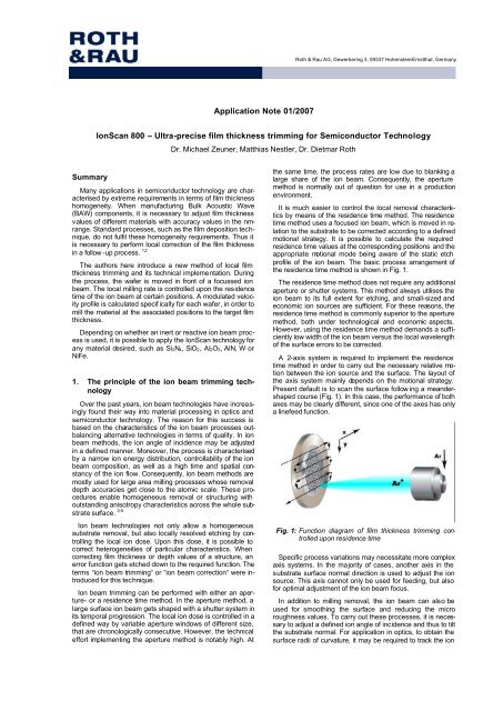
It is much easier to control the local removal characteristics<br />
by means of the residence time method. The residence<br />
time method uses a focused ion beam, which is moved in relation<br />
to the substrate to be corrected according to a defined<br />
motional strategy. It is possible to calculate the required<br />
residence time values at the corresponding positions and the<br />
appropriate motional mode being aware of the static etch<br />
profile of the ion beam. The basic process arrangement of<br />
the residence time method is shown in Fig. 1.<br />
The residence time method does not require any additional<br />
aperture or shutter systems. This method always utilises the<br />
ion beam to its full extent for etching, and small-sized and<br />
economic ion sources are sufficient. For these reasons, the<br />
residence time method is commonly superior to the aperture<br />
method, both under technological and economic aspects.<br />
However, using the residence time method demands a sufficiently<br />
low width of the ion beam versus the local wavelength<br />
of the surface errors to be corrected.<br />
A 2-axis system is required to implement the residence<br />
time method in order to carry out the necessary relative motion<br />
between the ion source and the surface. The layout of<br />
the axis system mainly depends on the motional strategy.<br />
Present default is to scan the surface follow ing a meandershaped<br />
course (Fig. 1). In this case, the performance of both<br />
axes may be clearly different, since one of the axes has only<br />
a linefeed function.<br />
Fig. 1: Function diagram of film thickness trimming controlled<br />
upon residence time<br />
Specific process variations may necessitate more complex<br />
axis systems. In the majority of cases, another axis in the<br />
substrate surface normal direction is used to adjust the ion<br />
source. This axis cannot only be used for feeding, but also<br />
for optimal adjustment of the ion beam focus.<br />
In addition to milling removal, the ion beam can also be<br />
used for smoothing the surface and reducing the micro<br />
roughness values. To carry out these processes, it is necessary<br />
to adjust a defined ion angle of incidence and thus to tilt<br />
the substrate normal. For application in optics, to obtain the<br />
surface radii of curvature, it may be required to track the ion
<strong>Roth</strong> & <strong>Rau</strong> <strong>AG</strong>, Gewerbering 3, 09337 Hohenstein-Ernstthal, Germany<br />
source along the surface normal and to control the etching<br />
distance. An axis system for such applications should have 2<br />
tilt and 3 linear axes.<br />
2. <strong>IonScan</strong> <strong>800</strong> system layout<br />
The <strong>IonScan</strong> <strong>800</strong> system is designed for wafer based film<br />
thickness trimming in semiconductor technology. With the<br />
handler and the process module, it is possible to create a<br />
cluster layout of the entire system, which is able to integrate<br />
both two load-locks and up to three process modules<br />
(Fig. 2).<br />
Process<br />
Chamber<br />
Ion Beam<br />
Chamber<br />
Fig. 2: General view of the <strong>IonScan</strong> <strong>800</strong><br />
Handler with<br />
Load-Lock<br />
The process chamber is fed with a 4 port handling robot<br />
(Fig. 2 right) by Brooks Automation Inc. or ASYS Automatisierungssysteme<br />
GmbH & Co. KG. The robot comprises a<br />
separately pumped load-lock, fitted with cassette lift and indexer,<br />
as well as a prealigner with combined OCR and barcode<br />
reader. A cluster system with a number of process<br />
chambers can be set up by any residual port allocation desired.<br />
The system components for ion beam trimming are housed<br />
in the process chamber (Fig. 2 left). The chamber size is<br />
about 0.80 m x 0.80 m x 0.50 m. Approximately 5 x 10 -5 Pa<br />
residual gas pressure is feasible with the turbomolecular<br />
pump set (2300 l/s). All door flanges are fitted with double V i-<br />
ton O-rings and are pumped differentially.<br />
Impedane<br />
Matching<br />
Discharge<br />
Arrangement<br />
Neutraliser<br />
Z Axis<br />
Fig. 3: Filament-free RF ion beam source cyberis 40-i<br />
(Shields to protect against redeposition removed.)<br />
An additional chamber at the front door houses the ion<br />
beam source to be accessed for maintenance activities upon<br />
a separate lid. A filament-free ion beam source cyberis 40-i<br />
made by <strong>Roth</strong> & <strong>Rau</strong> is used in the <strong>IonScan</strong> system<br />
(Fig. 3) 6 . The source is mounted completely in the vacuum<br />
with discharge chamber and impedance matching. The<br />
plasma excitation consists of a primary cylindrical coil supporting<br />
the discharge housing in the middle. According to the<br />
ICP principle, radio frequency power (13.65 MHz) is transferred<br />
inductively to the gas discharge. The full RF impedance<br />
matching is integrated in the rear part of the source<br />
housing. Thus, the source may be supplied with a 50 Ω coaxial<br />
cable of arbitrary length. In addition to the ion beam<br />
source, a hot filament or a RF neutraliser are used to neutralise<br />
the ion charge during processing of isolating substrates.<br />
Three different focussing multi-aperture grid systems made<br />
of graphite are available for the source. Each system consists<br />
of 3 individual grids of different geometry, which enable<br />
intentional control of both the ion flow and the focus<br />
characteristics. With the grid systems, it is possible to<br />
achieve a maximal total ion flow to 100 mA, as well as up to<br />
2 keV ion energy. Typically, the processes on the Ion-<br />
Scan <strong>800</strong> are run at a current ranging from 30 mA to 50 mA<br />
and an ion energy from 1.2 keV to 1.5 keV.<br />
It is possible to adequately fit the beam current profile of<br />
the ion beam by means of superposition of the Gaussian<br />
functions. The ion beam width is a relevant criterion for the<br />
film thickness correction quality (s. pt. 3). For typical film<br />
thickness errors, a beam profile standard deviation of<br />
5...10 mm is sufficient for a satisfying machining result. With<br />
the cyberis 40-i, it is also possible to achieve standard deviations<br />
down to 2 mm without reduction of the total beam current.<br />
The ion beam standard deviation is mostly influenced<br />
by the geometry of the grid system and the D.C. voltage applied.<br />
Ion current densities up to 20 mA/cm 2 are generated in<br />
the ion beam focus under typical operating conditions.<br />
In most of the processes, the ion beam source is run with<br />
inert gases (Ar, Xe). The discharge chamber of the source is<br />
completely made of aluminium oxide, so that fluorinecontaining<br />
process gases are used without any constraint,<br />
too.<br />
At the right of Fig. 4, the axis system with the wafer chuck<br />
are shown at opened chamber door. The axis system is dimensioned<br />
to machine wafers up to 200 mm. Wafer chucks<br />
are available in versions with 4“, 5“, 150 mm and 200 mm,<br />
both for w afers with flat and with notch.<br />
The wafer chuck is equipped with a clamping and transfer<br />
mechanism actuated by compressed air. The handler places<br />
the aligned wafer on 4 lift-off pins. The pins and the clamping<br />
ring are pneumatically operated and press the wafer against<br />
the body of the wafer chuck. A helium back side cooling is<br />
used for efficient heat transfer from the wafer to the water<br />
cooled chuck body. With this cooling principle, a power input<br />
of typically 100 W may be deduced efficiently out of the ion<br />
beam. As a rule, the resultant temperature at the wafer front<br />
side is below 120 o C, so that it is possible to process even<br />
wafers with photoresist without any problem.<br />
In addition to ion beam source and wafer chuck, the following<br />
components are functionally relevant:<br />
Rotational axis:<br />
The wafer chuck is mounted on a rotational axis. The rotational<br />
axis is first of all designed to tilt the wafer from the<br />
horizontal handling into the vertical processing pos ition. It is<br />
possible to continuously vary the tilting angle of the wafer<br />
holder from 0 to 100 deg. Generally the wafer is processed
<strong>Roth</strong> & <strong>Rau</strong> <strong>AG</strong>, Gewerbering 3, 09337 Hohenstein-Ernstthal, Germany<br />
Sputter<br />
Shields<br />
Y Axis<br />
ray, it is possible to run a complete current density profile of<br />
the ion beam within a few seconds. The array is used for<br />
routine check of the ion beam stability. Thus it is designed to<br />
determine the exact focus pos ition of the ion beam related to<br />
the wafer as well as the current density profile of the source<br />
can be mapped.<br />
Z Axis<br />
Ion Beam Source<br />
X Axis<br />
Rotational<br />
Axis<br />
Faraday<br />
Line<br />
8“ Wafer<br />
Chuck<br />
All <strong>IonScan</strong> <strong>800</strong> components and functions are controlled<br />
upon a PC system. The system environment is fitted with<br />
various modes for manual and automatic wafer processing,<br />
recipe administration, an MS SQL data base to log the system<br />
operation data, as well as an SECS/GEM interface for<br />
the process control system.<br />
Fig. 4: Interior view of the process chamber with ion beam<br />
source (left) and axis system with wafer chuck<br />
(right)<br />
at vertically incident ions, but one may also adjust any angle<br />
of incidence desired in order to increase the process rate.<br />
X-Y axis system:<br />
The x-y axis is designed to run the calculated residence<br />
time profile. The x-axis is equipped with a linear drive. Pr o-<br />
viding velocity values up to 500 mm/s and acceleration values<br />
of 20 m/s 2 , one may exactly run the residence time data.<br />
Due to the high velocity, base etching may be kept very low,<br />
at 0.5 … 1 nm only. Base etching defines the minimal removal<br />
carried out at each position of the wafer. The y-axis is<br />
designed for linefeed in the meander shaped motion, it is<br />
engineered as a spindle axis.<br />
Z axis:<br />
The z-axis is applied for positioning of the ion beam source<br />
related to the wafer. This way, the exact focus distance may<br />
be adjusted automatically. The z-axis is additionally necessary<br />
to process the wafer if the ion angle of incidence is different<br />
from 90°. Focus distance to the current line is automatically<br />
readjusted with each linefeed.<br />
Faraday array:<br />
The <strong>IonScan</strong> <strong>800</strong> system is equipped with a Faraday array<br />
consisting of 2 x 8 current probes. The probes and the w afer<br />
holder are mounted on the axis system. With the Faraday ar-<br />
3. Process flow and calculation of residence<br />
time<br />
To fulfil with the high homogeneity requirements in the<br />
<strong>IonScan</strong> applications, each wafer has to be processed in a<br />
specific way. Before ion beam trimming, it is required to<br />
measure the film thickness error of each wafer separately.<br />
This measurement is regularly carried out by an appropriate<br />
metrology (RF probes, Ellipsometry).<br />
As the first next step, it is necessary to calculate the res i-<br />
dence time for a known etch profile of the ion beam. The<br />
mathematical representation of the problem leads to a convolution<br />
between the res idence time t(x,y) to be found and<br />
the etch function R(x,y) of the ion beam, which has to be<br />
comply with the film thickness error z 0(x,y) (Fig. 5). The twodimensional<br />
etch function of the ion beam has to be found<br />
with static and dynamical test etching operations, which are<br />
carried out specifically for each material and for each parameter<br />
set of the ion beam source.<br />
∞<br />
( x,y) = ∫ ∫t( x ′,y<br />
′) R( x − x ′,y<br />
− y′<br />
)<br />
z 0<br />
−∞ −∞<br />
= t<br />
′<br />
∞<br />
( x,y) o R( x ′,y<br />
)<br />
dx′<br />
dy′<br />
/2.1/<br />
In the frequency domain, convolution operations can easily<br />
be executed as multiplications of the Fourier transformed<br />
functions.<br />
[ z ] FT[ t] ⋅FT[ R]<br />
FT 0<br />
= /2.2/<br />
20 nm 20 nm/s 40 ms<br />
Frequency / Film thickness<br />
error of BAW wafer<br />
Etch profile and focus of ion<br />
beam (Material dependent)<br />
Calculation of residence<br />
time data<br />
Wafer specific control data for<br />
axis system<br />
1 nm<br />
Process recipe data (Ion beam<br />
parameters, Cooling, Handling)<br />
Velocity modulated wafer<br />
scan<br />
Film thickness error after ion<br />
beam processing<br />
Fig. 5: Flowchart representation of wafer processing on the <strong>IonScan</strong> <strong>800</strong>
<strong>Roth</strong> & <strong>Rau</strong> <strong>AG</strong>, Gewerbering 3, 09337 Hohenstein-Ernstthal, Germany<br />
As a result, the inverse problem turns out to be in the frequency<br />
domain as follows<br />
−1<br />
[ FT[ z0<br />
] FT[ ] ]<br />
− t = FT 1 R<br />
/2.3/<br />
Inverse problems are generally known as sophisticated<br />
subjects in mathematical and numerical techniques, and are<br />
mostly used for applications in image processing. 7 Real<br />
problems according to /2.4/, as a rule, can not be solved exactly,<br />
they can only be solved as approximations. Approx i-<br />
mate solutions for t(x’,y’) may be found by iterative methods<br />
when predefining special objectives or target criteria. In any<br />
case it is necessary to do additional arrangements in order to<br />
make these methods numerically stabile.<br />
When executing the iteration in the frequency domain,<br />
transformation back into the space domain is carried our after<br />
each iteration step i, and residual error f of the calculation<br />
is determined:<br />
[ ] [ ]<br />
( i) ( i<br />
f = z −FT<br />
t ) FT R<br />
/2.4/<br />
0<br />
Based on the error function, the new residence time matrix<br />
t (i+1) is calculated with an damping factor α. The iteration is<br />
aborted either after achieving a predefined c ycle number or if<br />
dropping below a residual error of the iteration.<br />
[ [ ] [ ] ]<br />
( i+<br />
1) ( i) −1<br />
( i)<br />
−1<br />
t = t + αFT<br />
FT f FT R<br />
/2.5/<br />
The residence time matrix provides the wafer specific data<br />
for the axis system control. Finally, they are transformed into<br />
local velocity and acceleration data.<br />
Into process control, there are not only incorporated the<br />
wafer specific residence time data, but also recipe data specific<br />
to each material to be trimmed. These recipe data include<br />
the two-dimensional removal function of the ion beam,<br />
the settings of ion beam source and neutraliser, wafer geometry,<br />
as well as data for helium cooling (Fig. 5).<br />
The wafer is machined with these input data, without additional<br />
feedback of the process.<br />
In the <strong>IonScan</strong> <strong>800</strong> system, a special software IonTrim is<br />
available for residence time calculation according to the<br />
above described method. IonTrim was particularly engineered<br />
for this technique. Fig. 6 illustrates the user interface<br />
enabling access to various functionalities:<br />
Interpolation:<br />
Information about the film thickness error may be provided<br />
in any local distribution. Both layer thickness error and removal<br />
function of the ion beam have to be inter- and extrapolated<br />
to unified calculation matrices. Multiple choice methods<br />
are available for inter- and extrapolation. The program is additionally<br />
capable of considering a correction function for local<br />
deviations in the removal rate.<br />
Filtering:<br />
If necessary, it is possible to use different filters for the film<br />
thickness error function whose filter parameters may be configured.<br />
Residence time calculation:<br />
In this menu, the residence time is calculated according to<br />
/2.5/. However, not all residence time data calculated may be<br />
travelled by the real axis system. IonTrim checks all calculated<br />
time values and adapts them to the value range actually<br />
feas ible.<br />
Turning after completing each meander line, together with<br />
the residual beam ratio remaining on the w afer, may act on<br />
the machining result. For this reason, in calculation, the residence<br />
time matrix exceeds the wafer radius by a definable<br />
radius.<br />
Error analysis:<br />
With error analysis, one can estimate consequences of inaccuracies<br />
in mechanical adjustment or deviations in the removal<br />
function.<br />
Calculation of axis data:<br />
Finally, IonTrim calculates the entire control records for the<br />
axis system and transforms the binary data to the control.<br />
For modelling and optimisation of layer thickness trimming,<br />
IonTrim cannot be only installed at the <strong>IonScan</strong> <strong>800</strong> system,<br />
but also any other PC.<br />
4. Use in frequency trimming of Bulk<br />
Acoustic Wave (BAW) components<br />
High-frequency components for the mobile radio technology<br />
increasingly use Bulk Acoustic Wave (BAW) rather than<br />
the Surface Acoustic Wave (SAW) components, which have<br />
been established up to now. The reasons for this change result<br />
from several advantages like enhanced product characteristics,<br />
smaller device size, less sensitivity against influences<br />
from the outside, such as temperature or electrostatic<br />
discharge, as well as the lower production costs based on as<br />
wide as possible standard CMOS technologies, thus avoiding<br />
special materials for substrates.<br />
The main item of each BAW component (Fig. 7) is a piezoelectric<br />
film regularly made of aluminium nitride and contacted<br />
by two electrodes. To generate an acoustic resonator,<br />
the thickness of the piezoelectric film has to be λ/2 of the<br />
wavelength of the transversal acoustic wave.<br />
The resonator has to be sufficiently acoustically isolated<br />
from the substrate material. In the past, so called Free Bulk<br />
Upper Electrode<br />
Bottom Electrode<br />
Piezo<br />
Tuning<br />
Passivation<br />
λ/4 Films of high and<br />
low acoustic Impedance<br />
Substrate<br />
Fig. 6: User interface of the IonTrim software for res idence<br />
time calculation<br />
Fig. 7: Principle structure of a Bulk Acoustic Wave (BAW)<br />
resonator
<strong>Roth</strong> & <strong>Rau</strong> <strong>AG</strong>, Gewerbering 3, 09337 Hohenstein-Ernstthal, Germany<br />
BEFORE<br />
AFTER<br />
Error Range:<br />
Mean Error:<br />
Standard Deviation:<br />
20 ... 110 nm<br />
69.1 nm<br />
16.6 nm<br />
Error Range:<br />
Mean Error:<br />
Standard Deviation:<br />
-1 ... 3 nm<br />
0.46 nm<br />
0.59 nm<br />
Fig. 8: Film thickness error of an Si 3N 4 layer before (left) and after ion beam trimming (right)<br />
(position coordinates left/bottom [mm], film thickness error right [nm])<br />
Acoustic Resonator (FBAR) arrangements were used. In this<br />
construction, isolation is obtained by building an air cavity.<br />
The resonator is built up unsupported over this cavity. In the<br />
meantime, the Solid Mounted Resonator (SMR) principle has<br />
become accepted (s. Fig. 7). In this structure, acoustic isolation<br />
is achieved with an acoustic Bragg mirror made of alternating<br />
λ/4 layers with high and low acoustic impedance. Depending<br />
on the impedance differences, such as between<br />
tungsten and silicon oxide, it may be possible to achieve an<br />
excellent acoustic isolation even with only a few films.<br />
The frequency is finally tuned with a low additional mass,<br />
which is deposited onto the upper electrode as another film,<br />
mostly silicon nitride.<br />
The operation that makes the production of BAW resonators<br />
mainly demanding, is exact adjustment of the required<br />
film thickness values, in order to keep the low frequency tolerance<br />
range of about 0.1 %. It is also necessary to guarantee<br />
an adequate accuracy of the film thickness values across<br />
the whole wafer, which can not be obtained in these narrow<br />
tolerances with standard semiconductor technology equipment.<br />
The <strong>IonScan</strong> <strong>800</strong> is a system suitable to manufacture<br />
these components. The <strong>IonScan</strong> <strong>800</strong> is capable of adequately<br />
trimming of all films in a BAW stack. In addition to<br />
Counts<br />
100<br />
10<br />
1<br />
After Trimming<br />
Before Trimming<br />
the film thickness trimming of the mass load, <strong>IonScan</strong> can<br />
also be applied for trimming of the piezo-resonator and the<br />
acoustic mirror. With this step like trimming strategy not only<br />
the final variation of the device frequency is better met but<br />
also other device parameters like the Q-Factor gets clearly<br />
improved.<br />
Fig. 8 elucidates the thickness distribution of a Si 3N 4 film,<br />
measured by ellipsometry, before and after ion beam trimming.<br />
With the <strong>IonScan</strong> <strong>800</strong> system, it is possible to correct<br />
film thickness errors arbitrarily distributed across the wafer.<br />
The local resolution of the technique is significantly determined<br />
by the standard deviation of the ion beam profile. In<br />
the example demonstrated, the ion beam was run with argon.<br />
For Si 3N 4, in the focus of the ion beam a removal rate of<br />
20.0 nm/s and a volume rate of 6.1 x 10 -3 mm 3 /s are<br />
achieved. Under these working conditions, base etching at<br />
all wafer positions is only 1.7 nm.<br />
Typical rates for materials to be processed range from approximately<br />
10 to 30 nm/s for argon processing. With reactive<br />
gases, one may rise the rates to the three- or fourfold,<br />
depending on each material. Due to the reserves in the axis<br />
parameters, the <strong>IonScan</strong> <strong>800</strong> system is capable of handling<br />
such high milling rates without any problem.<br />
In the example demonstrated in Fig. 8, the average error is<br />
diminished by about a factor of 150, and the standard deviation<br />
of the film thickness error by about 30. After machining,<br />
there remains only a 0.46 nm deviation from the nominal film<br />
thickness at a standard deviation of 0.57 nm across the<br />
whole wafer. Fig. 9 represents the film thickness distribution<br />
before (red) and after trimming (blue). The process time to<br />
machine the wafer was less than 5 min.<br />
A slight processing error appeared towards the wafer<br />
edge. These marginal effects result from the calculation and<br />
the extrapolation procedures used, on the one hand, and<br />
from a slightly changed neutralisation at the wafer margin, on<br />
the other hand. These deviations may be compensated in<br />
the software when defining a locally variable milling rate.<br />
0 20 40 60 80 100<br />
Thickness Error [nm]<br />
Fig. 9: Film thickness distribution before and after ion<br />
beam trimming<br />
References<br />
1<br />
K.M. Lakin, G.R. Kline, K.T. McCarron, High-Q: IEEE<br />
Trans. Microw. Theory Tech. , 12, (1993), 41
<strong>Roth</strong> & <strong>Rau</strong> <strong>AG</strong>, Gewerbering 3, 09337 Hohenstein-Ernstthal, Germany<br />
2<br />
R. Aigner: 2nd Int. Symp. Acoustic Wave Dev. Fut. Mob.<br />
Comm. Syst., Chiba (Japan) 2004<br />
J.J. Cuomo, S.M. Rossnagel and H.R. Kaufman: Handbook<br />
of ion beam processing technology, Noyes Publ.,<br />
Park Ridge (1989)<br />
B. Wolf: Ion sources, CRC Press, Boca Raton (1995)<br />
M. Zeuner, F. Scholze, H. Neumann, T. Chassé, G. Otto,<br />
D. <strong>Roth</strong>, A. Hellmich, B. Ocker: Surf. Coat. Technol. 142-<br />
144 (20<strong>01</strong>), 11<br />
M. Zeuner, F. Scholze, B. Dathe, H. Neumann: Surf. Coat.<br />
Technol. 142-144 (20<strong>01</strong>), 39<br />
7 R. Klette, P. Zamperoni: Handbuch der Operatoren für<br />
die Bildverarbeitung, Bildtransformationen für die digitale<br />
Bildverarbeitung, Vieweg, Braunschweig (1992)<br />
3<br />
4<br />
5<br />
6<br />
Contact data<br />
<strong>Roth</strong> & <strong>Rau</strong> <strong>AG</strong><br />
Dr. Michael Zeuner<br />
Gewerbering 3<br />
09337 Hohenstein-Ernstthal<br />
Germany<br />
Phone: +49 (0) 3723 4988 33<br />
Fax: +49 (0) 3723 4988 25<br />
e-mail: michael.zeuner@roth-rau.de
<strong>Roth</strong> & <strong>Rau</strong> <strong>AG</strong>, Gewerbering 3, 09337 Hohenstein-Ernstthal, Germany