AD8307 Low Cost DCâ500 MHz, 92 dB Logarithmic Amplifier Data ...
AD8307 Low Cost DCâ500 MHz, 92 dB Logarithmic Amplifier Data ...
AD8307 Low Cost DCâ500 MHz, 92 dB Logarithmic Amplifier Data ...

Create successful ePaper yourself
Turn your PDF publications into a flip-book with our unique Google optimized e-Paper software.
<strong>AD8307</strong><br />
USING THE <strong>AD8307</strong><br />
The <strong>AD8307</strong> has very high gain and a bandwidth from dc to<br />
over 1 GHz, at which frequency the gain of the main path is still<br />
over 60 <strong>dB</strong>. Consequently, it is susceptible to all signals within<br />
this very broad frequency range that find their way to the input<br />
terminals. It is important to remember that these are quite indistinguishable<br />
from the wanted signal, and will have the effect of<br />
raising the apparent noise floor (that is, lowering the useful<br />
dynamic range). For example, while the signal of interest may<br />
be an IF of 50 <strong>MHz</strong>, any of the following could easily be larger<br />
than the IF signal at the lower extremities of its dynamic range:<br />
60 Hz hum, picked up due to poor grounding techniques; spurious<br />
coupling from a digital clock source on the same PC board; local<br />
radio stations; and so on.<br />
Careful shielding is essential. A ground plane should be used to<br />
provide a low impedance connection to the common pin COM,<br />
for the decoupling capacitor(s) used at VPS, and as the output<br />
ground. It is inadvisable to assume that the ground plane is an<br />
equipotential. Neither of the inputs should be ac-coupled<br />
directly to the ground plane, but should be kept separate from<br />
it, being returned instead to the low associated with the source.<br />
This may mean isolating the low side of an input connector with<br />
a small resistance to the ground plane.<br />
Basic Connections<br />
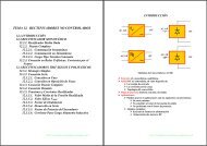
Figure 12 shows the simple connections suitable for many applications.<br />
The inputs are ac-coupled by C1 and C2, which should<br />
have the same value, say, C C . The coupling time constant is<br />
R IN C C /2, thus forming a high-pass corner with a 3 <strong>dB</strong> attenuation<br />
at f HP = 1/(pR IN C C ). In high frequency applications, f HP should<br />
be as large as possible in order to minimize the coupling of<br />
unwanted low frequency signals. Conversely, in low frequency<br />
applications, a simple RC network forming a low-pass filter<br />
should be added at the input for the same reason. For the case<br />
where the generator is not terminated, the signal range should<br />
be expressed in terms of the voltage response, and extends from<br />
–85 <strong>dB</strong>V to +6 <strong>dB</strong>V.<br />
INPUT<br />
–75<strong>dB</strong>m TO<br />
+16<strong>dB</strong>m<br />
4.7<br />
C1 = C C<br />
NC<br />
R<br />
INP VPS ENB INT<br />
IN <br />
R T <strong>AD8307</strong><br />
1.1k<br />
INM COM OFS OUT<br />
C2 = C C<br />
0.1F<br />
NC<br />
NC = NO CONNECT<br />
V P , 2.7V–5.5V<br />
AT 8mA<br />
OUTPUT<br />
25mV/<strong>dB</strong><br />
Figure 12. Basic Connections<br />
Where it is necessary to terminate the source at a low impedance,<br />
the resistor R T should be added, with allowance for the<br />
shunting effect of the basic 1.1 kΩ input resistance (R IN ) of the<br />
<strong>AD8307</strong>. For example, to terminate a 50 Ω source, a 52.3 Ω 1%<br />
tolerance resistor should be used. This may be placed on the<br />
input side or the log-amp side of the coupling capacitors; in<br />
the former case, smaller capacitors can be used for a given<br />
frequency range; in the latter case, the effective R IN is lowered<br />
directly at the log-amp inputs.<br />
Figure 13 shows the output versus the input level, in <strong>dB</strong>m, when<br />
driven from a terminated 50 Ω generator, for sine inputs at<br />
10 <strong>MHz</strong>, 100 <strong>MHz</strong>, and 500 <strong>MHz</strong>; Figure 14 shows the typical<br />
logarithmic conformance under the same conditions. Note that<br />
+10 <strong>dB</strong>m corresponds to a sine amplitude of 1 V, equivalent to<br />
an rms power of 10 mW in a 50 Ω termination. But if the termination<br />
resistor is omitted, the input power is negligible. The use<br />
of <strong>dB</strong>m to define input level therefore needs to be considered<br />
carefully in connection with the <strong>AD8307</strong>.<br />
OUTPUT VOLTAGE (V)<br />
3.0<br />
2.5<br />
2.0<br />
1.5<br />
1.0<br />
0.5<br />
500<strong>MHz</strong><br />
10<strong>MHz</strong><br />
100<strong>MHz</strong><br />
0<br />
–80 –70 –60 –50 –40 –30 –20 –10 0 10 20<br />
INPUT LEVEL (<strong>dB</strong>m)<br />
Figure 13. Log Response at 10 <strong>MHz</strong>, 100 <strong>MHz</strong>, and 500 <strong>MHz</strong><br />
ERROR (<strong>dB</strong>)<br />
5<br />
4<br />
3<br />
2<br />
1<br />
0<br />
–1<br />
–2<br />
–3<br />
–4<br />
10<strong>MHz</strong><br />
500<strong>MHz</strong><br />
100<strong>MHz</strong><br />
–5<br />
–80 –70 –60 –50 –40 –30 –20 –10 0 10 20<br />
INPUT LEVEL (<strong>dB</strong>m)<br />
Figure 14. <strong>Logarithmic</strong> Law Conformance at 10 <strong>MHz</strong>,<br />
100 <strong>MHz</strong>, and 500 <strong>MHz</strong><br />
Input Matching<br />
Where higher sensitivity is required, an input matching network<br />
is valuable. Using a transformer to achieve the impedance transformation<br />
also eliminates the need for coupling capacitors,<br />
lowers the offset voltage generated directly at the input, and<br />
balances the drives to INP and INM. The choice of turns ratio<br />
will depend somewhat on the frequency. At frequencies below<br />
50 <strong>MHz</strong>, the reactance of the input capacitance is much higher<br />
than the real part of the input impedance. In this frequency range,<br />
a turns ratio of about 1:4.8 will lower the input impedance to<br />
50 Ω while raising the input voltage, thus lowering the effect of<br />
the short circuit noise voltage by the same factor. There will be<br />
a small contribution from the input noise current, so the total<br />
noise will be reduced by a somewhat smaller factor. The intercept<br />
will also be lowered by the turns ratio; for a 50 Ω match, it will<br />
be reduced by 20 log 10 (4.8) or 13.6 <strong>dB</strong>.<br />
REV. B<br />
–13–